

MODEL 408
"
"
"
"
"
"
"
TIME MARK is a division of
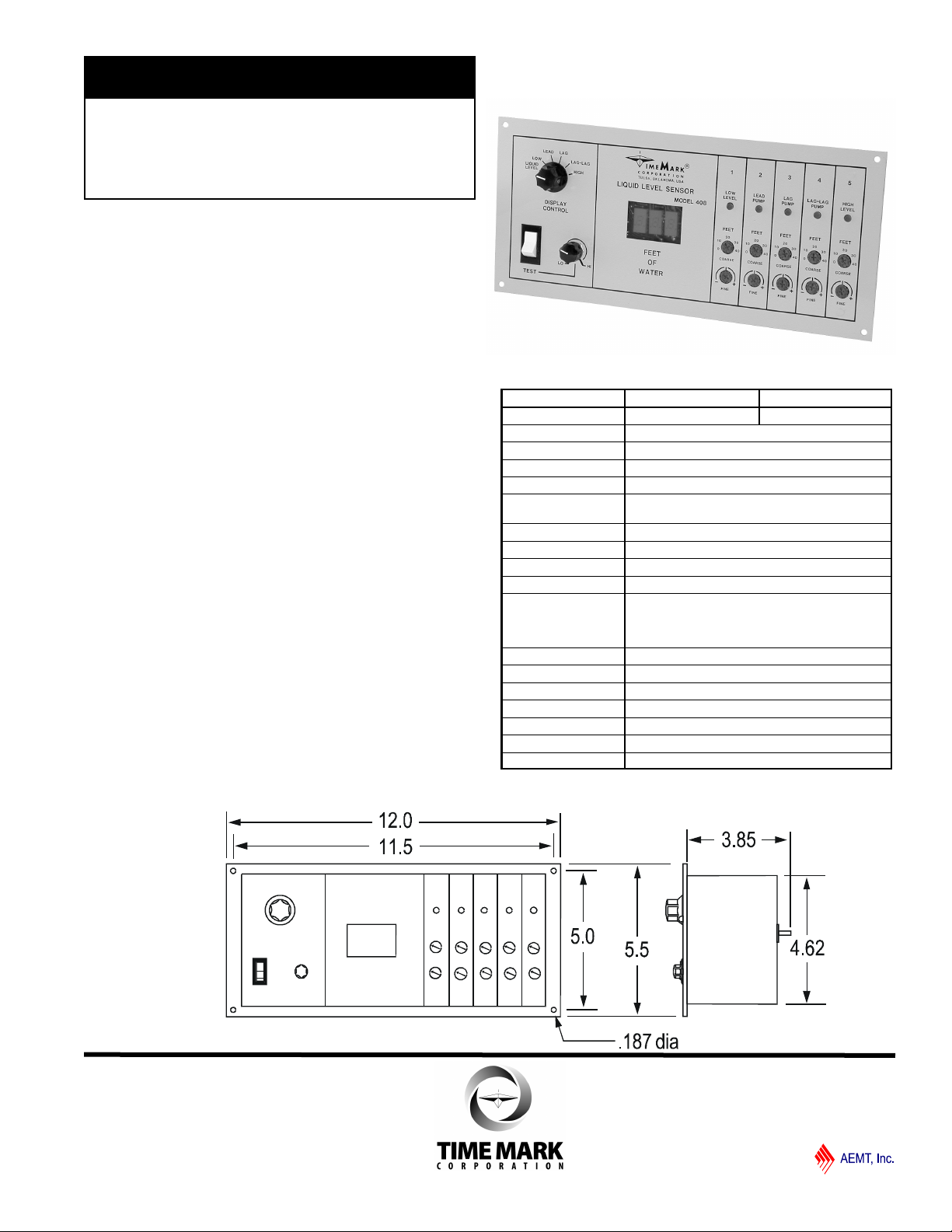
Liquid Level
Sensor
Digital display of water depth
Solid-state outputs
Five adjustable trip points
4-20 mA output
Moisture protected circuits
DESCRIPTION
The Model 408 Liquid Level Sensor operates in conjunction
with a Model 407 Controller for bubbler-type triplex pumping
systems. The 408 contains an air pressure-to-voltage transducer
and requires only a small compressor capable of 15 psi (pounds
per square inch) to operate the system down to approximately
35 feet.
The Model 408’s five outputs are designed to replace the float
switch inputs to a Model 407, or to be used with a Model 448
Output Relay Board. A 4-20 mA signal output provides for other
control applications.
A 3-digit LED display continuously shows the liquid level to a
tenth of a foot when the Display Control switch is in the Liquid
Level position. Other settings of the switch allow setting of the
liquid level trip points. LED Indicators illuminate as the levels are
exceeded. A test control allows the trip settings to be checked
without actually raising or lowering the liquid level.
DIMENSIONS
SPECIFICATIONS
MODEL 408-24V 408-115V
Input voltage 20-28 VAC 105-130 VAC
Input frequency 47-65 Hz
Power consumption 2 Watts
Air pressure input 0-15 psi max.
Input air supply fitting Requires 3/16” I.D. tubing
Maximum liquid level
displayed
Calibration accuracy ± 2%
Repeat accuracy ± 1% in fixed condition
Repeat accuracy ± 2% at 32º -140º F
Dead band 0.1 foot
Switching outputs 5 open-collector transistors rated for regulated
12VDC, 10 mA, maximum. Designed as inputs
for the Model 407 Liquid Level Controller or
Model 448 Output Relay Board
Signal outputs 4-20 mA output proportional to 0-40 feet of water
Operating temperature - 20º to +122º F
Storage temperature - 4º to +158º F
Humidity tolerance 0-97% without condensation
Case material 20 gauge Steel
Termination Removable terminal strip
Weight 3.5 lbs
34.6 feet
01/2012 page 1 of 4
© 2012 TIME MARK CORPORATION
MODEL 408
TIME MARK is a division of
Liquid Level Sensor
READ ALL INSTRUCTIONS BEFORE INSTALLING, OPERATING OR SERVICING THIS DEVICE.
KEEP THIS DATA SHEET FOR FUTURE REFERENCE.
POTENTIALLY HAZARDOUS VOLTAGES ARE PRESENT AT THE TERMINALS OF THE MODEL 408.
ALL ELECTRICAL POWER SHOULD BE REMOVED WHEN CONNECTING OR DISCONNECTING WIRING.
DO NOT EXCEED THE OUTPUT OR INPUT RATINGS, AS STATED IN THE SPECIFICATIONS.
PROTECT THE UNIT WITH PROPERLY RATED FUSES.
DO NOT INSTALL IN DAMP OR MOIST AREAS.
THIS DEVICE SHOULD BE INSTALLED AND SERVICED BY QUALIFIED PERSONNEL.
GENERAL SAFETY
Installation Instructions
INSTALLATION
Mount the Sensor in a suitable enclosure. If a Model 448
relay module is being used, mount it in a suitable location near the Sensor.
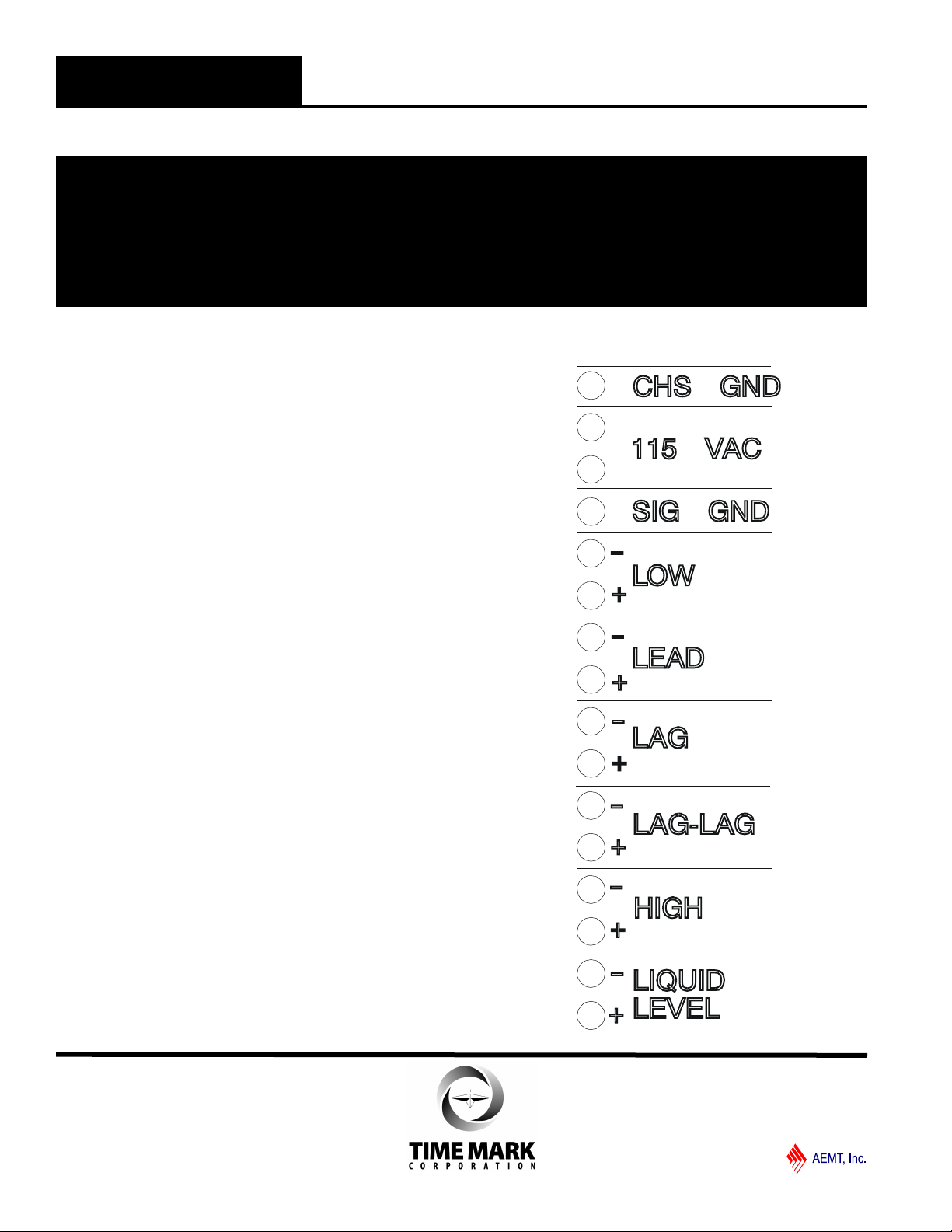
Referring to the terminal block decal on the sensor and
the illustration on this page, make the following connections
1. Connect a chassis ground to the terminals marked
CHS GND.
2. Connect operating power (24 or 120 VAC) to the
terminals marked for input voltage.
3. Observing polarity, connect the LOW terminals to the
LOW terminals on the 407. For connections to 448,
refer to connection chart on page 4.
4. Repeat step 3 for the LEAD, LAG, LAG-LAG, and
HIGH terminals.
5. The terminals marked LIQUID LEVEL are the 4-20
mA output. If used, connect these terminals to the
appropriate control circuitry. Observe polarity.
Connect a 3/16” I.D. tubing to the air supply fitting on the
back of the 408. Connect the other end of the tubing to
the air compressor and the tank or well .Apply operating
power and proceed to the adjustment procedure.
01/2012 page 2 of 4
© 2012 TIME MARK CORPORATION

MODEL 408
TIME MARK is a division of
Liquid Level Sensor
Model 408 Panel
PANEL LAYOUT
A. Display control switch used to select liquid level or
level setting.
B. 3-Digit LED indicator reads depth in feet.
C. Test switch enables simulated level change by
rotating control D.
D. Simulates liquid level change when switch C is
pressed.
E. Indicator LED shows when level is reached (one
per level)
F. Coarse adjustment for setting level trip point (one
per level)
G. Fine adjustment for setting level trip point (one per
level)
ADJUSTMENT
1. The trip points are set using coarse and fine
adjustment pots; the results are shown on the LED
display. To adjust the device, set the display control
knob (A) to LOW and adjust the low level coarse
adjustment (F) to the approximate desired level. A fine
adjustment (G) is located below the coarse adjustment.
The trip level will be shown on the LED display (B).
2. Repeat step 1 for the lead, lag, lag-lag, and high
level adjustments.
3. Set the display control knob to the LIQUID LEVEL
position. The Sensor is now ready to operate.
TESTING
For testing purposes a test switch (C) and LO_HI
adjustment (D) are provided. Set the adjustment to LO,
then press and hold the test switch. As the adjustment
is turned clockwise (HI), the LED display will show an
increasing simulated liquid depth. As each level is
reached the appropriate LED indicator (E) will illuminate
and the output should activate (pump will turn on,
output relay will energize, or alarm will sound).
TROUBLESHOOTING
Problem: Erratic and/or unstable operation when
used with 407.
Cause: Signal ground wire between the two units is
not connected.
Solution: Connect signal ground.
Problem: In test position, display reads other than
zero with adjustment fully counterclockwise
Cause: This is a normal condition; fully
counterclockwise on the adjustment may be
below zero.
Solution: Turn the adjustment slightly clockwise; the
display should read zero (or higher).
Note: This device is not a field repairable unit. Should the unit not
operate properly during installation or testing, insure that all electrical,
ground, and physical connections are correct. Verify that the proper
voltage is applied and check all fuses. Contact the factory if
everything is correct and the device still fails to operate. Should the
sensor fail during use, contact the factory for instructions on returning
the device for repair.
WARRANTY
The Model 408 Liquid Level Sensor is warranted to be free
from defects in materials and workmanship for one year.
Should this device fail to operate, we will repair or replace it for
one year from the date of purchase. Contact the Time Mark
Sales department, Monday through Friday; 8 a.m. to 5 p.m.,
CST, for further details.
01/2012 page 3 of 4
© 2012 TIME MARK CORPORATION

MODEL 408
TIME MARK is a division of
Liquid Level Sensor
TYPICAL APPLICATIONS
Note:
1. Remote alarm contacts
are normally closed
contacts located at the
motor controllers.
Jumper closed if not
used.
2. Power fail contacts close
on power failure.
3. Alarm Bell and Alarm
Light contacts close on
alarm condition.
Model 408 to Model 407
Model 408 to Model 448
01/2012 page 4 of 4
© 2012 TIME MARK CORPORATION
 Loading...