

TIME MARK is a division of
MODEL 4052
Pump-Down
Controller
4-20mA Input/Scalable Output
Seal Fail Monitoring
Duplex Pump Alternation
Hand-Off-Auto Controls
Dual Run-time Meters
RS-485/Modbus Communications
DESCRIPTION
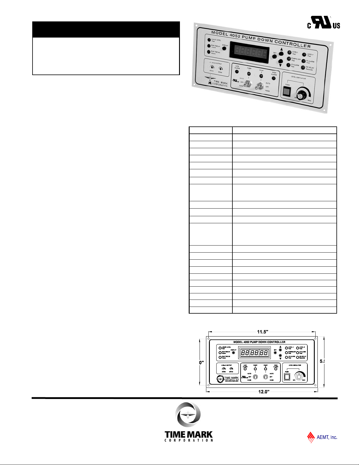
The Model 4052 Pump-Down Controller provides total
control for duplex pumping systems. The Model 4052
monitors, controls and displays the liquid level in a tank
or reservoir. Maximum selectable depth is from 11.5 ft.
to 346 ft.
The input to the Model 4052 can be from any 2 or 3-wire
transducer with a 4-20mA output representing the
selected depth. A 24VDC regulated probe supply is
included. A Level Simulator is provided to aid in
programming these five set points; Low Alarm, Pumps
Off, Level 1, Level 2 and High Alarm.
A universal zero to 30 second On Delay can be
programmed to prevent outputs from closing due to
input fluctuations caused by turbulent conditions. An
additional 4-20mA output with zero and span controls is
provided for a chart recorder or other external device.
Four heavy-duty 10 amp, 120V contacts are provided
for pump control and alarm activation. An auto-dialer or
other emergency device can be activated with the SPDT
power loss relay. This relay is held open when power is
applied.
Pump outputs include duplex alternation as well as
hand-off-auto switches. Pump run-time can be
displayed for each pump with tenth of an hour
resolution, up to 99,999.9 hours. The Model 4052 can
be panel-mounted (11 1/8” x 4 5/8) or surface-mounted
using the optional surface-mounting kit (Model 4000).
SPECIFICATIONS
MODEL 4052
Input Voltage 120VAC ± 10% 50/60Hz
Pwr Consumption 8W max.
Signal Input 4-20mA (optional 0-5V), 2 or 3 wire
Signal Input Load 250 ohms max.
Dead Band 1% of full scale
Repeat Accuracy ± 1% of scaled max. (fixed conditions)
Display Type 6 digit red LED display
Display Ranges Level: 00.0 to 346 ft
Runtime: zero to 99,999.9 hours
Delay: zero to 30 seconds
Display Resolution 1 decimal place
Control Contacts 4 SPDT 10A at 120VAC resistive
Power Loss Relay 1 SPDT 5A at 120VAC resistive
Signal Output Output is factory set to track the 4-20mA input.
Zero and span adjustments are provided: as
little as a 2mA change can cause a full swing of
the output.
Signal Output Load 300 ohms max.
Probe Supply 24VDC regulated
Setpoints 3 levels, 2 alarms, all user-adjustable
Operating Temp +14º to +122º F
Humidity Tolerance 0-97% w/o condensation
Enclosure Material 16 gauge steel
Termination removable terminal strips
Dimensions H: 5.5” W: 12.0” D: 4.75”
Weight 6.0 pounds
Agency Approvals UL Recognized (U.S. & Canadian)
DIMENSIONS
11440 Ea s t Pi n e St r e e t
Tu l s a , O k l a h o m a 74 1 1 6
Page 1 of 8 01/2017
© 2017 TIME MARK CORPORATION
TIME MARK is a division of
MODEL 4052
Pump Down Controller
READ ALL INSTRUCTIONS BEFORE INSTALLING, OPERATING OR SERVICING THIS DEVICE.
KEEP THIS DATA SHEET FOR FUTURE REFERENCE.
POTENTIALLY HAZARDOUS VOLTAGES ARE PRESENT AT THE TERMINALS OF THE MODEL 4052.
ALL ELECTRICAL POWER SHOULD BE REMOVED WHEN CONNECTING OR DISCONNECTING WIRING.
DO NOT EXCEED THE OUTPUT OR INPUT RATINGS, AS STATED IN THE SPECIFICATIONS.
PROTECT THE UNIT WITH PROPERLY RATED FUSES.
DO NOT INSTALL IN DAMP OR MOIST AREAS.
THIS DEVICE SHOULD BE INSTALLED AND SERVICED BY QUALIFIED PERSONNEL.
GENERAL SAFETY
Installation Instructions
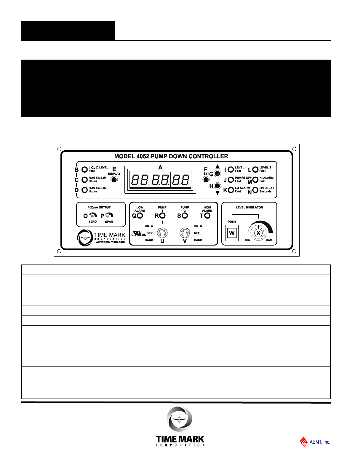
figure 1. Front Panel Controls
6 digit LED display
A
Indicates display is showing LIQUID LEVEL
B
Indicates display is showing PUMP #1 runtime
C
Indicates display is showing PUMP #2 runtime
D
Switches display between B, C and D
E
Push to enter SET mode
F
Push to INCREASE setting
G
Push to DECREASE setting
H
Indicates display is showing LEVEL 1 setting
I
Indicates display is showing PUMPS OFF setting
J
Indicates display is showing LOW ALARM setting
K
Indicates display is showing LEVEL 2 setting
L
Indicates display is showing HIGH ALARM setting
M
Indicates display is showing ON DELAY setting
N
Controls ZERO setting for 4 to 20mA output
O
Controls SPAN setting for 4 to 20mA output
P
Indicates LOW ALARM ACTIVE (low alarm relay-closed)
Q
Indicates PUMP #1 RUNNING (pump #1 relay-closed)
R
Indicates PUMP #2 RUNNING (pump #2 relay-closed)
S
Indicates HIGH ALARM ACTIVE (high alarm relay-closed)
T
3-position switch HAND-OFF-AUTO Pump #1
U
3-position switch HAND-OFF-AUTO Pump #2
V
Momentary pushbutton
W
engages LEVEL SIMULATOR
Controls SIMULATED LEVEL
X
(when SIMULATOR button is engaged)
11440 Ea s t Pi n e St r e e t
Tu l s a , O k l a h o m a 74 1 1 6
Page 2 of 8 01/2017
© 2017 TIME MARK CORPORATION
MODEL 450
3-WIRE
TRANSDUCER
+24VDC
4-20mA
PIN 5
PIN 8
4-20mA
IN
+ -
GND
PIN 4
4-20mA
OUT
+ -
+24VDC
OUT
+ -
GND
GND
4-20mA
IN
+ -
4-20mA
OUT
+ -
+24VDC
OUT
+ -
- EXCITATION (BLK)
+ EXCITATION (RED)
MODEL 456-15
PRESSURE
TRANSDUCER
TIME MARK is a division of
MODEL 4052
Pump Down Controller
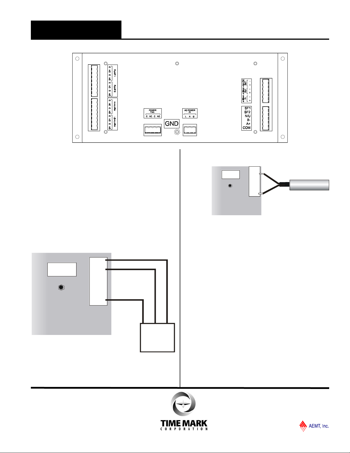
figure 2. Back Panel Controls
MOUNTING & WIRING
Mount the Model 4052 Pump-Down Controller in a
panel or suitable enclosure (see Time Mark’s Model
4000 Surface Mount kit).
Referring to the terminal block decals on the unit, and
Figure 2, make the following connections:
SIGNAL INPUT
With a 3-wire 4-20mA transducer (see Time Mark
Model 450) remotely mounted, connect the +24VDC
OUT terminal to the voltage input of the transducer
(figure 3). Connect the 4-20mA IN terminals to the loop
terminals of the transducer. OBSERVE POLARITY.
figure 3.
Connect a 2-wire transducer (pressure, ultrasonic, etc.)
as shown in figure 4.
figure 4.
SIGNAL OUTPUT
The 4-20mA output is proportional to the input signal.
This allows for very accurate remote monitoring of level
changes. The factory default is for the output to track
the input; that is, a 4mA signal represents 00.0 feet, and
a 20mA signal represents 34.6 feet. However, the
output can be zeroed and spanned to a specific range,
not necessarily the same as the reading on the LED
display.
The 4-20mA OUT terminals may be connected to a
remote display or other devices. Connect these
terminals as required for your application. OBSERVE
POLARITY of the connections.
RELAY OUTPUTS
SPDT contacts are provided for PUMP 1, PUMP 2, HIALARM, LO-ALARM and POWER FAIL relays. Make
wiring connections as required.
OPERATING POWER
Connect a chassis ground to the lug marked GND and
the terminal marked G.
Connect 120VAC operating power to the terminals
marked L (line) and N (neutral).
11440 Ea s t Pi n e St r e e t
Tu l s a , O k l a h o m a 74 1 1 6
Page 3 of 8 01/2017
© 2017 TIME MARK CORPORATION

TIME MARK is a division of
MODEL 4052
Pump Down Controller
USER SELECTABLE PROBE SETTINGS
This unit is factory set to 15 psi. To change probe
values, press and hold the following buttons
while powering up:
Press &
Hold
Use or keys to select probe values according
SET
150 0-150 346 360
& Restore unit to factory settings*.
DISPLAY
Press Display to exit setup mode.
PROGRAMMING - SET mode
to the chart below:
Display Range PSI Max Ft. Max Display
5 0-5 11.5 18
10 0-10 23.0 30
15* 0-15 34.6 40
20 0-20 46.1 55
30 0-30 69.2 75
40 0-40 92.3 99.9
50 0-50 115 120
60 0-60 138 160
70 0-70 162 175
80 0-80 185 200
90 0-90 208 225
100 0-100 230 250
Select a Modbus address between 0—247 using
the or keys. Unit is initially factory set to 1.
The Model 4052 Controller has been factory tested and
calibrated. Factory settings are as follows:
HIGH ALARM
LEVEL 2 8.0 ft
LEVEL 1 6.0 ft
PUMPS OFF 4.0 ft
LOW ALARM 2.0 ft
NOTE: Both Hand-Off-Auto (H.O.A.) switches MUST
be in the OFF position before entering the SET
mode.
To enter the SET mode, push the button marked SET
Result:
1
0.0 ft
PROGRAMMING - SET mode (Cont’d)
The display will now show the LOW ALARM setpoint.
Change the LOW ALARM setpoint to the desired level,
using the or keys (figure 1 G,H) to the right of the
SET button. After setting the LOW ALARM setpoint,
press the SET button again. The display now shows the
PUMPS OFF setting.
Using this same procedure, set the PUMPS OFF,
LEVEL 1, LEVEL 2, and HIGH ALARM settings (in that
order).
After setting the HIGH ALARM, press the SET button, to
display the factory setting for the ON DELAY timer. Use
the or keys (figure 1 G,H) to set the ON DELAY to
the desired setting (0 to 30 seconds).
After setting the ON DELAY time period, press the SET
button again to enter the setting into memory.
Review all settings by cycling through the setpoints
before proceeding to the DISPLAY mode. Finally, press
the DISPLAY button, to enter all settings into memory.
OPERATION - DISPLAY mode
While in DISPLAY mode, the LIQUID LEVEL is shown
on the LED display. Pushing the DISPLAY button, while
in the DISPLAY mode will change the LED display from
LIQUID LEVEL to RUN TIME #1 to RUN TIME #2, and
back to LIQUID LEVEL.
If the DISPLAY button is not pushed for 60 seconds, the
LED display will automatically return to the LIQUID
LEVEL setting.
NOTE: The LOW ALARM, PUMPS OFF LEVEL 1 and
LEVEL 2 settings must move up in value from LOW
ALARM to LEVEL 2, to be properly set.
The Model 4052 will not enter the DISPLAY mode if
these settings are improper. When trying to move to the
DISPLAY mode with improper settings, the LED display
will automatically return to the SET mode. Adjust the
improper setpoint, then continue.
The HIGH ALARM setpoint can be set anywhere within
the scale.
VERIFYING SETTINGS
Before entering automatic operation, the program
setting should be reviewed and verified using the
following procedure.
While in the DISPLAY mode (with H.O.A. switched in
the OFF position), the LEVEL SIMULATOR can be
engaged.
11440 Ea s t Pi n e St r e e t
Tu l s a , O k l a h o m a 74 1 1 6
Page 4 of 8 01/2017
© 2017 TIME MARK CORPORATION

TIME MARK is a division of
MODEL 4052
VERIFYING SETTINGS (Cont’d)
Pump Down Controller
Push the LEVEL SIMULATOR momentary push-button
(fig. 1 W), and hold it down. The input to the external
transducer will be disabled and internal level simulator
will take its place.
Turning the potentiometer (figure 1 X ), will simulate
changes to the liquid level being monitored.
In this mode, simulated changes in liquid level will
cause the alarm relays to open and close, the liquid
level to change on the numeric display, and all LEDs to
operate (PUMP 1 and PUMP 2 LEDs will flash).
NOTES: RETURN THE SIMULATOR KNOB TO THE
MINIMUM SETTING BEFORE RELEASING THE
SIMULATOR BUTTON. The PUMP 1 and PUMP 2
relays will not energize in the LEVEL SIMULATOR
mode.
AUTOMATIC OPERATION
For fully automatic operation, set the display to monitor
the liquid level, and move the HAND-OFF-AUTO
switches to the AUTO position.
MANUAL OPERATION
To manually operate either of the pumps, push the
momentary HAND-OFF-AUTO toggle switch for the
appropriate pump down to the HAND position, and hold.
COMMUNICATION CONNECTOR
Pin Label Name
1 COM Ground (Top Terminal)
2 A+ RS-485(A+)
3 B- RS-485(B-)
4 N/U Not Used
5 SF2 Seal Fail Pump 2 when grounded
6 SF1 Seal Fail Pump 1 when grounded
SEAL FAIL
For fully automatic operation
Connect one side of a normally open dry contact from
seal fail sensor for pump 2 to pin 5 and the other to pin
1.
Run Time #2 will flash when contacts close and pump
will operate normally.
Connect one side of a normally open dry contact from
seal fail sensor for pump 1 to pin 6 and the other to pin
1.
Run Time #1 will flash when contacts close and pump
will operate normally.
Note: Seal Fail monitoring is not available on the Model
4052MC configuration
RS-485 COMMUNICATION
See Appendix A: RS-485 Communication for RS-485
Communication settings.
WARRANTY
This product is warranted to be free from defects in
materials and workmanship for one year. Should this
device fail to operate, we will repair it for one year from
the date of manufacture. For complete warranty details,
see the Terms and Conditions of Sales page in the front
section of the Time Mark catalog or contact Time Mark
at 1-800-862-2875.
11440 Ea s t Pi n e St r e e t
Tu l s a , O k l a h o m a 74 1 1 6
Page 5 of 8 01/2017
© 2017 TIME MARK CORPORATION

TIME MARK is a division of
MODEL 4052
Pump Down Controller
TYPICAL APPLICATION - Transducer
TYPICAL APPLICATION - Float Switches
INSTALLATION WORKSHEET
JOB NAME:
DATE:
SET AT
LEVEL:
NOTES
SETPOINTS
FACTORY
SETTING
High Alarm 10 ft
Level 2 8 ft
Level 1 6 ft
Pumps Off 4 ft
Low Alarm 2 ft
Tu l s a , O k l a h o m a 74 1 1 6
© 2017 TIME MARK CORPORATION
11440 Ea s t Pi n e St r e e t
Page 6 of 8 01/2017

TIME MARK is a division of
MODEL 4052MC Optional Configuration
INSTALLATION DRAWING
MC1/MC2 CONNECTIONS
Monitor Motor Control Contacts
Disable Run Time Meters In Fault Condition
4052MC Connector
The 4052MC option replaces seal fail monitoring with motor starter
monitoring. When the 4052MC calls for a pump to run the
corresponding MC contact should close. If the MC contact closes,
the pump controller will increment the run time for that pump. If the MC contact does not close, or opens after the
pump has been started, the pump controller will not increment the run time for that motor and will flash the Run Time
light on the left side of the controller for the corresponding pump.
MODEL 4000 Surface-Mount Kit
20 Ga. CRS Enclosure
Removable Access Panel
Designed to easily install Time Mark Models 403, 404, 4042, 4052, 4062, or 408 Liquid Level Controllers.
This 20 gauge steel enclosure features a removable top panel for easy access to wiring connections. The mounting
kit comes complete with everything you need, including steel support brackets. This model is designed specifically
for applications that require surface-mounting these Time Mark Liquid Level Controllers.
For more information, see the full data sheet in the Time Mark standard products catalog.
11440 Ea s t Pi n e St r e e t
Tu l s a , O k l a h o m a 74 1 1 6
Page 7 of 8 01/2017
© 2017 TIME MARK CORPORATION

TIME MARK is a division of
MODEL 4052
APPENDIX A: RS-485 Communications
Pump Down Controller
Connect RS-485 A+ to pin 2.
Connect RS-485 B- to pin 3
Connect RS-485 GND to pin 1
Modbus holding registers (Function 03)
Address Register in Pump Controller
0 Level
1 Low alarm
2 Pumps off
3 Level 1
4 Level 2
5 High Alarm
6 On delay
7 Run time pump1 low 16 bits
8 Run time pump1 high 16 bits
9 Run time pump2 low 16 bits
10 Run time pump2 high 16 bits
11 Run time pump1 0.1 seconds
12 Run time pump2 0.1 seconds
13 System status
Bit Decimal Signal If bit = 1
15 32768 L2ON Level 2 is on
14 16384 L1ON Level 1 is on
13 8192 L2EN Level 2 is enabled
12 4096 L1EN Level 1 is enabled
11 2048 ELED2 Pump 2 LED is on
10 1024 ELED1 Pump 1 LED is on
9 512 TESTF Test button not pressed
8 256 SETF Set mode
7 128 HAND_2 Pump 2 in HAND |
6 64 AUTO_2 Pump 2 in AUTO |-- 00 pump 2 off
5 32 HAND_1 Pump 1 in HAND |
4 16 AUTO_1 Pump 1 in AUTO |-- 00 pump 1 off
3 8 HI_AL High alarm on
2 4 M2RUN Pump 2 running
1 2 M1RUN Pump 1 running
0 1 LO_AL Low alarm on
RS-485 Communications (Cont’d)
Discrete Read (Function 02)
Seal fail when bit = 1.
Address Bit Status
0 0 SEAL1
0 1 SEAL2
Coils Write (Function 05)
Set coil to 1. Unit will perform function and reset coil.
Address Bit Function
0 0 Reset delta runtime pump1
0 1 Reset delta runtime pump2
0 2 Reset Max High and Min Low
14 Controller software version
15 Min low
16 Max high
17 Delta runtime pump1 low 16 bits
18 Delta runtime pump1 high 16 bits
19 Delta runtime pump2 low 16 bits
20 Delta runtime pump2 high 16 bits
11440 Ea s t Pi n e St r e e t
Tu l s a , O k l a h o m a 74 1 1 6
Page 8 of 8 01/2017
© 2017 TIME MARK CORPORATION
 Loading...