

TIME MARK is a division of
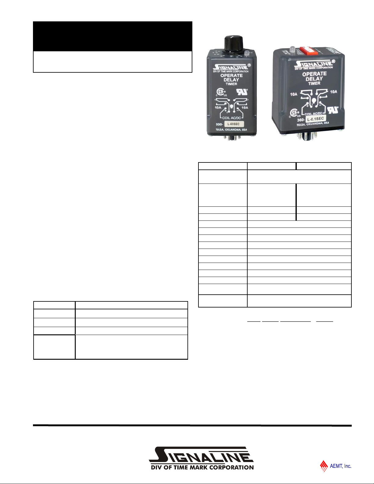
MODEL 330
MODEL 360
Operate Delay Timers
⚫ Solid-State Design
⚫ 10 Amp Relay Contacts
⚫ Multiple Voltage and Timing Ranges
⚫ 5-Year Unconditional Warranty
DESCRIPTION
The Models 330 and 360 Operate Delay Timers are
designed for a wide range of industrial applications.
Examples include automatic and machine tool control
circuits, HVAC circuits, and warm-up delay circuits. The
Model 330 is a DPDT potentiometer (knob-adjust) timer.
The Model 360 is a DPDT, high-accuracy digital input
timer. Solid-state timing circuits in each model drive an
internal electromechanical relay.
Each model is functionally interchangeable. They are
available in a variety of voltage and timing ranges to cover
all possible applications.
An “SG” version of this model is available using silver with
gold flash contacts.
Models 330 and 360 are UL Recognized and CSA
Certified.
UL SPECIFICATIONS*
Models 330 and 360
Input
Voltage (VAC)
Power 3 Watts Max
Output
10-28V AC/DC OR 40-260V AC/DC
240V AC, 10A, Resistive
120V AC, 4A, General Use
240V AC, 2A, General Use
C300, Pilot Duty
SPECIFICATIONS
MODEL 330 (knob adj.) 360 (digital)
Voltage L = 10-28V AC/DC
Timing range 10SEC: 1 - 10 Sec.
Accuracy ± 5% ± 2%
Repeatability ± 2% ± 0.1%
Recycle time 100ms
Operating temp -20°F to 140°F
Contacts DPDT
Contact rating 10A at 240VAC resistive
Transient protection 775V, 80 Joules
Humidity tolerance 0 - 97% w/o condensation
Enclosure material NORYL Plastic
Mounting 8-pin socket (*not included) **
Weight 5 oz.
Agency approval UL Recognized and CSA Certified
Additional Options /C = Custom (Voltage and/or Timing)
Ordering Examples (Model-Voltage-Timing Range [/Options]):
360-H-0.1SEC = Model 360 with a 40-260V AC/DC voltage range
and a timing range of 0.1-102.3 seconds.
330-L-180SEC /SG = Model 330 with a 10-28V AC/DC voltage
range, a timing range of 1-180 seconds, and optional silver with gold
flash contacts.
Contact Time Mark to order a custom programmed unit
60SEC: 1 - 60 Sec.
180SEC: 1 - 180 Sec.
300SEC: 1 - 300 Sec.
H = 40-260V AC/DC
0.1SEC: 0.1 - 102.3 Sec.
1SEC: 1 - 1023 Sec.
1MIN: 1 - 1023 Min.
1HR: 1 - 1023 Hr.
/SG = Silver with Gold Flash Contacts
** order 8-pin socket number 51X120
* Pilot Duty:
120V: Make 15A, Break 1.5A
240V: Make 7.5A, Break 0.75A
11440 Ea s t P i ne S tre e t
Tu l sa , O kla h om a 7 4 11 6
Page 1 of 3 02/2020
© 2020 TIME MARK CORPORATION
MODEL 330 / 360
TIME MARK is a division of
Operate Delay Timers
READ ALL INSTRUCTIONS BEFORE INSTALLING, OPERATING OR SERVICING THIS DEVICE.
KEEP THIS DATA SHEET FOR FUTURE REFERENCE.
GENERAL SAFETY
POTENTIALLY HAZARDOUS VOLTAGES ARE PRESENT AT THE TERMINALS OF THE MODEL 330 OR 360.
ALL ELECTRICAL POWER SHOULD BE REMOVED WHEN CONNECTING OR DISCONNECTING WIRING.
THIS DEVICE SHOULD BE INSTALLED AND SERVICED BY QUALIFIED PERSONNEL.
Installation Instructions
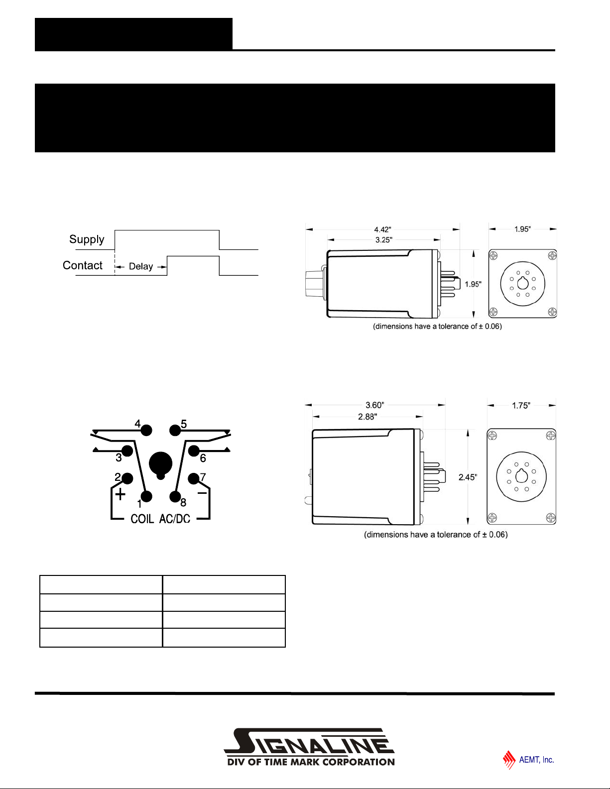
OPERATION
The time delay begins when the supply voltage is applied.
Upon completion of the delay period, the internal relay will
energize, and remain that way until the supply voltage is
removed.
PIN CONNECTIONS
The Models 330 and 360 Operate Delay Timers require a
standard 8-pin socket for mounting, and use a standard
pin configuration. Refer to the pin diagram below, or on
the timer, for terminal connections.
An LED on top of the unit provides
a quick visual indicator of the relay’s status.
Shows No Power Applied
DIMENSIONS - Model 330
DIMENSIONS - Model 360
Green Energized
Red De-energized
Flashing (Green or Red) Relay is Timing
LED Indicator Unit Status
11440 Ea s t P i ne S tre e t
Tu l sa , O kla h om a 7 4 11 6
Page 2 of 3 02/2020
© 2020 TIME MARK CORPORATION

MODEL 330 / 360
TIME MARK is a division of
1
Code: = switch OFF
2 ⚫
= switch ON
4 ⚫
81632 ⚫
64 ⚫
128
256
512
1
Code: = switch OFF
2 ⚫
= switch ON
4
8 ⚫
16
32 ⚫
64 ⚫
128 ⚫
256 ⚫
512 ⚫
Operate Delay Timers
READ ALL INSTRUCTIONS BEFORE INSTALLING, OPERATING OR SERVICING THIS DEVICE.
KEEP THIS DATA SHEET FOR FUTURE REFERENCE.
GENERAL SAFETY
POTENTIALLY HAZARDOUS VOLTAGES ARE PRESENT AT THE TERMINALS OF THE MODEL 330 OR 360.
ALL ELECTRICAL POWER SHOULD BE REMOVED WHEN CONNECTING OR DISCONNECTING WIRING.
THIS DEVICE SHOULD BE INSTALLED AND SERVICED BY QUALIFIED PERSONNEL.
Installation Instructions
ADJUSTMENT PROCEDURE - Model 360
The procedure to determine the switch selections for the
digital Model 360 Operate Delay Timer requires some
simple calculations, which can be completed easily after
the basic steps are explained.
1. Convert the delay time required to minutes, seconds,
or tenths of seconds, depending upon the timing
range of the unit. For example:
2. To set the desired delay period on the timer, just add
e.g. #1: 100 seconds with a 1 second increment
7 hrs, 32 min = (7x60)+32 = 452 minutes
15 min, 2 secs = (15x60)+2 = 902 seconds
6.7 secs = (6.7*10) = 67 tenths of a second
the values of the selected dip switches (beginning
with the largest value first) to total the desired time.
64+32+4 = 100
seconds
e.g. #2: 100 seconds with a .1 second increment
512+256+128+64+32+8 = 1000 tenths of a seconds
WARRANTY
This product is warranted to be free from defects in
materials and workmanship, and is covered by our
exclusive 5-year Unconditional Warranty. Should this
device fail to operate for any reason, we will repair it for
five years from the date of manufacture. For complete
warranty details, see the Terms and Conditions of Sales
page in the front section of the Time Mark catalog or
contact Time Mark at 1-800-862-2875.
11440 Ea s t P i ne S tre e t
Tu l sa , O kla h om a 7 4 11 6
Page 3 of 3 02/2020
© 2020 TIME MARK CORPORATION

TIME MARK is a division of
Have Questions? Call us at (800) 862-2875 and talk to a real live person.
11 4 40 E as t Pi n e Str e et
Tu l sa , O kla h om a 7 4 11 6
02/2020
© 2020 TIME MARK CORPORATION
 Loading...