

Timeguard TRT039N Installation & Operating Instructions Manual
Installation & Operating Instructions
7 Day Digital Programmer
4 Channel – Surface Mount
Model: TRT039N

1
1. General Information
These instructions should be read carefully and retained for further reference
and maintenance.
2. Safety
• Before installation or maintenance, ensure the mains supply to the
programmer is switched off and the circuit supply fuses are removed
or the circuit breaker turned off.
• It is recommended that a qualified electrician is consulted or used for the
installation of this programmer and install in accordance with the current
IEE wiring and Building Regulations.
• Check that the total load on the circuit including when this programmer is
fitted does not exceed the rating of the circuit cable, fuse or circuit breaker.
• To clean use a clean dry cloth only. Do not use any liquid cleaners.
3. Technical Specifications
• 230V AC 50 Hz
• This thermostat is of Class ll Construction and must not be earthed
• Switch Rating: 3(1)A
• Switch Type: Single pole, double throw (SPDT)
for heating zones and hot water,
voltage free contacts
• Connection Type: 3 wire
• Installation Type: Surface mount with wall plate
• Micro Disconnection: Type 1.B control action
• Operating Temperature Range: 0°C to +40°C
• Time Control Periods: 3 per day
• Clock Format: 12hr AM/PM or 24hr
• Summer/Winter Changeover: Day light saving, GMT or BST
• Holiday Mode: 0 to 31 day programme suspension
• Boost Function: 1 or 2 hour for heating zones
and hot water
2
• Battery Backup: 7 day, factory fitted rechargeable
(non-replaceable)
• Illumination: Blue LED illuminated on setting for button
surrounds and display
• CE Compliant
• Dimensions (H x W x D): 90 x 135 x 30mm
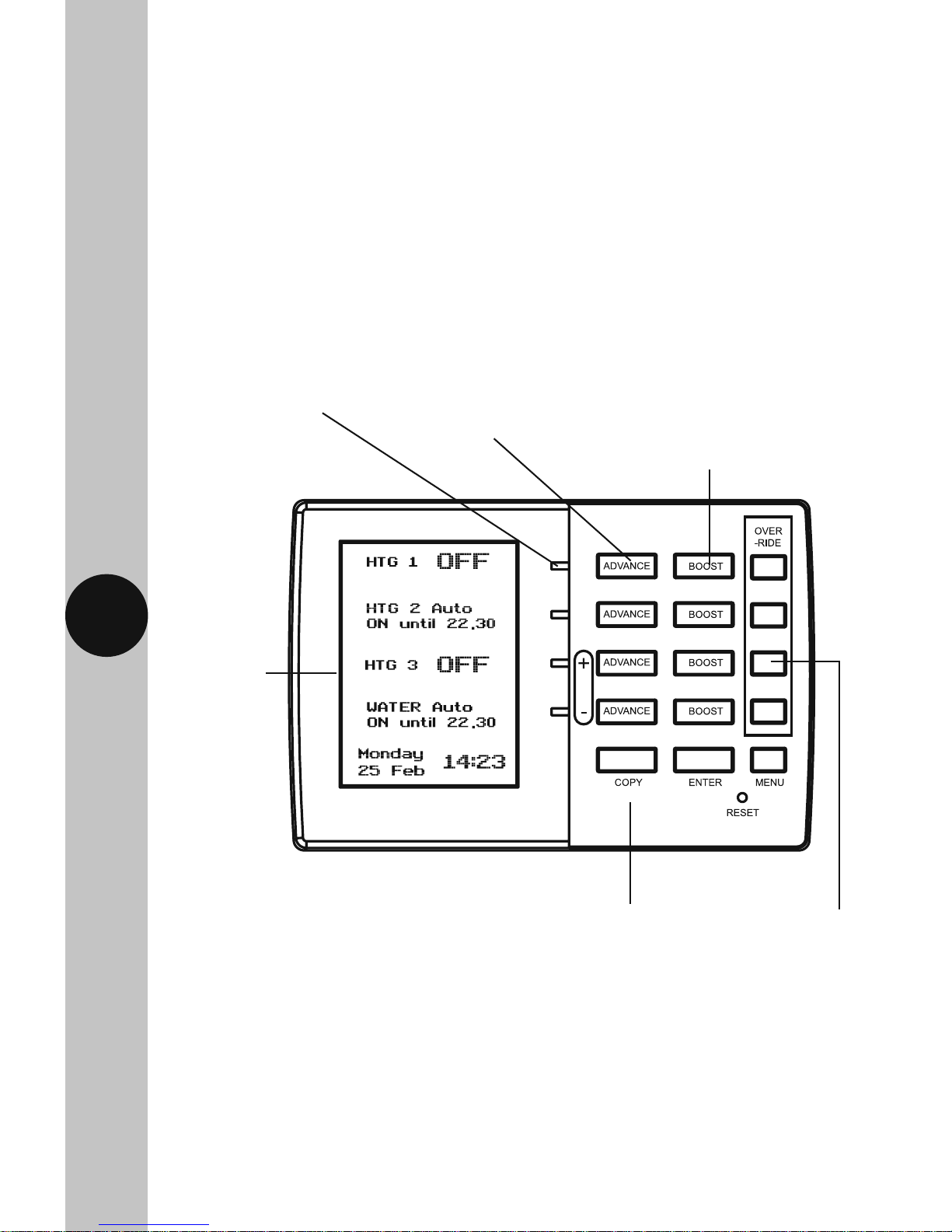
TRT039N Front View
Output LED’s for channel
switch status
12hr am/pm
or 24hr clock
timer display
(illuminated
on setting)
1 and 2 hour boost for central
heating zones and hot water
(illuminates on setting)
Advance button
to next programme
Programme override
for each channel
Flip down cover conceals
setting buttons

3
4. Siting
• The TRT039N should be located at a position which eases wiring runs
and gives good access for programming.
• It should be mounted approximately 1.5m above floor level.
5. Installation
5.1 Ensure the mains supply is switched off and the circuit supply fuses
are removed or the circuit breaker turned off.
5.2 Remove the wall plate from the unit, by undoing the retaining screws,
and pivoting the bottom of the unit outwards. The TRT039N body can
then be lifted off.
5.3 Mark the position of the mounting holes on the wall using the wall plate
as a template. Drill out the mounting holes taking care to avoid any
joists, electrical cables or water/gas pipes that may be hidden beneath
the surface. Insert the rawl plugs into the holes.
5.4 Pass the 230V 50Hz mains supply and load cables through the opening
of the wall plate. Allow sufficient excess cable to wire up the unit, but
not too much to make it difficult to close the unit to the wall plate.
5.5 Fix the wall plate to the wall using the correct mounting screws for the
rawl plugs installed. The retaining screws which secure the unit to the
wall plate should be at the bottom.
5.6 Terminate the cables into the terminal block ensuring correct polarity
is observed and that all bare conductors are sleeved (See section 6.
Connection Diagram). Make sure that the curved washer grips
the conductor.
5.7 To reinstall the unit onto the wall plate, first ensure the wall plate
retaining screws are loosened enough to clear the TRT039N body, then
engage the top of the TRT039N onto the wall plate retaining tabs, and
push firmly downwards and then upwards. There will be some resistance
from the terminals.
5.8 Once in place, secure with the retaining screws making sure not to
over tighten.
4
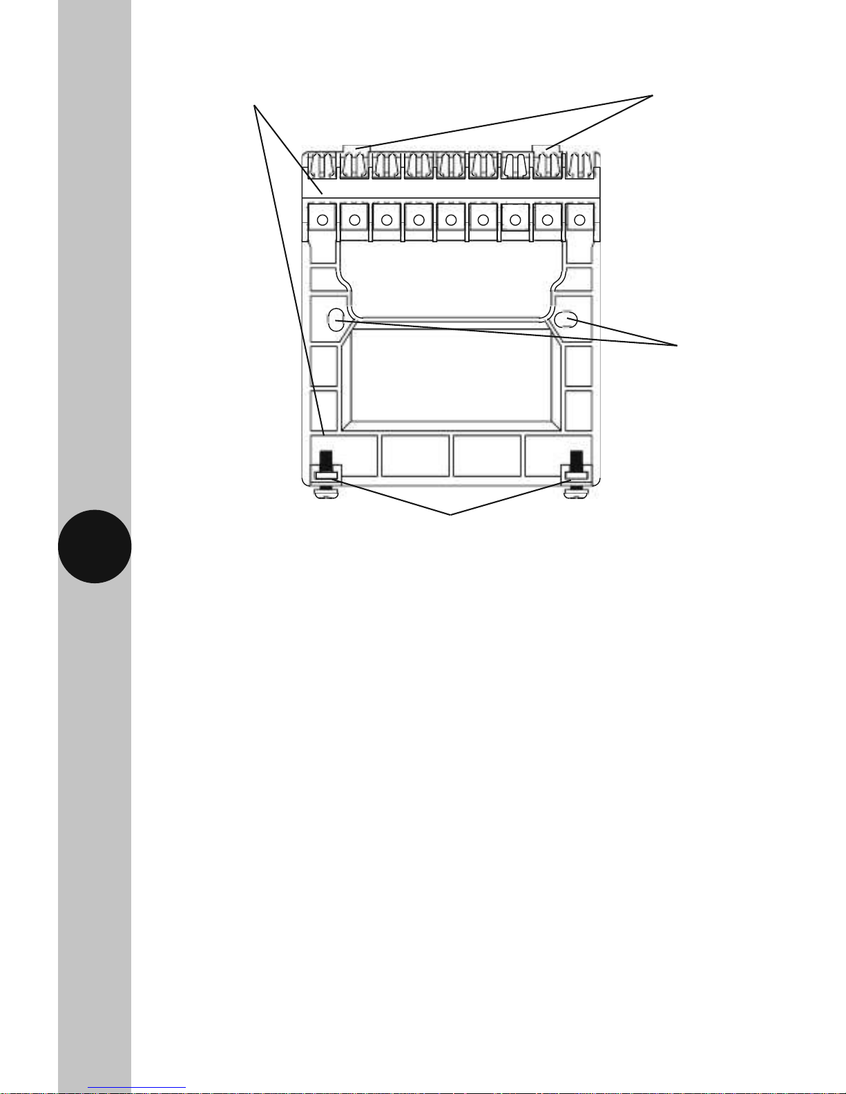
TRT039N Wall Plate
Alternate mounting holes
Wall plate retaining screws
Retaining tabs
Mounting
holes
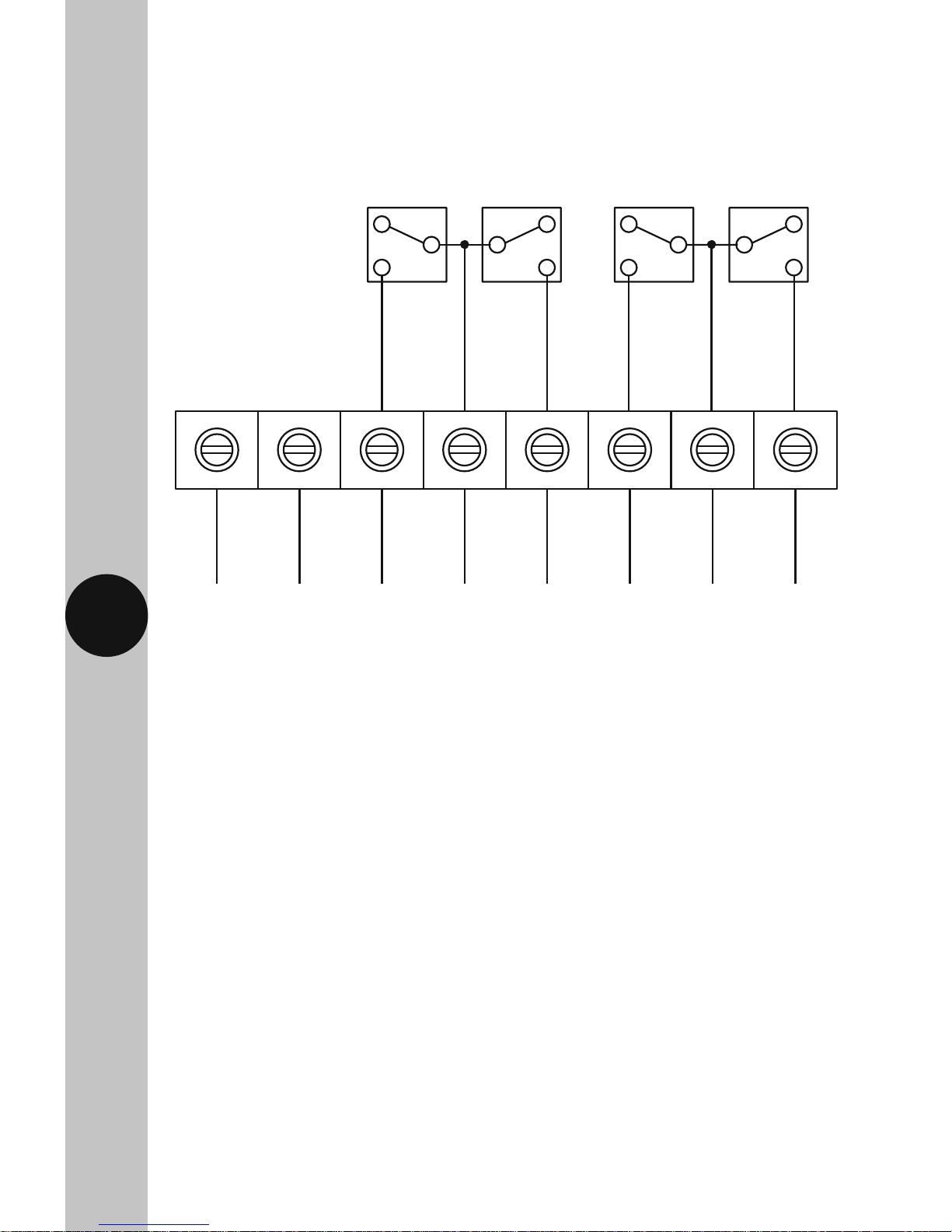
COMONONCOMONNL
N P1 P2 P3 P4 P5L
230V 50Hz
Mains
Supply
Neutral
(Blue or
Black)
P3 ON =
Normally
Open
Contact
–
Switch
Live for
Heating
Zone 2
P1 ON =
Normally
Open
Contact
–
Switch
Live for
Heating
Zone 1
P2 COM =
Voltage
Free
Common
P4 ON =
Normally
Open
Contact
–
Switch
Live for
Hot
Water
P5 COM =
Voltage
Free
Common
ON
P6
P6 ON =
Normally
Open
Contact
–
Switch
Live for
Hot
Water
230V 50Hz
Mains
Supply
Live
(Brown
or Red)
5
6. Connection Diagram
Connect the 230V 50Hz mains supply and load cables to the terminal block
which are marked as follows;
• Note: Check boiler instructions before connecting.
 Loading...