


360º SURFACE MOUNT CEILING PIR LIGHT CONTROLLER
Cat No. SLW360
G N I AT R E P O & N O I AT L L TA S N I S N O I T C U R T S N I
Introduction
The SLW360 utilises passive infrared technology to detect heat radiation of moving human bodies.Upon detection, the attached lighting load will illuminate for a user-determined time period. An integral daylight sensor ensures day or night-only operation.
|
Important Information: Light Pollution and |
|
|
considerate Lighting |
|
|
Please be aware of the annoyance over-lighting an area |
|
|
can cause to your immediate neighbours. Light |
|
|
pollution caused by incorrectly installing a unit or |
|
|
over-lighting an area can be limited by carefully |
|
|
considering the location and position of your unit |
|
|
before installation. The light spread on all halogen |
|
|
floodlights can be reduced by angling the floodlight |
|
|
downwards on the mounting bracket. This will also |
|
|
concentrate the light on your property and limit the |
|
|
potential inconvenience of the light shining into your |
|
|
neighbours windows etc. |
|
1 |
||
Please see Selecting a Location for information on |
||
choosing the optimum location for any security light |
controlled by this unit.
|
|
A |
|
Side View |
|
|
|
|
|
|
B |
|
|||||
|
|
|
|
|
|
|
|
|
|
|
|
|
|
|
|
|
|
|
|
|
|
|
|
|
|
|
|
|
|
|
|
|
|
|
|
|
|
|
|
|
|
|
|
|
|
|
|
|
|
|
|
|
|
|
|
|
|
|
|
2.5m |
|
|
|
|
|
|
|
|
|
||
|
|
|
|
|
|
|
|
|
|
|
|
|
|
|
|
||
|
|
|
|
|
|
|
|
|
|
|
6m |
|
|
|
|
||
|
|
|
|
|
|
|
|
|
|
|
|
|
|
||||
|
|
|
|
|
|
|
|
|
|
|
|
|
|
|
|
|
|
|
|
|
|
Side View |
|
|
|
|
|
|
|
|
|||||
|
|
|
|
|
|
|
360º |
|
|
Less sensitive |
|||||||
|
|
|
|
|
|
|
|
|
|
|
|
|
|
|
|
||
|
|
|
|
|
|
|
|
|
|
|
|
|
|
|
|
|
|
|
|
|
|
|
|
|
|
|
|
|
|
|
|
|
|
|
|
C |
Lens Mask |
|
|
|
|
|
|
D Mounting hole |
|||||||||
|
|
|
|
|
|
Restrict short detection |
|||||||||||
|
|
|
|
|
|
|
|
||||||||||
More sensitive
Restrict long detection |
|
Restrict detection directly under sensor |
Mounting hole |

E |
Twist cover anti-clock wise |
Align marks on moulding
Remove decorative cover
F
 2
2
Time On |
Lux - |
setting |
Dusk/Dawn |
|
setting |
H |
Switched |
L1 |
Load |
L2 |
OUT |
Factory fitted
bridge wire REMOVED  L
L
N
E
Mains Supply IN
In the above illustration:
-the L1 L2 terminals are used to control a DC load or if the load uses a different phase or voltage supply from the AC mains in.
-factory fitted bridge must be removed to isolate L1 & L2 terminals from AC mains in.
G |
Switched |
L1 |
Load |
|
OUT |
Factory fitted bridge wire
L
N
E
Mains Supply IN
In the above illustration:
-4 core cable may be used
-there is no external junction box
-A bridge is provided, prewired to bridge across live supply from AC mains to the output load
I Ceiling mount assembly method.
Wall plugs x 2. 
Sponge gasket. |
|
Fit if mounting |
|
the unit outdoors. |
|
Discard if fitting |
|
indoors |
Cable |
Mounting |
gasket |
|
|
Plate |
|
Sensor |
Mounting |
|
screws |
|
Top cover |

Parts included
•PIR Sensor unit.
•Instruction manual. Please keep safe for future reference.
•Accessory Pack. Includes 2 x wall plugs, 2 x wall fixing screws, 1 x lens mask sticker.
•1 x outdoor mounting sealing gasket.
•1 x incoming/outgoing wire gasket.
Tools and parts needed
•3 core flexible cable.
•Electric/hand-held drill & bits.
•Terminal or Electricians screwdriver.
•Large slotted/philips screwdriver.
•Wire cutters suitable mains interconnect cable.
|
This product is suitable for indoor or outdoor use. |
|
Connected load must not exceed maximum |
3 |
2000W filament/incandescent or 500W fluorescent/low |
energy lighting. |
|
Do not attempt to install during wet weather, if you are |
suffering from nausea or dizzy spells or on medication with similar side effects. If in any doubt, consult a qualified electrician.
Not suitable for use with discharge lighting.
Selecting a location
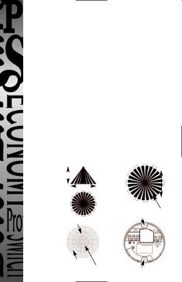
The motion detector has a number of detection zones, at various vertical and horizontal angles as shown (see diagram A).
A moving human body needs to cross/enter one of these zones to activate the sensor. The best all-round coverage is achieved with the unit mounted at the optimum height of 2.5m.
Careful positioning of the sensor will be required to ensure optimum performance. See diagram A detailing detection range and direction.
 Loading...