

Page 1
UNDERFLOOR HEATING
CONTROLLER
Cat. No TPT44
INSTALLATION & OPERATING INSTRUCTIONS
Page 2

General
The ProgramaSTAT TPT44 combines the elements of
timeswitch and room thermostat in a single compact,
economical and stylish unit. Back up is provided to
retain programme information in the event of a
power failure.
The TPT44 controls the room temperature to a
comfort level when required and to a set-back
temperature at other times. It does this using
an internal temperature sensor. The set-back
temperature can be set to 10°C for frost protection
or much higher when elderly or infirm are occupying
the room. The floor temperature is monitored with
an underfloor probe (included) and is limited at
a user adjustable temperature which must not
be set higher than 30°C.
1
Siting
The TPT44 ProgramaSTAT should not be installed in
a wet area. Further siting instructions are given in
the Thermolay cable and mat instruction leaflet.
If there is additional heating in the room do not
position the TPT44 directly above it.
Page 3

Installation
We recommend this unit be fitted by a
qualified electrician.
Install in accordance with wiring and current
building regulations.
Please read the instructions carefully. If in doubt,
contact the Timeguard Helpline 020 8450 0515.
The TPT44 underfloor heating controller is designed
to fit onto either a BS4662 recessed single box or a
BS5733 surface mount single box. The minimum box
depth required is 32mm. The ideal mounting height
is at eye level for the shortest person who is likely
to programme the unit. For details of the installation
of the temperature probe and heating cable or mat
see the Thermolay instruction leaflet.
2
Switch OFF the mains to the controller.
Remove the thermostat surround by pulling
forward on the surround. Use a small screwdriver as
a lever to remove the surround when the thermostat is
fixed on the wall. Cut the cable tails of the temperature
probe and heating mat or cables to length and strip
sleeving and insulation as required. Identify the wires
and locate according to figure 1. Supply cable with
a minimum of 2.5mm
screw terminals onto the wires and form the cables.
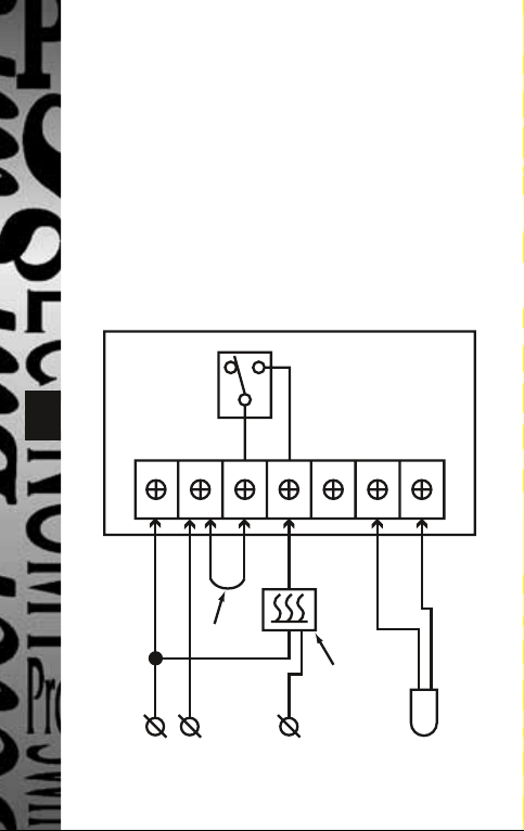
Ensure that the link shown between terminals 2
and 3 in Fig. 1 is in place. Offer the unit up to the
wall box forming the cables as required, finally locating
and tightening up the fixing screws supplied.
Snap the surround back into position.
To test the unit is operating set the temperature to
30ºC as described in
2
must be used. Tighten the
‘
Manual Temperature Setting A.
Page 4
Temporary temperature override’. After a few seconds
the Heating ON indicator will show. Wait for 1 hour for
a wood under floor or up to 5 hours for an uninsulated
concrete floor (the warm-up time for uninsulated
concrete will be substantially reduced when the moisture
has been driven out of the concrete during the first few
heating cycles) and feel if the floor starts to warm.
If it does not, check the connections and carry out
the checks on the mat or cable installation instructions.
Wiring Connections
TPT44
3
123
LINK
LNE
4
COM NONL
56
Heating mat
or cable
230V AC
SENSOR
Fig. 1
Page 5

Earthing
The TPT44 itself does not require to be earthed.
The screen around the flying lead (cold cable) from the
Thermolay mat must be earthed to the box terminal.
This also applies to the screen at each end of the
Thermolay cable, both of which must be earthed
in the same way.
Programming
Power on and reset
When first switched on the TPT44 has a default program
set which is comfort mode from 7.00am to 10.30pm.
In case of a power cut the unit will remember the
program but the time will need to be reset.
To reset the unit to its original program using a narrow
blunt object (such as a paper clip) press and hold the
4
‘Reset’ button through the small hole then press and
hold ‘Set’ and release ‘Reset
’.
Page 6

Heating ON
Comfort
mode
Set-Back
mode
Time dial – 30 minute segments
Program mode
Time
Manual mode Temperature
5
Time Setting
1. Press ‘Prog’ once, the time indicator now flashes,
Program mode indicator
2. Press
3. Press
‘
+’ or ‘–’ to adjust the time.
‘
Set’ 5 times to exit, or wait 15 seconds for
the unit to auto-exit to the normal run mode.
‘
’ shows on the dial.
Floor limit
Fig. 2
Page 7

Program Setting
Example:
If you want to set 2 different programs,
i.e. ON at 6am and OFF at 9.30am and then
in the evening ON at 17.30 and OFF at 22.30.
1. Press the
start to flash. (In the Programming mode you will
see a
if there is no activity within 15 seconds the unit
will exit the Programming mode and will start
to run in the Normal Operating Mode).
2. Press the
show
at the 24 hour mark. (You will need to make
sure that at this point none of the segments
6
are highlighted. If there are segments visible,
press the
and you are back around to the 24 hour mark).
3. You will now be in the Set Back mode with the
symbol showing on the display. Using the
advance to 6am and press the
4. You will now be in the Comfort mode with the
symbol showing on the display. Again using the
button highlight the segments on the Time-Zone
indicator until you reach the OFF time (9.30am).
5. Press
with the
advance to the next ON time. In this case at 17.30.
6. Press
with the
advance to the next OFF time. In this case 22.30.
‘
Prog’ button once and the time will
‘
’ on the top right hand side of the display,
‘
Set’ button once. The time now will
‘
0:00’ flashing and the Time-Zone indicator
‘
–’ button until all have disappeared
‘
Prog’ button once.
‘
Prog’ to change the mode back to Set Back
‘
’ symbol showing. Using the ‘+’ button
‘
Prog’ to change the mode back to Comfort
‘
’symbol showing. Using the ‘+’ button
‘
‘
+’ button
‘
‘
+’
’
’
Page 8

7. Wait 15 seconds until the screen has returned
to Normal Operating Mode.
Once you have done both programs you will see
the segments highlighted which indicate the
Comfort Temperature and the blank segments
which indicate the Set Back Temperature.
Note: The Time-Zone indicator is one
segment on the time dial (24 hour clock).
The time increases/decreases by 30 mins
every time you press the
‘
+’ or ‘–’ button.
Temperature Settings
Example:
Setting Comfort Temperature to 28°C
(this is the normal running temperature
7
for your programmed times)
Setting the Set Back Temperature to 16°C
(this is temperature that will be controlled
outside of your programmed times)
The Floor Temperature Limiter should not
be set to a temperature higher than 30°C.
1. Press the
button twice. You will see the
which represents the Comfort temperature.
2. Using the
temperature to 28°C.
3. Press the
the
the Setback temperature.
4. Using the
temperature to 16°C.
‘
Prog’ button once, followed by the ‘set’
‘
’ symbol flashing
‘
+’ or ‘–’ button, advance the
‘
Set’ button once. You will see
‘
’ symbol flashing which represents
‘
+’ or ‘–’ button, advance to the
Page 9

5. Press the
the
the Floor Temperature Limiter.
6. Using the
temperature to 30°C (maximum).
7. Press the
to Normal Operating Mode.
‘
Set’ button once. You will see
‘
Ø’ symbol flashing which represents
‘
+’ or ‘–’ button, advance the
‘
Set’ button once to return
Manual Temperature Setting
A. Temporary temperature override.
1. Press ’+’ or ’–’. The ’
temperature flash.
2. Press the ’+’ or ’–’ key to set the temperature.
3. Press ’Set’ key once to confirm and the ’
8
indicator flashes every 3 seconds. It will stay in
this Temporary temperature override mode until the
next change from Comfort to Set-Back or vice versa.
4. To exit the temporary override at any time
press ’Set’ again.
B. Hold function in hours.
1. Press ’+’ or ’–’, the ’
temperature flash.
2. Press ’+’ or ’–’ key to set the temperature.
3. Press ’Prog’ key, ’1H’ indicator displayed.
4. Press ’+’ or ’–’ key to set the number of running
hours from 1 to 24. The ’
every 3 seconds.
5. To cancel this mode press the ’Set’ button.
’ indicator and the
’ indicator and the
’ indicator flashes
’
Page 10

Lock Function
1. Press and hold ’Set’ key for 5 seconds,
’LOCK’ displayed, the keyboard lock is on.
2. Press and hold ’Set’ key for 5 seconds again,
’ULOC’ displayed, the keyboard lock is off.
Read the Floor Temperature
Press ’Set’ key once, the floor temperature is displayed
and will go back to the air temperature after 5 seconds.
Specifications
Operating temp: -10°C to 40°C
Operating voltage: 220 – 240V AC, 50Hz
9
Switch capability: 16A resistive, 3A inductive
Temp probe flying lead: 4m length
Temp control range: 6°C to 30°C
Temp accuracy: ±1°C (at 20°C)
Control type: Normally open, voltage free
EC directives: Conforms to latest directives
Dimensions (mm): 84 (H) x 84 (W) x 27 (D)
Supplied probe: 100 k
at 25°C
Page 11

3 Year Guarantee
In the unlikely event of this product becoming faulty due
to defective material or manufacture within 3 years of
the date of purchase, please return it to your supplier
in the first year with proof of purchase and it will be
replaced free of charge. For the second and third years
or any difficulty in the first year telephone the helpline
on 020 8450 0515.
Note: A proof of purchase is required in all cases.
For all eligible replacements (where agreed by
Timeguard) the customer is responsible for all shipping/
postage charges outside the UK. All shipping costs are
to be paid in advance before a replacement is sent.
10
Page 12

For assistance with the product please contact:-
HELPLINE
020-8450-0515
or email helpline@timeguard.com
For a product brochure please contact:
Timeguard Ltd.
Victory Park, 400 Edgware Road,
London NW2 6ND Tel: 020-8452-1112
or email csc@timeguard.com
A Group company
67.058.213 (Issue 4)
 Loading...