

Page 1

BATTERY POWERED
DETECTOR/
TRANSMITTER
Cat No. TLTXDCB
INSTALLATION & OPERATING
INSTRUCTIONS
Page 2

Introduction
The TLTXDCB Battery Powered Detector/Transmitter is
part of the Timeguard range of PIR products which
communicate by radio frequency (r.f.) signals. This
enables substantial amounts of wiring to be eliminated
which is particularly useful in long wiring runs and
coverage of outbuildings.
It is a combined PIR detector and r.f. transmitter which is
battery powered. It detects moving body heat and
transmits (sends) a signal to receivers in the system that
have been programmed to respond to its coded signal
causing their lights to turn on.
In the following instructions products with catalogue
numbers including TX (ones that send information about
PIR detection) are referred to as Tx units and products
1
with catalogue numbers including RX (ones that receive
information about PIR detection) are referred to as Rx units.
A
Top
View
2.5m
B
Side
View
C
180º
12m
D
Less
sensitive
Lens Mask
Restrict long detection
Restrict RHS detection
Restrict short detection
Restrict LHS detection
2
More
sensitive
Page 3

Parts included
• PIR Sensor unit.
• Instruction manual. Please keep safe for future
reference.
• Accessory Pack.
Tools and parts needed
• Electric/hand-held drill & bits.
• Terminal or Electricians screwdriver
• 1 x 9V alkaline PP3 Battery
Unit can be used indoors or outdoors.
Selecting a location
For optimum performance, mount at 2.5m (8ft)high.
The detector can be pointed in any direction as long as
it is within 100m of the receivers it is to be used with.
The detector can detect motion up to 12m within a 180
2 3
degree radius.
The detector moves up or down, left or right to change
the coverage area.
Keep in mind the sensor is most sensitive to movement
across its field of vision.
The motion detector has a number of detection zones,
at various vertical and horizontal angles as shown (see
diagram A). A moving human body needs to cross/
enter one of these zones to activate the sensor.
Careful positioning of the detector will be required to
ensure optimum performance. See diagram A.
The detector is more sensitive to movement ACROSS
its field of vision than to movement directly TOWARDS
it (see diagram B). Therefore position the unit so that
the sensor looks ACROSS the likely approach path.
Avoid positioning the sensor where there are any
sources of heat in the detection area (extractor fans,
Page 4
tumble dryer exhausts etc.).
Reflective surfaces (ie pools of water or white-painted
walls) and overhanging branches may cause false
activation under extreme conditions.
During extreme weather conditions the motion
detector may exhibit unusual behaviour. This does not
indicate a fault. Once normal weather conditions return,
the detector will resume normal operation.
When siting Rx units that will need to work with the
TLTXDCB the signal reception range will be less than
100m if walls or chain link fences come between the
Tx and Rx units - if there is any doubt whether
communication will take place make temporary
installations before programming.
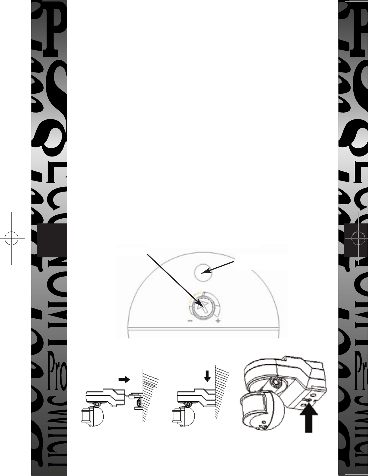
E
View on Underside of Sensor Head
3 4
Dusk/Dawn
F
Photocell
(Daylight sensor)
Page 5

Installation
Release screw on underside of unit and remove wall
plate from main body of sensor, this screw is captive,
do not remove. (Fig F)
Mark position of the fixing holes. (Fig D)
Drill the holes. Insert the wall plugs into the holes.
Fit a 9V PP3 alkaline battery.
Fix the mounting plate to the wall. Take care not to
overtighten the screws to prevent damage to the
mounting plate. If using a power screwdriver, use the
lowest torque setting.
Fit PIR to wall bracket and secure by fixing screw. (Fig F)
Setting up
In the u
defectiv
of purc
with pr
For ye
4
Walk Test Procedure
The sensor will rotate from left to right, and tilt forward
or backward. Adjust the sensor to point in the required
direction. (note diagram B)
The unit can be set up in daylight or at night. Remove the
sticker covering the photocell (daylight) sensor. For
daylight set up, leave the Dusk/Dawn adjuster at the sun
end. For nightime operation set the Dusk/Dawn adjuster
about two thirds of the way toward the moon end.
Walk in front of the Sensor, keeping an eye on detector’s
LED (diagram F). It will flash red when sensing an object
and transmitting a signal. (The detector will continue to
sense motion if present, but will only transmit a signal
and flash the LED every 5 seconds.)
Range may be reduced by angling the detector
downwards.
Check to make sure the detector covers the desired area
and adjust to suit your installation.
Page 6

Programming
To be operated by the Timeguard Wireless Transmitters,
the Timeguard Wireless Receivers must learn the
Transmitters unique code. This is achieved
automatically by the following procedure.
1. Press the Rx unit’s PROGRAM button for 1 to 2
seconds while Rx unit is powered. Be careful not to
press for much longer than 2 seconds or you may erase
all existing memorised codes. The light will go ON
indicating it is in Program Mode and will remain on up
to 5 minutes. (If programming a Chime Receiver it will
make a “beep” and the LED will flash indicating it is
program mode)
2. Activate the Tx unit’s PIR detector to send a signal to
the Rx unit by walking into its detection zone. The
5
TLTXDCB’s LED flashes red indicating motion has
been sensed and a signal has been transmitted. The
Tx unit will to send its coded signal to the Rx unit and
the light will go off. (if using a Chime receiver a “beep”
will sound indicating it has been coded with the
Tx units signal).
3. The Rx unit has acknowledged the Tx unit’s signal
by turning the lights OFF. The Rx unit is now
programmed to respond to the Tx unit. No other Tx
unit can activate this RX unit unless it is programmed
to do so.
4. If the lights did not go OFF or the Chime did not
“beep” the Rx unit was not picking up a signal. Check
the radio signal path between the Tx and Rx units for
any obstructions (walls, support beams, chain link
6
fences etc).These can block radio signals and interfere
with signal transmission. Up to 5 further Rx units may
now be introduced to the Tx unit if required.
Page 7

PLEASE NOTE:- SEE THE SEPARATE INSTRUCTION
MANUALS FOR THE RECEIVER PRODUCTS TO
UNDERSTAND HOW TO PROGRAM AND ADJUST
THAT SPECIFIC Rx UNIT.
Low Battery Indication
The LED will flash on and off twice at every detection
if the battery voltage is low.
Replace the battery as soon as possible.
Troubleshooting guide
Problem
• TLTXDCB LED will not
activate when motion is
detected.
6 7
• Tone/Light comes on in
daylight
Possible Cause/Solution
1. Isolation switch is turned
off.
2. Adjust sensor to cover
desired area.
3. Photocell determines it is
daylight.
Adjust Dusk/Dawn control
or move away from light
source.
1. Label not removed from
detector’s photocell.
Remove label
2. Tx unit installed in dark
location. Adjust Dusk/Dawn
control or re-position Tx unit.
Page 8

Problem
Possible Cause/Solution
• Light flashes on and off
twice when activated.
• Tone/Light activates for no
apparent reason
• Light Stays on at night
This is the low battery
signal. Replace
transmitter battery.
Check area for false
activation from heat or
reflective source. Re-aim
sensor if necessary.
1. Check area for false
activation from heat
or reflective source. Re-aim
sensor.
2. Receiver is in Manual
Override mode.
Flip wall switch off then on
again within 2 seconds to
place back in Auto Mode
7 8
• Tone/light activates
irregularly when motion is
sensed
1. Sensor is too far from
Receiver. move closer
2. Re-aim Sensor for
optimum motion
sensitivity. See diagram B.
Page 9

Technical specifications
Detection Range:
Detection Angle:
Power Supply:
Dusk Level Adjustment:
Environmental Protection:
Transmission Range:
Conforms to Directive:
Up to 12 metres
180º
1 x 9V PP3 alkaline battery
Day and night or night only
operation
IP44 (suitable for outdoor use)
Up to 100m (varies with
surrounding structures)
89/336/EEC
8
Page 10

5 Year Guarantee
FIVE YEAR
GUARANTEE
5
In the unlikely event of this product becoming faulty due to
defective material or manufacture within 5 years of the date
of purchase, please return it to your supplier in the first year
with proof of purchase and it will be replaced free of charge.
For years 2 to 5 or any difficulty in the first year telephone
the helpline on 020 8450 0515.
Victory Park, 400 Edgware Road,
HELPLINE
020-8450-0515
For a product brochure please contact:
Timeguard Ltd.
London NW2 6ND
020-8452-1112
or email csc@timeguard.com
 Loading...