

Page 1

Weathersafe Vision
Installation & Operating Instructions
Page 2

IP66 Products covered by
these instructions
TGVL01 Single Gang 2-Way Switch [SP] 10AX
(Fluorescent rated)
TGVL02 Twin Gang 2-Way Switch [SP] 10AX
(Fluorescent rated)
TGVL03 Single Gang Bell Push Switch [SP] 10AX
(Fluorescent rated)
TGVL05 Single Gang Switch [DP] 20AX
(Fluorescent rated)
TGV101N Single Gang Socket Switched 13A
TGV201N Twin Gang Socket Switched 13A
TGV104N Single Gang RCD Fused Spur 13A
TGV204N Twin Gang RCD Socket Switched 13A
(Passive/Latching)
1
TGV205N Twin Gang RCD Socket Switched 13A
(Active/Non-Latching)
TGV103N Single Gang Switched Fused Spur 13A –
with Neon
1. General Information
These instructions should be read carefully and retained for further
reference and maintenance.
All Weathersafe Vision products need to be fitted with waterproof
cable and conduit entries to maintain their IP rating once installed.
2. Safety
• Before installation or maintenance, ensure the mains supply to
the switch, socket, spur or bell push unit is switched off and the
circuit supply fuses are removed or the circuit breaker turned off.
Page 3

• It is recommended that a qualified electrician is consulted or used
for the installation of this IP66 rated switch, socket, spur or bell
push unit and install in accordance with the current IEE wiring
and Building Regulations.
• Check that the total load on the circuit including when this
switch, socket, spur or bell push unit is fitted does not exceed the
rating of the circuit cable, fuse or circuit breaker.
• Electricity can be dangerous; the use of an RCD should not be
regarded as a substitute for basic electrical safety precautions.
• Always test the RCD before use. If the test procedure is not
completed satisfactory or an appliance continues to trip the RCD
seek professional advice and switch off the appliance.
• To clean, use a clean dry cloth only. Do NOT use any liquid cleaners.
• During use warming of the enclosure is normal.
Wiring tests – Important (TGV104N, TGV204N & TGV205N)
• Remove this product from the circuit if carrying out tests (as
2
described in the IEE Wiring Regulations) for earth loop impedance,
prospective short circuit current and insulation resistance.
• Use the enclosed warning label to ensure this is carried out.
3. Technical Specifications
General
• Voltage: 230V AC 50Hz
• IP Rating: IP66
• All products in the range comply with the low voltage directive
2014/35/EU and where relevant the EMC directive 2014/30/EU
and ROHS directive 2011/65/EU.
• CE Compliant
Page 4

Switches (TGVL01, TGVL02, TGVL03, TGVL05)
• Backlit neon (illuminates switch for dark areas)
• Rocker Switch Rating: 13Amp (3kW) 10AX
• Operating temperature range: -5° to 55°C
• Complies with: BS EN 60669
Sockets (TGV101N & TGV201N)
• Individual power ‘ON’ Neon Indicators
• Lockable cover facility
• Operating temperature range: -5° to 55°C
• Complies with: BS1363
RCD’S (TGV104N, TGV204N, TGV205N)
• Lockable cover facility
• Rated trip current: 30mA
• RCD Type: Double pole, suitable for
3
2 and 3 wire applications
• Breaking capacity: 250A (Earth leakage)
• Through fault withstand: 1500A
• Trip Speed: Less than 40msec at 150mA
residual current
• Classification: TGV104N – Latching (Passive)
TGV204N – Latching (Passive)
TGV205N – Non-latching (Active)
• Operating temperature range: -5ºC to 40ºC
• Complies with: BS7288 & BS1363
Fused Spur (TGV103N)
• Power ‘ON’ Neon indicator
• Lockable cover facility
• Operating temperature range: -5° to 55°C
• Complies with: BS1363
Page 5

4. TGVL01, TGVL02, TGVL03, TGVL05
Installation
1. IMPORTANT Switch off the electricity at the fuse box by removing
the relevant fuse or switching off the circuit breaker before
proceeding with the installation.
2. Remove the black coloured rocker switch from the faceplate
pivot support joints using a suitable flat ended screwdriver.
Using a Philips screwdriver, separate the faceplate from the back
box by removing the four tapped screws located in each corner.
See figure 1.
Backlit neon
4 5
Face plate pivot
support joints
3. Using the back plate as a template mark the position for the
holes. Note the back plate must be mounted in the correct
orientation, following the ‘TOP’ marking inside the back plate.
If the mounting position desired is uneven use a sheet of
marine ply as a base plate and fit the back box.
4. Drill the wall using a 4mm Ø drill bit making sure not to infringe
or compromise any gas, water pipes or cables. Insert the rawl
plugs into the holes.
5. The drain feature must be drilled out using a 5mm drill if the top
or side entry conduit is used. Opening this drain hole will reduce
the IP rating of the product. Remember – open out the lower
drain feature only.
Tapped screws
Figure 1
This applies to the
following models:
TGVL01, TGVL02,
TGVL03 & TGVL05
Page 6

6. Cut out the knock-out entry point by carefully scoring the groove
carefully with a sharp knife and using a small hammer for
tapping off the entry point. If conduit is not going to be used,
a waterproof cable with suitable IP rated 20mm glands will be
required to maintain the overall IP rating. If the bottom entry
conduit is used, there must be adequate drainage from the lowest
point of the conduit.
7. Follow suit using the same method depicted in stage 6 to create
an exit point for the output supply cable to follow through on.
8. Secure the back box to the wall using suitable screws
for the rawl plugs installed.
Ensure that the back box is correctly orientated following
the ‘TOP’ marking which is labelled inside.
9. Pass though the 230V AC 50Hz mains supply cable and secure
the cables tightly to their respective terminals. Ensure that all bare
conductors are sleeved and that correct polarity is observed; see
5 6
figure 2 for the appropriate wiring method. Note that if metal
conduit is being used the earth continuity between the conduits
must be maintained.
10. Once the mains supply is connected to the correct terminals,
mount the face plate over the back box aligning the four screws
from the face plate to the four mounting holes on the back box.
Tighten until secured.
11. Once the face plate and back box have been mounted clip the
hinge of the rocker switch to the pivot support joints of the face
plate and push until even on both sides.
Page 7
230V 50Hz
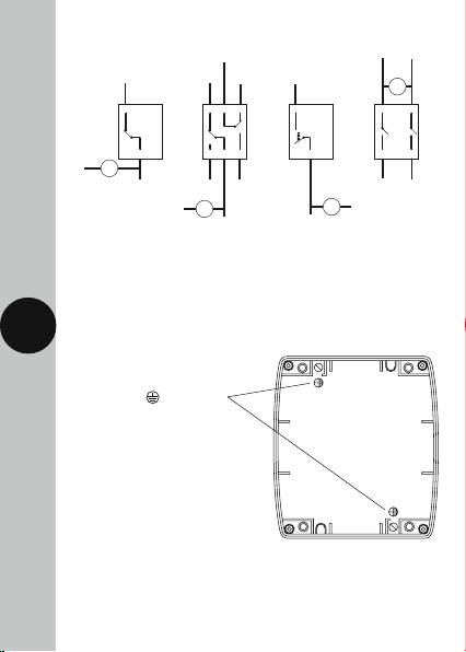
4.1 TGVL01, TGVL02, TGVL03, TGVL05 Wiring Diagrams
Figure 2
Switched
Live to lamp
A1 B1
Live in
Normally
closed
C
A1 B1
Switched
Normally
Live to lamp
closed
C
230V 50Hz
Live in
Neon
C B1
A1CA1 B1
Neutral in
L
A2 B2
Neon
Neutral
230V 50Hz
Live in
TGVL01
If a local neutral is required to give permanent indication of switch
position using the neon supplied, or for wiring purposes, then use one
of the earth terminals shown in figure 3 as a neutral wiring terminal.
6 7
Note: This is the only way the neon should be connected.
One of these two terminals
marked earth
as a neutral terminal.
LA2 B2
Normally
Normally
open
open
Neon
Neutral
230V 50Hz
Live in
TGVL02 TGVL03 TGVL05
can be used
LA2 B2
230V 50Hz
Live in
LA2 B2
Neon
Neutral outLive out
Neutral
Figure 3
TGVL01, TGVL02, TGVL03
Earth Terminal Positions
Page 8
5. TGV101N, TGV201N & TGV103N
Installation
1. IMPORTANT Switch off the electricity at the fuse box by removing
the relevant fuse or switching off the circuit breaker before
proceeding with the installation.
2. Using a Philips screwdriver, separate the faceplate from the back
box by removing the four tapped screws located in each corner.
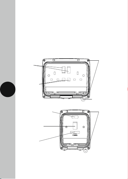
See figure 4 & 5 for your chosen product.
ON/OFF
switches
Individual
backlit neon
indicators
7 8
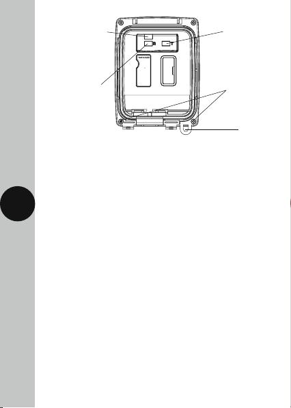
Neon status indicator
ON/OFF switch
Fuse socket
Tapped screws
Figure 4
Features apply to
both TGV101N
and TGV201N
Lid clip for padlocks
Tapped screws
Figure 5
TGV103N
front plate
Page 9
3. Using the back plate as a template mark the position for the
holes. Note the back plate must be mounted in the correct
orientation, following the ‘TOP’ marking inside the back plate.
If the mounting position desired is uneven use a sheet of marine
ply as a base plate and fit the back box.
4. Drill the wall using a 4mm Ø drill bit making sure not to infringe
or compromise any gas, water pipes or cables. Insert the rawl
plugs into the holes.
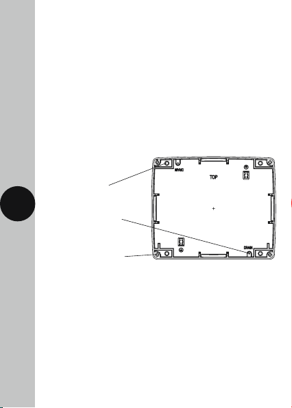
5. The drain feature must be drilled out using a 5mm drill if the top
or side entry conduit is used. Opening this drain hole will reduce
the IP rating of the product. Remember – open out the lower
drain feature only, see figure 6.
Figure 6
4x fixing holes for
no. 8 wood screws
8
Drain feature, use only
lower if required
Front cover fixing holes
6. Select the required entry point by unscrewing the appropriate seal
located on all four sides of the back box. If conduit is not going to
be used, a waterproof cable with suitable IP rated 20mm glands
will be required to maintain the overall IP rating. If the bottom
entry conduit is used, there must be adequate drainage from the
lowest point of the conduit.
7. Follow suit using the same method depicted in stage 6 to create
an exit point for the output supply cable to follow through on.
8. Secure the back box to the wall using suitable screws for the rawl
plugs installed. Ensure that the back box is correctly orientated
following the ‘TOP’ marking which is labelled inside.
Page 10
9. Pass though the 230V AC 50Hz mains supply cable and secure
the cables tightly to their respective terminals ensuring that all
bare conductors are sleeved and that correct polarity is observed,
see figure 7, 8 or 9 for the appropriate wiring diagram of your
chosen product. Note that if metal conduit is being used the earth
continuity between the conduits must be maintained.
10. Once the mains supply is connected to the correct terminals,
mount the face plate over the back box aligning the four screws
from the face plate to the four mounting holes on the back box.
Tighten until secured.
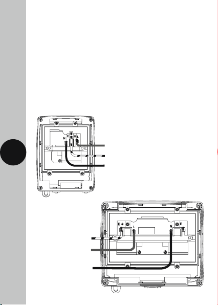
5.1 TGV101N, TGV201N & TGV103N Wiring Diagrams
Figure 7
TGV101N
230V 50Hz AC Mains Supply
9
Earth
230V 50Hz AC
Mains Supply
Mains Neutral Supply
Figure 8
TGV201N
Earth
Mains Neutral Supply
Page 11
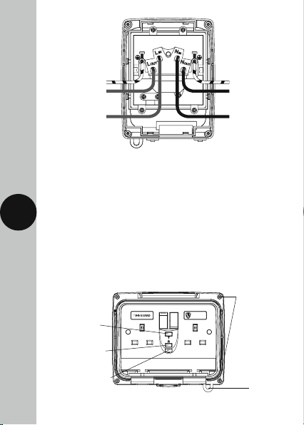
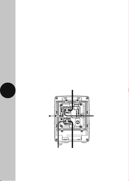
Figure 9
TGV103N
Earth Earth
Live
Supply Out
230V 50Hz AC
Mains Supply
6. TGV104N, TGV204N, TGV205N
Installation
1. IMPORTANT Switch off the electricity at the fuse box by removing
10
the relevant fuse or switching off the circuit breaker before
proceeding with the installation.
2. Using a Philips screwdriver, separate the faceplate from the back
box by removing the four tapped screws located in each corner.
See figure 10 & 11 for your chosen product
Test button (T)
Reset button (R)
Red flag indicator
(shown when
current is live)
Am03 evitcA
NO – galF deR
esU erofeB )T( tseT
Neutral
Supply Out
Mains Neutral
Supply
Tapped screws
Figure 10
TGV204N &
TGV205N
Front Plate
Lid clip for
padlocks
Page 12
Red flag indicator
(shown when
current is live)
Reset button (R)
3. Using the back plate as a template mark the position for the
holes. Note the back plate must be mounted in the correct
orientation, following the ‘TOP’ marking inside the back plate.
30mA 1 n DP
FlagaboveResetR
Red:ON Black:OFF
ALWAYS TEST
BEFORE USE
Press Test T, flag
should disappear.
If not, do not use.
Reset after testing
RCD16ML
F
U
S
E
If the mounting position desired is uneven use a sheet of
11
marine ply as a base plate and fit the back box.
4. Drill the wall using a 4mm Ø drill bit making sure not to infringe
or compromise any gas, water pipes or cables. Insert the rawl
plugs into the holes.
5. The drain feature must be drilled out using a 5mm drill if the top
or side entry conduit is used. Opening this drain hole will reduce
the IP rating of the product. Remember – open out the lower
drain feature only.
6. Select the required entry point by unscrewing the appropriate seal
located on all four sides of the back box. If conduit is not going
to be used, a waterproof cable with suitable IP rated 20mm cable
glands will be required to maintain the overall IP rating. If the
bottom entry conduit is used, there must be adequate drainage
from the lowest point of the conduit.
7. Follow suit using the same method depicted in stage 6 to create
an exit point for the output supply cable to follow through on.
Test button (T)
Figure 11
TGV104N
Front Plate
Tapped screws
Lid clip for
padlocks
Page 13
8. Secure the back box to the wall using suitable screws for the rawl
plugs installed. Ensure that the back box is correctly orientated
following the ‘TOP’ marking which is labelled inside.
9. Pass though the 230V AC 50Hz mains supply cable and secure
the cables tightly to their respective terminals ensuring that all
bare conductors are sleeved and that correct polarity is observed,
see figure 12 and 13 for the appropriate wiring diagram for your
chosen product. Note that if metal conduit is being used the earth
continuity between the conduits must be maintained.
10. Once the mains supply is connected to the correct terminals,
mount the face plate over the back box aligning the four screws
from the face plate to the four mounting holes on the back box.
Tighten until secured.
6.1 TGV104N, TGV204N, TGV205N Wiring Diagrams
Figure 12
TGV104N
12 13
Neutral Supply to Load
Earth
230V 50Hz AC Mains Supply Mains Neutral Supply
Live Supply
to Load
Page 14
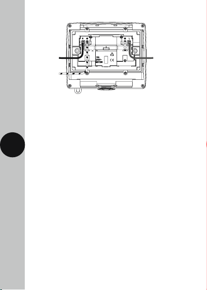
Figure 13
TGV204N
Mains
Neutral
Supply
Earth
This diagram
applies to both
TGV204N &
TGV205N
230V 50Hz AC
Mains Supply
6.2 TGV104N, TGV204N and TGV205N Testing & Usage
To test: Ensure supply is connected
RESET – press the grey (blue for TGV205N) button marked
Reset (R), the status indicator should show red.
Test – press the red button marked Test (T), the status indicator
13 14
should show black. This indicates that the RCD has been tripped
and power has been disconnected from the outlet.
RESET – press the grey (blue for TGV205N) button marked
reset (R) again; the status indicator should show red.
If all the above operations work satisfactory, the RCD is safe for use.
If this test procedure is not completed to a satisfactory standard,
do not use the RCD and seek professional advice.
In applications such as hand driers it may not be practical to expect
each user to test before use. In this case we suggest an appropriate
person applies the test routine twice a day.
After satisfactory testing the RCD, any connected appliance may
be switched on, and used in the confidence that the user is protected
from electric shock by rapid disconnection of the supply.
Page 15

3 Year Guarantee
In the unlikely event of this product becoming faulty due to defective
material or manufacture within 3 years of the date of purchase,
please return it to your supplier in the first year with proof of
purchase and it will be replaced free of charge. For the second
and third years or any difficulty in the first year telephone the
helpline on 020 8450 0515.
Note: A proof of purchase is required in all cases. For all eligible
replacements (where agreed by Timeguard) the customer is
responsible for all shipping/postage charges outside of the UK.
All shipping costs are to be paid in advance before a replacement
is sent out.
14
Page 16

If you experience problems, do not immediately
return the unit to the store.
Telephone the Timeguard Customer Helpline;
HELPLINE
020 8450 0515
or email helpline@timeguard.com
Qualified Customer Support Co-ordinators will be on-line
to assist in resolving your query.
For a product brochure please contact:
Timeguard Limited.
Victory Park, 400 Edgware Road,
London NW2 6ND
Sales Office: 020 8452 1112
or email csc@timeguard.com
www.timeguard.com
67.058.516 (Issue 2)
Zerofour – November 2016
 Loading...