

Timeguard SupplyMASTER FST11A, SupplyMASTER FST17A Installation & Operating Instructions Manual
FUSED SPUR
Cat No. FST1
7
TIMESWITCH
INSTALLATION & OPERATING
Cat No. FST11A - 24 Hour
Cat No. FST17A - 7 Day
Installation & Operating
Instructions
INSTRUCTIONS
1. General Information
F
U
S
E
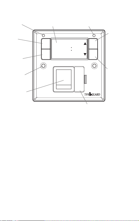
Power
ON LED
Sets
programmes
Sets date
and time
Fixing hole
Double pole
switch
Display (back lit for 30 secs
when any button is pressed)
TimeDayMonthYear
Prog Adv
Prog
ON
OFF
8
HOLDHOLD
Time Bst
MODE BOOST 12
Mo Tu We Th Fr Sa Su
FST-17A
Reset button
(recessed)
SET
8888
Override until
next programme
change and
increments
displayed value
during time and
programme
setting
Boost for 1 or 2
hours and
decrements
displayed value
during time and
programme
setting
BS 1362 (1"x
1
/4") fuse
Fig. 1
FST17A / FST11A Front Panel
Contents:
1 Supplymaster.
2 3.5mm screws.
1 Bag containing: 2 screws, cable blank and cable clamp.
1 Instruction leaflet.
The FST11A (24 hour) and FST17A (7 day) are units which mount onto a
BS 4662 flush mount single box, or a BS 5733 surface mount single box (25mm deep
in either case). There is provision for a single front exit output cable, with in-built
cable clamp.
The unit combines the facilities of a time switch and a double pole switched, fused
connection unit capable of being wired directly into a ring main. The contacts are not
volt free, and there is no provision for a permanent ON, or for earth continuity (for
which the back box termination can be used if required). The unit has automatic
daylight saving pre-programmed in.
2. Battery
L OU T
N IN
L IN
N OU T
The unit has an in-built non replaceable, rechargeable battery, which will keep the
programmed times during power down situations for up to 4 weeks. If the main
switch is left in the OFF position for longer than this, the display will go blank. If the
screen goes blank, once power is restored and 4 hours elapsed (to give a working
battery charge) reset must be pressed, and times / programmes re-entered.
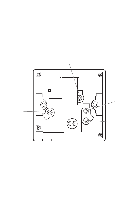
Switched live terminal
(load live connection)
230 V~
13A
Supply live
terminal
T40
Supply neutral
terminal
Switched
neutral terminal
(load neutral
connection)
Fig. 2
FST17A / FST11A Rear Connections
3. Applications
Energy consuming appliances such as immersion heaters and storage heaters up to
13A total loading can be supplied by the FST11A / FST17A enabling users to make
use of economy 7.
If the user has other appliances which do not have a push button start such as
washing machines, dishwashers and tumble dryers these may also be controlled in
the same way. It can also be used to control lighting, if a neutral is made available.
Lighting up to 2.5kw filament, or 500W fluorescent can also be controlled.
4. Installation
O
P
The unit is designed to replace an existing single gang connection unit or fixed
appliance outlet giving timed mains output, protected by a BS 1362 fuse. The unit is
capable of forming part of a ring main (the terminals can accept 2 x 2.5mm sq.
cables) or terminating a spur off the ring main. The unit requires a minimum depth of
25mm within the box.
Ensure that the wiring is adequate for the load to be carried. Connect incoming and
outgoing cables to the relevant terminals. Secure the unit to the back box with the
3.5mm screws provided forming the cables during installation to avoid entrapment
and cable damage.
Use the earth terminal in the back box for earth continuity if required. If installed into
a metal back box, earthing of the back box is required.
There is a removable cable blank to cover the front cable exit if this feature is not
required. If front exiting cable is required, for instance to connect to a washing
machine, use the cable clamp supplied to secure the outgoing cable.
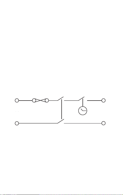
BS 1362
L IN L OUT
SUPPLY
SUPPLY AP
N IN
N IN
fuse
Double pole switch
Fig. 3
Internal Schematic of FST17A / FST11A
5. Fuse
Use the appropriate BS 1362 fuse for the load. The unit is supplied with a
suitable 13A fuse.
Time switch
L OUT
APPLIANCE
N OUT
N
 Loading...