

Page 1

360º SURFACE MOUNT
CEILING PIR LIGHT
CONTROLLER
Cat No. SLW360
INSTALLATION & OPERATING
INSTRUCTIONS
Page 2
Introduction
The SLW360 utilises passive infrared technology to
detect heat radiation of moving human bodies.Upon
detection, the attached lighting load will illuminate for
a user-determined time period. An integral daylight
sensor ensures day or night-only operation.
Important Information: Light Pollution and
considerate Lighting
Please be aware of the annoyance over-lighting an area
can cause to your immediate neighbours. Light
pollution caused by incorrectly installing a unit or
over-lighting an area can be limited by carefully
considering the location and position of your unit
before installation. The light spread on all halogen
floodlights can be reduced by angling the floodlight
downwards on the mounting bracket. This will also
concentrate the light on your property and limit the
potential inconvenience of the light shining into your
neighbours windows etc.
Please see Selecting a Location for information on
1
choosing the optimum location for any security light
controlled by this unit.
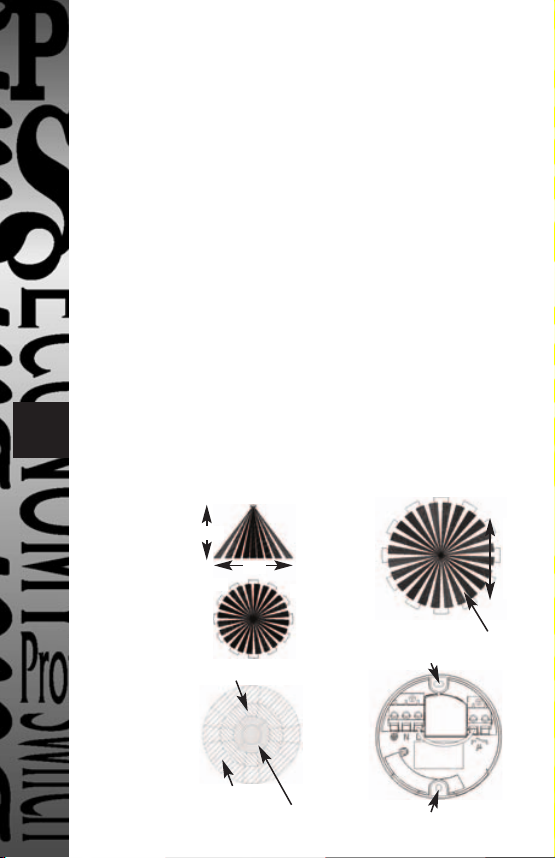
Side View
A
2.5m
B
Side View
C
Lens Mask
Restrict long detection
Restrict detection directly under sensor
6m
Restrict short detection
360º
Mounting hole
D
Mounting hole
More sensitive
Less sensitive
Page 3
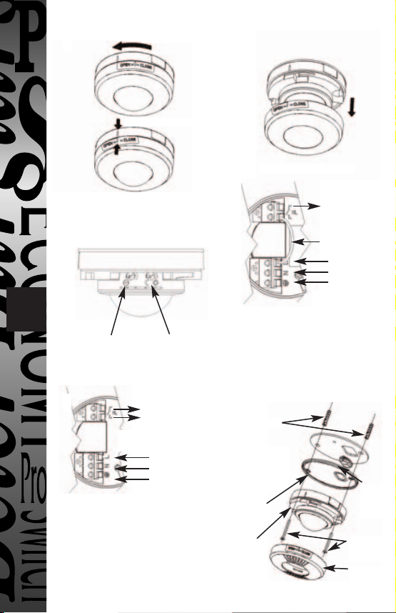
E
Twist cover anti-clock wise
Align marks on moulding
Remove decorative cover
2
F
Time On
setting
H
Factory fitted
bridge wire REMOVED
In the above illustration:
- the L1 L2 terminals are used to control a DC
load or if the load uses a different phase or
voltage supply from the AC mains in.
- factory fitted bridge must be removed to
isolate L1 & L2 terminals from AC mains in.
Lux -
Dusk/Dawn
setting
Switched
L1
Load
L2
OUT
L
N
E
Mains Supply IN
G
In the above illustration:
- 4 core cable may be used
- there is no external junction box
- A bridge is provided, prewired to bridge
across live supply from AC mains to the
output load
Ceiling mount assembly method.
I
Wall plugs x 2.
Sponge gasket.
Fit if mounting
the unit outdoors.
Discard if fitting
indoors
Mounting
Plate
Sensor
Switched
Load
L1
OUT
Factory fitted
bridge wire
L
N
E
Mains Supply IN
Mounting
screws
Top cover
Cable
gasket
Page 4

3
Parts included
• PIR Sensor unit.
• Instruction manual. Please keep safe for future
reference.
• Accessory Pack. Includes 2 x wall plugs, 2 x wall
fixing screws, 1 x lens mask sticker.
• 1 x outdoor mounting sealing gasket.
• 1 x incoming/outgoing wire gasket.
Tools and parts needed
• 3 core flexible cable.
• Electric/hand-held drill & bits.
• Terminal or Electricians screwdriver.
• Large slotted/philips screwdriver.
• Wire cutters suitable mains interconnect cable.
This product is suitable for indoor or outdoor use.
Connected load must not exceed maximum
2000W filament/incandescent or 500W fluorescent/low
energy lighting.
Do not attempt to install during wet weather, if you are
suffering from nausea or dizzy spells or on medication
with similar side effects. If in any doubt, consult a
qualified electrician.
Not suitable for use with discharge lighting.
Selecting a location
The motion detector has a number of detection zones,
at various vertical and horizontal angles as shown (see
diagram A).
A moving human body needs to cross/enter one of
these zones to activate the sensor. The best all-round
coverage is achieved with the unit mounted at the
optimum height of 2.5m.
Careful positioning of the sensor will be required to
ensure optimum performance. See diagram A detailing
detection range and direction.
Page 5

4
The sensor is more sensitive to movement ACROSS its
field of vision than to movement directly TOWARDS
(see diagram B). Therefore position the unit so that the
sensor looks ACROSS the likely approach path.
Avoid positioning the sensor where there are any
sources of heat in the detection area (extractor fans,
tumble dryer exhausts etc.) including opposite any
other light sources such as other security lights.
Reflective surfaces (ie pools of water or white-painted
walls) and overhanging branches may cause false
activation under extreme conditions.
During extreme weather conditions the motion sensor
may exhibit unusual behaviour. This does not indicate
a fault with the sensor. Once normal weather conditions
return, the sensor will resume normal operation.
Installation
IMPORTANT
Switch off the electricity at the fuse box by removing the
relevant fuse or switching off
the circuit breaker before proceeding with the installation.
All fittings should be installed by competent person in
accordance with IEE Wiring Regulations (BS7671)
After choosing a suitable location (see previous section)
install the unit as follows:
The unit is suitable for connection to a 230 V ac 50Hz
electricity supply. It is suggested that 3-core round
flexible cable of 1 sq. mm gauge is used. An internal
switch should be installed to switch the power to the
unit ON & OFF. This allows the sensor to be easily
switched off when not required or for maintenance
purposes.
Remove the top cover of the sensor by twisting the top
cover anticlockwise until the arrows shown on diagram
E are aligned.The top cover can now be removed from
the sensor body.
Mark the position of the fitting holes. See diagram G.
Drill the holes. Insert the rawl plugs into the holes.
Page 6

5
PIERCE & PASS THE INCOMING AND OUTGOING
CABLE THROUGH THE GROMMET BEFORE
SECURING CEILING MOUNTING PLATE TO
CEILING.
It is recommended that the grommet is pierced with a
screwdriver to ensure a better seal.
Connection
THERE ARE 2 POSSIBLE CONNECTION SCENARIOS
1. Standard connection. See Diagram G.
The factory fitted “bridge” wire must not be removed.
Connect the 4 core mains supply cable to the terminal
block on the unit as follows:-
NEUTRAL (Blue) N
EARTH (Green/Yellow)
LIVE (Brown) L
Connect the fourth core cable or incoming cable from
the lighting load to the L1 terminal block on the unit as
follows (see connection diagram G)
SWITCHED LIVE L1
2. Switching DC loads or loads which use a different
phase or voltage supply from the AC mains. See
Diagram H. Remove the factory fitted bridge wire.
Connect the 3 core mains supply cable to the terminal
block on the unit as follows:-
NEUTRAL (Blue) N
EARTH (Green/Yellow)
LIVE (Brown) L
Connect the load in series with the load supply
between L1 and L2 terminals.
Please note that the function of L1 and L2 can viewed
as a simple switch controlled by the PIR sensor
electronics.
When wiring is complete, it is recommended that the
ceiling mounting plate is fitted to the sensor
body and fixed to the ceiling as follows:-
Page 7

6
See diagram “I” for ceiling mounting assembly method.
Fit the sensor assembly to the ceiling, if mounting
outdoors, it is essential that the sponge gasket is placed
between the ceiling mounting plate and the sensor
itself to ensure a good seal is maintained.
If mounting the unit indoors, the gasket is not required
and can be discarded.
Insert fixing screws through the sensor assembly into
the wall plugs and secure.
Do not overtighten, if using a power screwdriver
ensure it is set to a low torque setting so as not to
damage the unit.
Set the unit up as follows, before refitting the
decorative cover.
Setting up
Walk Test Procedure
Set the two adjustment controls on the underside of the
unit (diagram C) to the following positions:
TIME - Fully anti-clockwise
DUSK - Fully clockwise
The unit will now operate during daytime as well as at
night, illuminating the lamp for approx. 5 seconds each
time. This allows testing to be carried out to establish the
best position for the sensor.
The lamp will immediately illuminate as the unit goes
through its "warm-up" period. After approximately 1 - 2
minutes the lamp will extinguish. Try to remain outside
the detection area during the warm-up period.
Walk around the sensor to establish the detection area.
The sensor will detect within an approximately six metre
diameter circle from the centre of the sensor location.
As you cross a detection "zone" the lamp will illuminate.
Now stand still until the lamp extinguishes (this should
take approx. 5 seconds).
Page 8

7
Start moving again. As you cross each "zone" the lamp
will illuminate.
Repeat the above, walking at various distances and
angles to the unit. This will help you to establish the
detection pattern.
Masking the Sensor Lens
To reduce the sensor coverage, preventing detection in
unwanted areas, mask the sensor lens using the lens
mask sticker supplied (see diagram D). For your
information, the centre section of the lens covers short
range detection, and the outer edge of the lens covers
long range. Mask the sensor to suit your installation.
Setting Up for Automatic Operation
When walk tests are complete, the unit can be adjusted
for automatic operation :
The TIME setting controls how long the unit remains
illuminated following activation & after all motion
ceases. The minimum time (fully anti-clockwise) is
approx. 5 seconds, whilst the maximum time (fully
clockwise) is approx. 18 minutes. Set the control to the
desired setting between these limits.
The DUSK control determines the level of darkness
required for the unit to start operating. The setting is
best achieved by the procedure below:
Set the DUSK control knob fully anti-clockwise. The
unit will now start operating at dusk.
If you require the light to activate earlier, wait until the
ambient light level reaches the level of darkness at
which you wish the lamp to become operative,
SLOWLY (a small step at a time) rotate the control in a
clockwise direction until a point is reached where the
lamp illuminates. Leave the control set at this point.
Page 9

8
At this position, the unit should become operative at
approximately the same level of darkness each evening.
Observe the operation of the unit. If the unit is starting
to operate too early (ie. when it is quite light), adjust
the control slightly anti-clockwise. If the unit starts to
operate too late (ie. dusk), adjust the control slightly
clockwise.
Continue to adjust until the unit operates as desired.
Once the unit is set up as desired, refit the top cover by
aligning the arrows shown on diagram E and twisting
clockwise until cover is secure.
Manual Override Mode
The light can be switched on for longer time periods by
use of the Manual Override Mode. This can be
activated at night by using the internal wall switch or
circuit breaker.
Switch the internal wall switch twice (off/on, off/on)
within 2 seconds. The unit will now illuminate
continuously until dawn or until it is switched back
into Detection Mode.
To return to Detection Mode switch the internal wall
switch off and then back on again within 1 second.
Page 10

Troubleshooting guide
Problem
• Lamp stays
ON all the
time at
night.
• PIR keeps
activating
for no reason
(at random).
• PIR sensor
will not
operate at
all.
9 1
• The PIR
sensor will
not operate
at night.
• Unit activates
during the
daytime
Solution
Cover PIR lens with a thick cloth. If the
light turns out, check detection area for
heat or reflective source.
If the light stays on, check wiring. See
Section 3.
Turn off at the internal wall switch. Leave
for 30 seconds and turn on again. Leave for
at least 18 minutes. If light activates, check
area for false activation from heat, wind or
reflective source.
Check that the power is switched ON at the
power supply or internal wall switch.
Turn OFF the power to the unit and check
the wiring connections.
Check the lamp. If the lamp has failed,
replace. Ensure that the lamp is seated
correctly in the lampholder. Please note
that the unit will not detect through glass.
(e.g. in a glazed porch).
The level of ambient light in the area may
be too bright to allow operation at the
current DUSK setting. During the hours of
darkness, adjust the DUSK control slowly
clockwise until the lamp illuminates. Refer
to previous section for more details.
Adjust the DUSK Control setting anticlockwise to lower the level of ambient
light required for activation.
• PIR
coverage is
poor/
sporadic
Unit may be poorly located. See previous
section - ‘Selecting A Location’ and
re-locate the unit.
Page 11

10
Problem
• Detection
range varies
from day to
day
Solution
PIR detectors are influenced by climatic
conditions. The colder the ambient
temperature, the more effective the sensor
will be. You may need to make seasonal
adjustments to the detector head position to
ensure trouble-free operation all year
round.
Technical specifications
Detection Range:
Detection Angle:
Power Supply:
Maximum Switchable Load:
Time On Adjustment:
Dusk Level Adjustment:
Environmental Protection:
Conforms to Directives:
Up to 6 metres diameter
(3m Radius) at mounting
height of 2.5m
360º
230 V AC ~ 50Hz
2000W (e.g.20 x 100W GLS)
Incandescent/filament or
500W Fluorescent/low energy
lighting
Not suitable for discharge
lighting.
75W Fan
5 seconds - 18 minutes
Day & night or night only
operation
IP44 (suitable for outdoor use)
73/23/EEC and 89/336/EEC
Page 12

3 Year Guarantee
THREE YEAR
GUARANTEE
3
In the unlikely event of this product becoming faulty due to
defective material or manufacture within 3 years of the date
of purchase, please return it to your supplier in the first year
with proof of purchase and it will be replaced free of charge.
For the second and third years or any difficulty in the first
year telephone the helpline on 020 8450 0515.
HELPLINE
020-8450-0515
For a product brochure please contact:
Victory Park, 400 Edgware Road,
or email csc@timeguard.com
Timeguard Ltd.
London NW2 6ND
020-8452-1112
 Loading...