

Page 1
2300W PIR Light Controller
c/w RF Control
Model: SLB2300RF – Black
Model: SLW2300RF – White
Model: LEDPROFOB RF Remote Fob
Installation & Operating Instructions
Page 2

1. General Information
These instructions should be read carefully
and retained for further reference and maintenance.
2. Safety
• Before installation or maintenance, ensure the
mains supply to the PIR sensor is switched off
and the circuit supply fuses are removed or the
circuit breaker turned off.
• It is recommended that a qualified electrician is
consulted or used for the installation of this PIR
sensor and install in accordance with the current
1
IEE wiring and Building Regulations.
• Check that the total load on the circuit including
when this PIR sensor is fitted does not exceed the
rating of the circuit cable, fuse or circuit breaker.
3. Technical Specifications
PIR Light Controller
• Operating Voltage: 230V AC 50 Hz
• This product is of Class ll Construction and must
not be earthed
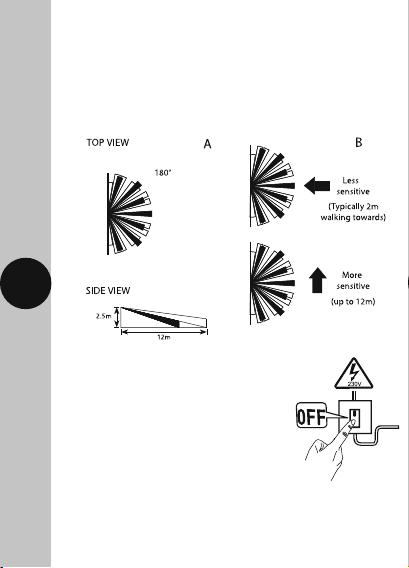
• Detection Angle: 180°
• Motion Detection Range:
Up to 12m distance at a 2.5m mounting height
Page 3

• Back plate Mounting Centres: 51mm
• Maximum Switching Load;
2300W Halogen lighting
500W Fluorescent tube w/o PF correction
250W LED lighting (PF > 0.9)
200W CFL Lighting
• Time ON Adjustment: 3 seconds to 18 minutes
• Warm Up Period: Approximately 35 seconds
• Dusk (LUX) level adjustment: 2 to 1000 Lux
• Operating Temperature: -20°C to +40°C
• Standby (W): <0.5W
• Manual Override Mode: ON/OFF operation using
RF Remote Fob (6 fobs max)
• Sensor Head Adjustment: Pan angle = Left/right
2
90°, Tilt angle = Up 15°, Down 60°
• RF Module: RX Receiver
• RF Frequency: 433.92MHz
• IP55 Rated suitable for restricted external
applications
• CE Compliant
• Dimensions (H x W x D): 96 x 78 x 158mm
• Multiple PIR light controller switching: A maximum
of 8 SLB-W2300RF PIR light controllers can be wired
in parallel, to enable any detector to turn ON all the
lights connected. The total load must not exceed
the lamp rating of a single SLB-W2300RF unit.
Page 4

RF Remote Fob
• Battery: 3V (1x CR2032)
• Battery Life:
Approximately 24 months (@ 10x opt/day)
• Class Rating: Class III
• Transmission and Receiving Distance:
100m hand held (clear line of sight)
10m when mounted inside a wall switch
(recommended mounting height = 1.2m)
• Total number of fobs usable per PIR: 6
• Operating Temperature: -20°C to +40°C
• RF Module: TX Transmitter
• RF Frequency: 433.72MHz to 434.12MHz
• IP44 Rated suitable for restricted external
3
applications
• CE Compliant
• Dimensions (H x W x D): 60 x 38 x 15mm
4. Pack contents
• 1x SLB-W2300RF PIR Light Controller
• 1x LEDPROFOB RF Remote Fob
• 1x Instruction Manual
• 1x 3V CR2032 Battery
• 1x Lens Sticker
• 2x Fixing Screws
• 2x Wall Plugs
• 2x Wire (for wall mounting a fob)
Page 5

5. Selecting a Location
• The light controller has number of detection zones,
at various vertical and horizontal angles as shown
(see diagram A).
• A moving human body needs to cross/enter one
of these zones to activate the light controller.
The best all-round coverage is achieved with the
unit mounted at the optimum height of 2.5 metres.
• Careful positioning of the light controller will be
required to ensure optimum performance (see
diagram A detailing detection range and direction).
• The light controller is more sensitive to movement
4
ACROSS its field of vision than to movement
directly TOWARDS (see diagram B). Therefore
position the unit so that the light controller looks
ACROSS the likely approach path.
• Avoid positioning the light controller where
there are any sources of heat in the detection
area (extractor fans, tumble dryer exhausts etc.)
including opposite any other light sources such
as other security lights.
• Reflective surfaces (i.e. pools of water or white
painted walls) and overhanging branches may
cause false activation under extreme conditions.
Page 6
• During extreme weather conditions the motion
light controller may exhibit unusual behaviour.
This does not indicate a fault with the light
controller. Once normal weather conditions return,
the light controller will resume normal operation.
5
6. Installation
6.1 Ensure the mains supply is
switched off and the circuit
supply fuses are removed or
the circuit breaker turned off.
6.2 An isolating switch should be installed
to enable the power to be switched ON & OFF
for maintenance purposes.
Page 7

6.3 Remove the back plate from the PIR light controller.
6.4 Mark the position of the mounting holes on the
wall using the back box as a template.
6
6.5 Drill the holes ensuring not to infringe with any
gas/water pipes or electrical cables that may be
hidden below the surface. Insert the rawl plugs
into the holes.
6.6 Pass the 230V 50Hz mains supply and load
cables through the cable entry point on the
backing plate, ensuring the grommet(s) is used to
maintain the IP rating of the PIR light controller.
Page 8

6.7 Fix the back plate to the wall. Take care not to
overtighten the screws to prevent damage to the
back plate. If using a power screwdriver, use the
lowest torque setting.
6.8 Terminate the cables into the terminal block
7
ensuring correct polarity is observed and that
all bare conductors are sleeved (See section 6.
Connection Diagram).
6.9 Re-attach the PIR light controller to the back
plate pushing firmly into place.
Page 9

7. Connection Diagram
• Connect the cables to the terminal block as follows;
230V AC 50Hz
MAINS SUPPLY
N
L
8
230V 50Hz Mains Supply
Live Supply (Brown or Red) to L
Neutral Supply (Blue or Black) to N
A ‘Loop Terminal’ (centre terminal) is provided
should a 3 core cable be used
Load
Switch Live (Brown or Red) to L
Neutral Load (Blue or Black) to N
ISOLATION
SWITCH
LOOP
TERMINAL
l
LN
L
LOAD
1
Page 10

8. Setting Up
Walk Test Procedure (Test Mode)
• The sensor will rotate from left to right, and will
tilt downwards. Adjust the light controller to point
in the required direction and angle down to limit
forward range as required.
• Set the two adjustment controls on the underside
9
of the unit to the following positions:
DELAY TIME ADJUST – Fully anti-clockwise
DUSK LEVEL ADJUST – Fully clockwise
• Turn the power to the unit ON.
Page 11

• The lamp will illuminate for approximately 35
seconds. This indicates the unit is wired correctly.
The unit is in Test Mode when the light turns OFF.
• If the detection area is too small for you
requirements, try angling the PIR light controller
head up. This will increase the detection area.
Angling the head downwards will reduce the
detection area should a smaller coverage be
required.
Setting Up for Automatic Operation
(Auto Mode)
• When walk tests are complete, the unit can be set
10
into Auto Mode.
• The DELAY TIME ADJUST setting controls how long
the unit remains illuminated following activation
and after all motion ceases.
• The minimum time (fully anti-clockwise) is approx.
3 seconds, whilst the maximum time (fully
clockwise) is approximately 18 minutes.
• Set the control to the desired setting between
these limits.
• The DUSK LEVEL ADJUST control determines the
level of darkness required for the unit to start
operating. The DUSK adjustment knob is indicated
by the ‘Moon’ and ‘Sun’ symbols).
Page 12

• Set the light threshold to maximum (fully clockwise/
Sun end), then turn the control anti-clockwise
about three quarters of the way round to the
Moon end. This will give operation after DUSK
approximately.
• For a more accurate setting of the DUSK LEVEL
ADJUST control turn it fully anti-clockwise (Moon
end) and leave for at least 20 seconds for the unit
to settle.
• When the ambient light level reaches that required
for DUSK, adjust the DUSK control a small amount
clockwise pausing to try to get the unit to detect
and turn the lights under control ON by moving a
11
hand slowly backwards and forwards across the
front of the detector lens for around 5 seconds.
• Continue to turn the control small amounts in a
clockwise direction, stopping after each adjustment
to try to get the unit to detect as above.
• Eventually detection will occur and the DUSK level
is now set as required.
9. Masking the PIR Light
Controller Lens
• To reduce the PIR light controllers coverage,
preventing detection in unwanted areas, mask the PIR
light controllers lens using the lens sticker supplied.
Page 13

• The top section of the lens covers long range
detection, the bottom covers short range.
Similarly the left and right lens sections cover
the left and right detection area respectively.
• Mask the PIR Light controllers lens to suit
your installation.
10. Accessing Terminals
12
After Installation
This may be necessary to add further lighting for instance
and the following procedure for removing the unit from
its back plate should be followed:-
10.1 Insert a flat blade screwdriver in the catch at the
sides of the unit and lever it outwards.
Page 14

10.2 The terminals are now accessible. If adding
lighting, ensure the unit’s maximum switching load
rating is not exceeded (see section 3. Technical
Specifications).
10.3 Re-attach the PIR light controller to the back plate
pushing firmly into place.
11. RF Remote Fob
Battery
• To access the battery holder,
remove the back plate from
the fob as shown in
the diagram.
Pairing the RF Remote Fob(s) with the PIR
13
Light Controller
Note: You must complete the Walk Test Procedure
before you can pair the devices. The pairing of the
fob(s) cannot be actioned with the PIR light controller
set to Test Mode. Make sure the PIR light controller is
functioning correctly and set for Automatic Operation
(Auto Mode) before you continue.
• Press the centre button that
is located on the bottom
of the PIR light controller once
(do not press and hold for
longer than 4 seconds), the
lamp will flash twice to indicate
it is ready to pair your fob(s).
Page 15

Note: once the lamp has flashed twice, the PIR
sensor will no longer trigger the lamp with motion
until the pairing sequence has been completed.
• Press the fob button once.
The lamp will turn ON
for 3 seconds, and back
OFF again, to indicate
it has been registered.
Note: If you have more than one fob to pair
(Up to 6 max) then press the fob buttons, one at a
time, waiting for the lamp to turn ON for 3 seconds
and back OFF again each time, between presses.
You cannot pair a 7th fob. If attempted, the lamp
will flash twice to indicate it has not been paired.
• After the last fob press, wait for approximately
14
30 seconds until the lamp flashes twice.
This will indicate that your fob(s) have successfully
been paired.
Note: once the lamp has flashed twice, the PIR
light controller will begin to trigger with motion
once again.
• Test your fob(s) by pressing the fob button once to
turn the lamp ON, and once to turn the lamp OFF. If
you are using more than fobs, you are able to turn
the lamp ON using one fob, and turn the lamp OFF
using another.
Page 16

Erase all RF Remote Fobs from the PIR
Light Controller
• Press and hold the centre button, located on the
bottom of the PIR light controller, for approximately
5 seconds. The lamp will flash 5 times.
This indicates that un-pairing has been successful.
Installing a RF Remote Fob into a Wall Switch
• Remove the rubber caps from
the bottom of the fob as shown.
15
• Using 2 of the wires supplied,
push them firmly into the
2 spring clamp terminals.
Check they are both secure
with a light tug.
Remove
rubber caps
Page 17

• Follow the wall
switch wiring
image for
connection.
Dry Contact
w/o 230V AC Potential
12. Troubleshooting Guide
16
PROBLEM
• Lamp stays
ON all the time
night and day.
• Lamp stays
ON all the
time at night,
or PIR keeps
activating at
random for
no apparent
reason
SOLUTION
Check wiring connections.
Wires to L and L’ terminals may
be transposed.
The unit may be suffering from false
activation. Cover the sensor lens completely
with black PVC tape. This will prevent the
sensor from ‘seeing’ anything. If the unit
now switches off after the set time duration
and does not re-activate, this indicated that
the problem was caused by false activation.
The problem may be solved by slightly
adjusting the direction/angle of the sensor
head (see previous section). If however, the
unit continues to remain ON or to operate
randomly then the unit is faulty and should
be replaced.
Page 18

17
• PIR sensor
will not operate
at all.
• The PIR sensor
will not operate
at night.
• Unit activates
during the
daytime.
You may not be allowing the unit time to
complete its warm-up period. Stand well out
of the detection range and wait (the warmup period should never exceed 5 minutes).
Occasionally, winds may activate the sensor.
Sometimes passages between buildings
etc. can cause a “wind tunnel” effect.
Ensure the unit is not positioned so as to
allow detection of cars/people using public
thoroughfares adjacent to your property.
Ensure that the unit is mounted securely,
even the slightest movement can result
in a false detection.
Check that the power is switched ON at the
circuit breaker/internal wall switch.
Turn OFF the power to the unit and check
the wiring connections as per the diagram
(see 7. Connection Diagram).
Ensure no connections are loose.
Check the bulb (if it’s replaceable). If the
bulb has failed, replace (do not hold the
bulb directly with fingers, use a tissue or
clean dry cloth).
Where relevant, ensure the bulb is seated
correctly in the bulb holder.
Refer to section 8. Setting Up for DUSK
control adjustment.
Refer to section 8. Setting Up for DUSK
control adjustment.
Page 19

• PIR coverage is
poor/ sporadic.
• Detection range
varies from day
to day.
Unit may be poorly located. See Section
5. Selecting a Location and re-locate
the unit.
PIR sensors are influenced by climatic
conditions. The colder the ambient
temperature, the more effective the sensor
will be. You may need to make seasonal
adjustments to the sensor head position
to ensure trouble-free operation all year
round.
3 Year Guarantee
In the unlikely event of this product becoming faulty due to
defective material or manufacture within 3 years of the date
of purchase, please return it to your supplier in the first year
with proof of purchase and it will be replaced free of charge.
For the second and third years or any difficulty in the first year
18
telephone the helpline on 020 8450 0515.
Note: A proof of purchase is required in all cases. For all eligible
replacements (where agreed by Timeguard) the customer is
responsible for all shipping/postage charges outside of the
UK. All shipping costs are to be paid in advance before a
replacement is sent out.
Page 20

If you experience problems, do not immediately
return the unit to the store.
Telephone the Timeguard Customer Helpline;
HELPLINE
020 8450 0515
or email helpline@timeguard.com
Qualified Customer Support Co-ordinators will be on-line
to assist in resolving your query.
For a product brochure please contact:
Timeguard Limited.
Victory Park, 400 Edgware Road,
London NW2 6ND
Sales Office: 020 8452 1112
or email csc@timeguard.com
www.timeguard.com
67.058.620 (Issue 1)
Zerofour – May 2018
 Loading...