

Page 1

Round Pattern 24 Hour
Electromechanical
Time Controllers with
Half Day & Day Omit
Cat Nos. RTS113/RTS113Q/RTS114/RTS114Q
Installation & Operating Instructions
Page 2
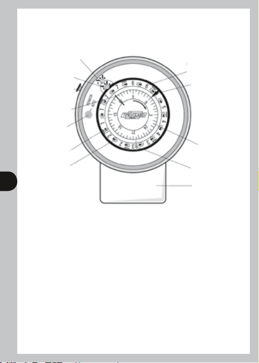
RTS113/RTS113Q/RTS114/RTS114Q
Round Pattern Electromechanical Timeswitches
7 day control (blue)
24 hour control
(Red)
Permanent ON
override
push button
Time marker
Permanent
override
indicator
AM segment
PM segment
1 2
7 day programming
ring (divided into
12 hour steps)
Blue tappet (OFF)
24 hour
programme
Red tappet (ON)
Terminal cover
ring
1.0 Description:
1.1 Application
The RTS113/RTS113Q/RTS114/RTS114Q round pattern electromechanical, double insulated time
controllers come with a 3 or 4 pin plug-in wirable base. They are compatible with the bases used
for the single channel ON/OFF mains linked and voltage free industry standard round pattern
timeswitches. Consequently the RTS113/RTS113Q/RTS114/RTS114Q can be considered as plug-in
service replacements for these units as well as for new installations.
1.2 Features
The timeswitch comes in four forms all driven by quartz controlled stepping motors –
with mains linked contacts, the RTS113 and the RTS113Q with battery back-up and with voltage
free contacts, the RTS114 and the RTS114Q with battery back up.
• Override to next programme change (daily programme only).
• Permanent ON facility.
• RTS113Q/RTS114Q only – battery power reserve continuously charged while the unit
is connected to mains.
• Daily operation with half day(s) and day(s) omit.
Page 3
1.3 Technical Data
Type: RTS113/RTS113Q/RTS114/RTS114Q
Type of programme: Daily with half day(s) and day(s) omitted
over a 7 day period if required
Operating voltage: 220-240V AC 50Hz
*Switching capacity: 20A, 240V~ for resistive loads
Contact material: Hard silver
Type of contact: ON/OFF mains linked RTS113/RTS113Q,
voltage free RTS114/RTS114Q
Time base: Quartz
Operating accuracy: ≤ ± 1 sec./day at 23°C
Min. switching interval: 30 min, which can be increased in 15 minute steps.
Max. no. of switchings: 48 (in a 24 hour period)
Power reserve: Rechargeable battery giving 72 hours back up
RTS113Q/RTS114Q only
Ambient temp. range: -10 to 40°C
Class of shock protection: Class 2
Dirt and moisture protection: IP20
2 3
Conforms to directives: Conforms to latest directives
Control type: 1B
Cable capacity: 1 x 6mm, 2 x 4mm, 3 x 2.5mm. 1mm and 1.5mm
can also be used but it is recommended these are
folded back
*For all other loads please contact Timeguard on 020 8450 0515
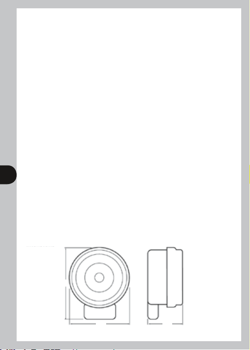
1.4 Dimensions
131
100 76
Page 4

2.0 Installation Instructions:
2.1 Safety Information
The RTS113/RTS113Q/RTS114/RTS114Q should only be installed by a trained electrician.
The I.E.E. wiring regulations must be observed. The supply must be disconnected before
wiring commences and a means of isolation with a separation of 3mm in each current
path must be provided in the supply to the RTS unit. This product must not be installed
where it may come into direct contact with liquids. The RTS unit is suitable for fixed
wiring applications only.
2.2 Electrical Interference
Despite elaborate safety precautions, exceptionally strong electrical fields may interfere
with any electronically controlled timeswitch. We therefore recommend that you observe
the following points before installation:
• Suppress interference caused by inductive loads by means of an RC filter and/or
varistor (VDR).
• Do not install the RTS unit in close proximity to sources of interference,
eg transformers, contactors, Pcs and TV sets.
2.3 Wiring Diagrams
Fig 1a
RTS113/
RTS113Q
3 4
2
3
1
L SL
N N
2.4 Installation
Three fixing holes B
countersunk with
central knock out
Load
Fig 1b
RTS114/
RTS114Q
Voltage between V
and COM – any AC
voltage up to 250V
V
COM COM
L
N
Fixing screw A for terminal cover which also retains
the plug-in timeswitch assembly
Transparent
cover
SV
LOAD
Lug D
on cover
Lug C
on base
Fig 2
Three cable holes leading
to terminals 1, 2 and 3
(terminal cover removed)
Fig 4a RTS113/RTS113Q Fig 4b RTS114/RTS114Q
Base
Base
Terminal
cover
Fig 3
Base
Three cable holes leading
to terminals 1, 2 and 3
(terminal cover removed)
4 cable/conduit knock outs in terminal
cover (2 at the bottom, 1 at each side)
Base
Page 5

Remove the transparent cover from the RTS unit by rotating it anticlockwise through 30° and
then pulling it clear. Unscrew the screw A (see fig. 3), remove the terminal cover and pull the
timeswitch plug-in assembly clear of the base. Drill out the three fixing screw holes in the base
(see fig. 2) and use 3 x No. 8 woodscrews (with wall plugs if necessary) to fix the RTS unit to the
mounting surface. Alternatively the unit may be fixed to panelling using 2B.A. or 5mm screws but
if the panelling is conducting it must be adequately earthed in accordance with the I.E.E. wiring
regulations. In either case ensure that the screws are countersunk and tightened fully so that
there is no projection above the surface of the base. Strip 8mm of insulation from the end of each
wire and insert in the appropriate terminal (see figs 1 and 4). Securely tighten the terminal screws
onto the wires and push the timeswitch plug-in assembly fully home into the base to ensure
electrical safety. Remove the appropriate knock-outs in the terminal cover and locate the cover
over the cables or conduit, securing with screw A. After commissioning the installation replace the
transparent cover by pushing over the base and rotating clockwise ensuring that lugs C and D on
the base and cover are lined up as in fig. 2.
If the transparent cover is required to be locked this can be achieved by a padlock through the
lug C with lugs C and D in the position shown in fig 2. Alternatively the holes in lugs C and D can
be lined up, wired and sealed. The fixing screw A (fig 3) securing the terminal cover can also be
secured by wiring and sealing.
3.0 Programming:
3.1 24 hour programming and clock time/day of week setting.
Insert red tappets into the programme ring to set the required ON times and the blue
4
tappets to set the required OFF times (see examples in fig 5). Up to 24 complete ON/OFF
programmes can be set over a 24 hour period.
The correct day of the week (Wed) can now be set by referring to fig 5 and rotating the 24 hour
programme ring in a clockwise direction until the first digit of the appropriate half day marker
e.g. (Wed AM 1st digit 2) is opposite the time marker. The correct clock time (1500 hours
– see fig 5) can now be set by continuing to rotate the ring in a clockwise direction until the
appropriate marker on the 24 hour ring is above the time marker.
The condition of the red (24 hour) control now needs to be checked and changed if necessary by
turning the red control shaft in an anticlockwise direction using a small screwdriver. If the last
tappet on the 24 hour ring to pass the time marker in a clockwise direction is blue the slot in the
red control shaft needs to be aligned with any
tappet is red. Next ensure that all the seven day segments have their screwdriver slots parallel to
the 7 day ring If not, turn in a clockwise direction with a small screwdriver until they are.
Note: Excess force used to turn a segment in an anticlockwise direction will damage
the timeswitch. Finally set the 7 day (blue) output control to ON if necessary by turning the
blue control shaft with a small screwdriver in a clockwise direction until the screwdriver slot in
the shaft is aligned with any ■ symbol. Finally ensure permanent override indicator is set to AUTO.
The RTS113/RTS113Q is now ready for service as a 24 hour timeswitch.
Note: Excess force used to rotate the programme ring and the blue control shaft
in an anticlockwise direction or the red control shaft in a clockwise direction will
damage the timeswitch.
symbol (OFF) and any ■ symbol (ON) if the last
•
Page 6

7 day output
control (blue)
24 hour output
control (red)
Time marker
Permanent override
indicator
Segment set to change
7 day output
Fig 5
3.2 Half day and day omit programming and 7 day control setting.
This is required only if the programme set on the 24 hour ring is not needed for one or more half
days. An example is shown in fig 5 where the requirement is to have no operation on Thursday
(day 4) afternoon and all day Friday (day 5). The 7 day switch segments between 4 and 4 (midday
Thursday) as well as between 5 and 6 (midnight Friday) have been turned anti-clockwise with a
small screwdriver until the segment slot is aligned radially
changed as each of these segments passes the time marker. Excessive force used to turn a
segment anticlockwise will cause damage.
The 7 day (blue) output will also need to be set manually in the right initial condition. In the
example shown in fig 5 when the time marker points within the period midday Thursday – to
midnight Friday the setting will be
by using a screwdriver to turn the 7 day control in a clockwise direction until the slot points to
a • for OFF or a ■ for ON. In the situation shown in fig 5 the control needs to be set ON.
Finally ensure permanent override indicator is set to AUTO. The 7 day control must only be
rotated in a clockwise direction. The screwdriver slot in the control is shaped to
prevent rotation in the opposite direction.
3.3 Override to next programme change.
The red 24 hour control can be turned anticlockwise by one click. This will change the
present output of the RTS unit and will last until the next programme change.
The 7 day control must only be rotated in a clockwise direction. The screwdriver
slot in the control is shaped to prevent rotation in the opposite direction.
3.4 Permanent Override ON.
The RTS unit can be permanently overridden ON by pressing the red button on the outside of
the case and transparent cover adjacent to the 7 day and 24 hour controls. The override can be
terminated by pressing the button again. The state of the timeswitch either permanently ON
or in Auto is indicated by the pointer adjacent to the 7 day and 24 hour controls.
– OFF and outside this time period ■ – ON. This is achieved
•
OFF at 1200 (blue tappet)
ON at 0900 (red tappet)
AM marker bar
ON at 2000 (red tappet)
OFF at 2200 (blue tappet)
so that the 7 day output will be
Page 7

3.5 Programming Overview
7 day output
control (blue)
24 hour control
(red)
Red tappet
Blue tappet
2 segments set to give
changes to 7 day control
at midday Thursday and
midnight Thursday. With
7 day control set at
above no 24 hour operation
will occur between midday
and midnight each Thursday.
24 Hour Ring
Red tappet for ON operation.
6
Blue tappet for OFF operation.
Fig 2 shows an ON period starting at 1200 and ending at 1500.
24 Hour Control
If last tappet past time marker was blue 24 hour control
should show
7 Day Ring
Segments with screwdriver slots positioned radially cause a change on the 7 day control.
The 7 day contacts are in series with the 24 hour contacts controlling the timeswitch output,
so the 7 day contacts need to be closed (
Finally ensure permanent override indicator is set to AUTO.
4.0 5 Year Guarantee
In the unlikely event of this product becoming faulty, due to defective material or manufacture,
within 5 years of the date of purchase, please return it to your supplier with proof of purchase
and it will be replaced free of charge.
Should you encounter any difficulty please contact our helpline on 020 8450 0515.
5.0 Additional Tappets
4 red and 4 blue tappets are supplied with the RTS unit. If further tappets are required they may
be obtained from Timeguard quoting the numbers 934 3 311 BLUE, 934 3 035 RED.
Please ring 020 8450 0515.
■
(ON)
(OFF) and ■ (ON) if it was red.
•
Fig 6
■
– ON) for the 24 hour contacts to be operational.
Clockwise direction for 24
Note: all other 7 day ring segments
are in the no change orientation
and are not shown for clarity
Time marker
hour and 7 day rings
Sunday markers
(in red)
7 day ring
24 hour ring
Radial slot
Page 8

For assistance with the product please contact:
HELPLINE
020 8450 0515
or email helpline@timeguard.com
For a product brochure please contact:
Timeguard Limited.
Victory Park, 400 Edgware Road,
London NW2 6ND
Sales Office: 020 8452 1112
or email csc@timeguard.com
67-058-78 (issue 3).
Zerofour – November 2013
 Loading...