

Page 1
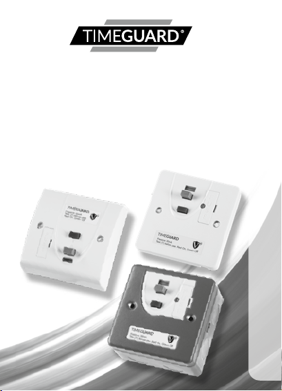
RCD Fused Connection Unit
RCD10 WP VN
RCD White Fused Connection Unit – Pass ive
RC D11 WP VN
RCD White Fused Connection Unit – Pass ive
RC D16ML N
RCD Metal Fused Con nection U nit – Passive
Installation & Operating Instructions
Page 2

1. General Information
These instructions should be read carefully and retained
for further reference and maintenance. The Timeguard
range of RCDs, provide protection against fire hazard and
rapid double pole disconnection from electric shock for the
appliance connected to it. They fully comply with BS7288
and BS1363-4 (including updates and amendments).
They are designed to mount on either a BS4662 recessed
box or a BS5733 surface mount box (plastic versions only).
Note: RCD – Residual Current Device.
2. Safety
• Before installation or maintenance, ensure the mains
1
supply to the RCD fused connection unit is switched off
and the circuit supply fuses are removed or the circuit
breaker turned off.
• It is recommended that a qualified electrician is
consulted or used for the installation of RCD fused
connection unit and install in accordance with the
current IEE wiring and Building Regulations.
• Check that the total load on the circuit including when
this RCD fused connection unit is fitted does not exceed
the rating of the circuit cable, fuse or circuit breaker.
• Electricity can be dangerous, use of an RCD should
not be regarded as a substitute for basic electrical
safety precautions.
Page 3

• Always test the RCD before use. If the test procedure
is not completed satisfactorily or an appliance continues
to trip the RCD seek professional advice and switch off
the appliance.
• To clean use a dry cloth only.
Do NOT use any liquid cleaners.
• The RCD should NOT be used when it could come into
contact with liquids or excessive atmospheric pollution.
• A warming of the casing during use is normal.
• Do NOT use outside the service conditions.
• For devices having a solid neutral, ensure the correct
polarity of the incoming supply connections should the
device trip automatically upon connection to the supply.
2
3. Wiring Tests – IMPORTANT
• Remove this product from the circuit if carrying out tests
(as described in the IEE Wiring Regulations) for earth
loop impedance, prospective short circuit current
and insulation resistance.
• Use the enclosed wiring label to ensure this is
carried out.
Page 4

4. Technical Specifications
General RCD Specifications
• Operating Voltage: 230V AC 50 Hz
• Max Current: Fully complies with the
• Rated Trip Current: 30mA
• RCD Type: Double Pole, suitable
• Breaking Capacity: 250A (Earth leakage)
• Through Fault Withstand: 1500A
• Operating Temperature
3
Range: -5°C to 40°C
• Trip Speed: Less than 40msec
• Fixed Cable Capacity: 1x 8mm² or 2x 4mm²
• Flexible Cable Capacity: 10.5mm diameter maximum
• Altitude: <2000m
• CE Compliant
current rating requited by
BS1363-4 (including updates
and amendments)
for 2 and 3 wire applications
at 150mA residual current
or 3x 2.5mm²
Page 5

Note: The RCD fused connection units are latching (passive)
versions. If set, this will retain closed contacts if the mains
supply is interrupted – essential for applications such
as freezers.
RCD10WPVN
• Minimum Box Depth
Required: 25mm
• Dimensions (H x W x D): 85mm x 85mm x 52mm
RCD11WPVN
• Minimum Box Depth
Required: 25mm
• Dimensions (H x W x D): 85mm x 85mm x 42mm
4
RCD16MLN
• Minimum Box Depth
Required: 40mm
• Dimensions (H x W x D): 87mm x 87mm x 60mm
Page 6

RCD10WPVN
BS1362 Fuse holder Red Test (T) button
Grey Reset button (R) Status indicator shows Red
5
RCD11WPVN
Status indicator shows Red for ON,
Green for OFF
Grey Reset button (R) Red Test (T) button
for ON, Green for OFF
BS1362 Fuse holder
Page 7

RCD16MLN
Status indicator shows Red for ON,
Green for OFF
6
Grey Reset button (R) Red Test (T) button
5. Pack Contents
• 1x RCD Fused connection unit.
• 2x 3.5mm diameter fixing screws.
• 1x Warning label.
• 1x Instruction manual.
• 1x Cable clamp and cable clamp screw
(Not RCD16MLN).
BS1362 Fuse holder
Page 8

6. Installation
• The RCD should form part of a 30A ring main or
terminate a spur off a 30A ring main. The cable
connecting the supply to the RCD should be either:
2x 2.5mm² for the ring main or 1x 2.5mm for the spur.
• Fit the appropriate BS1362 fuse to suit the load
appliance to be connected.
• The cable connecting the load appliance should be rated
according to the fuse fitted to the connection unit.
• Make sure to tighten all screw terminals onto
exposed wires.
• Ensure that there is both sufficient length of the supply
cable tails(s) to enable easy wiring.
6.1 Ensure the mains supply is switched off and the circuit
7
supply fuses are removed or the circuit breaker turned off.
6.2 Connect the incoming 230V 50Hz supply and outgoing
load cables to the relevant terminals ensuring correct
polarity is observed and that all bare conductors are
sleeved (see section 7. Connection Diagrams).
6.3 A front cable exit cut-out is provided on the RCD10WPVN
and RCD11WPVN units. The RCD10WPVN has a preinstalled removable blanking plate and the RCD11WPVN
front cable exit needs to be cut-out manually.
6.4 If the front exiting cable cut-out is required:-
1. Cut-out the front cable exit or remove the blanking
plate (you can discard the blanking plate at this stage).
2. Remove the cable grip and clamp screw from the
accessory pack.
Page 9

3. Secure the load cable to the unit using the cable clamp
and clamp screw.
6.5 Finally secure the unit to the back box with the fixing
screws provided, forming the cables during installation
to avoid any entrapment and cable damage.
Do not over tighten.
RCD16MLN Metal Clad Back Box
6.6 Note the correct orientation of the back box
(the word TOP should be the correct way up).
6.7 Lock rings, with a maximum thickness of 4.2mm and
a maximum diameter of 25.7mm must be used on the
inside of the back box. The gland or conduit must not
project into the back box beyond the lock ring, a male
8
adapter should be used within the back box along with
a female coupler on the outside to terminate the cable
glands or conduit.
Page 10

BS7288:2016
230V ~ 13A
BS1363-4
7. Connection Diagrams
RCD10WPVN
The terminals are marked as follows on the rear of the unit;
9
Neutral Supply
Earth Terminals
Cable clamp
and screw
Live SupplyLive LoadNeutral Load
Removable
blanking plate
Page 11

BS7288:2016
13A
230V~
BS1363-4
RCD11WPVN
The terminals are marked as follows on the rear of the unit;
Live Supply
Earth Terminals
Neutral Supply
10
Front cable
exit cut out
Cable clamp
and screw
Live Load
Neutral Load
Page 12

BS7288:2016
13A
230V~
BS1363-4
RCD16MLN
The terminals are marked as follows on the rear of the unit;
Live Supply
Earth Terminals
Neutral Supply
11
Cable clamp
and screw
Live Load
Neutral Load
Page 13
230V 50Hz Mains Supply
Live Supply (Brown or Red) to L IN
Neutral Supply (Blue or Black) to N IN
Earth (Green/Yellow) to
Load
Switch Live Supply (Brown or Red) to L OUT
Neutral Load (Blue or Black) to N OUT
Earth (Green/Yellow) to
8. General RCD Operation
Note: Always test the RCD before use
12
To Test
8.1 RESET – Press the Grey/Blue Reset button marked (R),
the status indicator should show Red.
8.2 TEST – Press the Red Test button marked (T), the status
indicator should show Green. This indicates the RCD
had been tripped and power has been disconnected.
8.3 RESET – Press the Grey/Blue Reset button marked (R)
again, the status indicator should show Red.
Page 14

• If all the above operations work satisfactorily,
the RCD is safe for use.
• If the procedure is not completed satisfactorily,
DO NOT use the RCD and see professional advice.
• In applications such as hand driers it may not be
practical to expect each user to test before use. In this
case we suggest an appropriate person applies the test
routine twice a day.
To Use
• After satisfactorily testing the RCD, any connected
appliance may be switched ON, and used in confidence
that the use is protected from electric shock by rapid
disconnection.
If the RCD Trips
13
• Turn the appliance switch OFF, press the Grey/Blue Reset
(R) button and note that the status indicator turns Red.
Switch the appliance ON and of the RCD trips again,
switch OFF the appliance and DO NOT use it, as it may
be faulty. Seek professional advice.
Page 15

3 Year Guarantee
In the unlikely event of this product becoming faulty due
to defective material or manufacture within 3 years of the
date of purchase, please return it to your supplier in the
first year with proof of purchase and it will be replaced free
of charge. For years 2 to 3 or any difficulty in the first year
telephone the helpline on 020 8450 0515.
Note: A proof of purchase is required in all cases.
For all eligible replacements (where agreed by Timeguard)
the customer is responsible for all shipping/postage charges
outside of the UK. All shipping costs are to be paid
in advance before a replacement is sent out.
14
Page 16

If you experience problems, do not immediately
return the unit to the store.
Telephone the Timeguard Customer Helpline;
HELPLINE
020 8450 0515
or email helpline@timeguard.com
Qualified Customer Support Co-ordinators will be on-line
to assist in resolving your query.
For a product brochure please contact:
Timeguard Limited.
Victory Park, 400 Edgware Road,
London NW2 6ND
Sales Office: 020 8452 1112
or email csc@timeguard.com
www.timeguard.com
67.058.611 (Issue 2)
TG51764 – March 2020
 Loading...