

Page 1
RCD Fused Connection Unit
Model: RCD10WPV
RCD Double Sockets
Models: RCD05WAV, RCD06WPV
RCD07MAV, RCD08MPV
Installation & Operating Instructions
Page 2
General
The Timeguard range of RCDs provides protection against fi re
hazard and rapid double pole disconnection from electric shock
for the appliance and cable connected to it. They comply fully
with BS7288 and BS1363. They are designed to mount on either
a BS4662 recessed box or a BS5733 surface mount box (plastic
versions only).
Note: RCD – Residual Current Device.
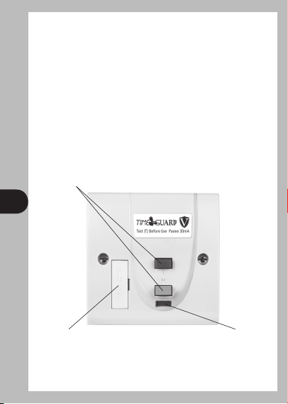
RCD Fused Connection Unit
Model: RCD10WPV.
Colour coded positive action
buttons for Testing and
Resetting the RCD.
1
BS1362 fuse holder. Status indicator shows red for‘ON’.
The RCD fused connection unit is a latching (passive) version.
If set, this will retain closed contacts if the mains supply is
interrupted – essential for applications such as freezers.
Page 3
Pack Contents
1 RCD10WPV.
2 3.5mm diameter screws 32mm long.
1 Warning label.
1 Instruction leafl et.
1 Cable clamp and cable clamp screw.
L
OUT
BS 7288
BS 1363-4
N
OUT
13A
230V
L
IN
2
N
IN
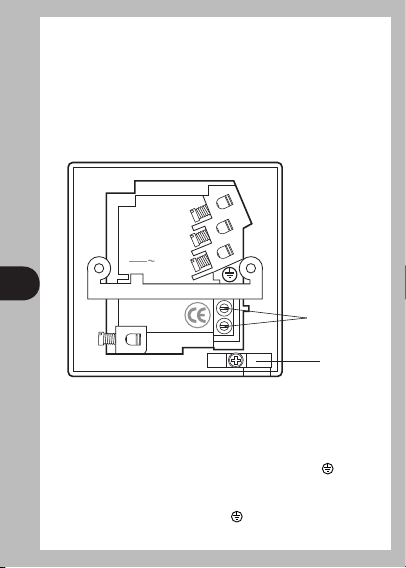
Fused Connection Unit Connections
Supply Brown (Red) (Live) to L IN.
Supply Blue (Black) (Neutral) to N IN.
Supply Bare Earth Wire, sleeved Green/ Yellow, to E
Load Brown (Live) to L OUT.
Load Blue (Neutral) to N OUT.
Load Green/ Yellow (Earth) to E
can be used as convenient).
Earth terminals
Cable clamp
.
(one or both terminals
Page 4
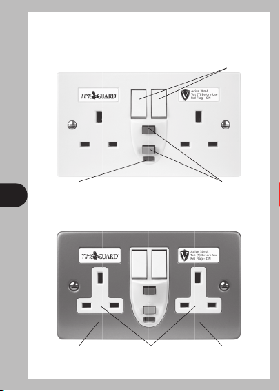
RCD Double Sockets
White plate models: RCD05WAV, RCD06WPV.
Switched for convenience
and extra safety.
Status indicator shows
red for ‘ON’.
3
Metal clad models: RCD07MAV, RCD08MPV.
Metal clad construction
giving the best protection
against physical damage.
Colour coded, positive action buttons for
Testing (T) and Resetting (R) the RCD.
RCD unit protects
both socket outlets.
Fully meets the
BS1363 current
rating.
Page 5

The RCD socket comes in two forms, a latching (passive) version
with the penultimate letter set to ‘P’ in the type number and a
non-latching (active) version which has the penultimate letter
set to ‘A’.
The latching version, if set, will retain closed contacts if the
mains supply is interupted – essential for applications such as
freezers.
The non-latching version, if set, allows the contacts to open
if the mains supply is interrupted – a ‘safety must’ for
applications such as power tools.
Pack Contents
1 RCD05WAV, RCD06WPV, RCD07MAV, RCD08MPV.
2 3.5mm diameter screws 35mm long.
1 Warning label.
1 Instruction leafl et.
4
1 Metal surface box (RCD07MAV, RCD08MPV only).
13A
240V
BS7288
LN
Page 6

Socket Connections
Supply Brown (Red) (Live) to L
Supply Blue (Black) (Neutral) to N
Supply Bare Earth Wire, sleeved Green/ Yellow, to E
(for double sockets one or both terminals can be
used as convenient)
Metal Clad
Lock rings, with a maximum thickness of 4.2mm and a
maximum diameter of 25.7mm must be used on the inside of
the box on TL (top left) and TR (top right) entries to secure the
gland or conduit. The gland or conduit must not project into the
box beyond the lock ring, a male adaptor should be used within
the box on TC (top centre) and BC (bottom centre) entries along
with a female coupler on the outside to terminate cable glands
or conduit.
5
Cable gland or conduit entry in
TC or BC using a male adaptor
with a female coupler.
20mm knockout positions.
View of inside of RCD socket outlet back box.
TL TC TR
BL BC BR
Cable gland or conduit
entry in TL or TR using a
lock ring inside the box.
Page 7

General RCD Instructions
The RCD should form part of a 30A ring main or terminate
a spur off a 30A ring main. The cable connecting to the supply
to the RCD should be either: 2 x 2.5mm
or 1 x 2.5mm
RCD10WPV only – Fit the appropriate BS1362 fuse to suit the
load appliance to be connected.
The cable connecting the load appliance (spur only) should be
rated according to the fuse fi tted to the connection unit.
Strip sleeving and insulation and cut wires as required for the
appliance cable. Tighten the screw terminals onto the exposed
wires maintaining the correct polarity, then fi t the cable into the
cable clamp groove and tighten down the clamp box to retain
the cable.
6
All RCDs – Ensure that there is both suffi cient length of the
supply cable tail(s) to enable easy wiring.
Strip sleeving and insulation and cut wires as required.
Tighten the screw terminals onto the exposed wires maintaining
correct polarity and offer the unit up to the wall box, forming the
cable as required.
Screw RCD to wall box and tighten suffi ciently to hold in place.
Do not over tighten.
2
for the spur.
2
for the ring main
Page 8

General RCD Operation
Always test the RCD before use.
To t est:
RESET – press the grey/ blue button marked Reset (R), the status
indicator should show red.
TEST – press the red button marked Test (T), status indicator
should show black. This indicates that the RCD has been tripped
and power has been disconnected from the outlet.
RESET – press the grey/ blue button marked Reset (R) again, the
status indicator should show red.
If all the above operations work satisfactorily, the RCD is safe for
use. If the procedure is not completed satisfactorily do not use
the RCD and seek professional advice.
In applications such as hand driers it may not be practical to
7
expect each user to test before use. In this case we suggest an
appropriate person applies the test routine twice a day.
To use:
After satisfactorily testing the RCD, any connected appliance
may be switched on, and used in the confi dence that the user is
protected from electric shock by rapid disconnection.
If the RCD trips:
Turn the appliance switch off, press the Reset R button and note
that the status indicator turns red. Switch the appliance on and
if the RCD trips again, switch off the appliance and do not use
it, as it may be faulty. Seek professional advice.
Page 9

General RCD Specifi cations
Voltage: 230V AC 50Hz
Max Current: Fully complies with the current
rating required by BS1363
Rated Trip Current: 30mA
RCD Type: Double Pole, suitable for
2 and 3 wire applications
Breaking Capacity: 250A (Earth leakage)
Through Fault Withstand: 1500A
Operating Temperature Range: -5° to 40°C
Trip Speed: Less than 40msec at 150mA
residual current
Fully Complies With: BS7288 & BS1363
8
Minimum Box Depth Required: 25mm
Fixed Cable Capacity: 1 x 8mm
or 3 x 2.5mm
Flexible Cable Capacity: 10.5mm diameter maximum
(RCD10WPV only)
2
or 2 x 4mm2
2
Page 10

Safety Issues to Remember
• Electricity can be dangerous, use of an RCD should not
be regarded as a substitute for basic electrical safety
precautions.
• Always test the RCD before use. If the test procedure is not
completed satisfactorily or an appliance continues to trip the
RCD seek professional advice and switch off the appliance.
• To clean use a dry cloth only. Do NOT use any liquid cleaners.
• The RCD should NOT be used when it could come into
contact with liquids or excessive atmospheric pollution.
• A warming of the casing during use is normal.
Wiring Tests – Important
Remove this product from circuit if carrying out tests
9
(as described in the IEE Wiring Regulations) for earth loop
impedance, prospective short circuit current and insulation
resistance.
Use the enclosed warning label to ensure this is carried out.
Page 11

10
5 Year Guarantee
In the unlikely event of this product becoming faulty due to
defective material or manufacture within 5 years of the date
of purchase, please return it to your supplier in the fi rst year
with proof of purchase and it will be replaced free of charge.
For the second and third years or any diffi culty in the fi rst year
telephone the helpline on 020 8450 0515.
Page 12

HELPLINE
020 8450 0515
or email helpline@timeguard.com
For a product brochure please contact:
Timeguard Limited.
Victory Park, 400 Edgware Road,
London NW2 6ND
Sales Offi ce: 020 8452 1112
or email csc@timeguard.com
Designed in the U.K. 67-058-340
Zerofour – April 2010
 Loading...