

Page 1
Conforms To
EC Directives
Surface Mount
Presence Detector
PDSM362/PDSM361
Instructions
Models PDSM362/PDSM361
Technical Specifications
Rated Voltage: 230V ~ ±10% 50Hz
Loads: PDSM362 (2 channels):
Load I ( L
separation)
Incandescent lamp: max. 2000W
This product must be
Mains halogen lamp: max. 1000W
protected by a fuse or
LV halogen lamp: max. 600VA
circuit breaker with a
Fluorescent lamp: max. 900VA/100µF
LED lamp: max 400W
maximum rating of
Load II (D1-D2) for HVAC:
10A or lower.
Max. 5A (cosØ =1) 250VAC or 30VDC
Max: 1/10HP (73W)
PDSM361 (1 channel):
Load I ( L
separation)
Incandescent lamp: max. 2000W
Mains halogen lamp: max. 1000W
LV halogen lamp: max. 600VA
Fluorescent lamp: max. 900VA/100µF
LED lamp: max 400W
Timer Adjustment PDSM362:
(constant adjustment): TIME1 (for lighting):
Adjustable from 5 sec. to 20 min.
(continuously adjustable)
TIME2 (for HVAC):
Adjustable from 10 sec. to 60 min.
(continuously adjustable)
PDSM361:
TIME: Adjustable from 5 sec. to 20 min.
(continuously adjustable)
LUX (light level) Adjustable from 10 LUX to 2000 LUX
Adjustment: (continuously adjustable)
Max. Detection Coverage: 360º cone shape from ceiling height of
2.5m giving 7m dia. coverage at floor
level (for affect of ceiling height on
coverage see section 3.1.1)
) for Lighting: µ (contact
) for Lighting: µ (contact
METER Adjustment: Adjustable continuously from
+ giving maximum detection
coverage at floor level to – giving a
substantially reduced detection
coverage at floor level
Operating Temperature: 0ºC to +45ºC
Environmental Protection: Class II, IP40
All procedures indicated in this manual must be
carried out by a professional installer.
1 Package Contents
Visual I.D.
Item Sensor Instructions Wood
screw screw (optional
Ø4 x Ø3 x purchase)
25.4mm 10mm
Quantity 1 1 2 2
Self-tapping
IR10
2 Product Description
2.1 Features
The PDSM362/PDSM361 controller is a ceiling surface mount
presence detector for indoor applications in commercial and
domestic locations. PDSM361 covers lighting applications only,
whereas PDSM362 can control lighting and HVAC
(heating, ventilating and air conditioning) applications.
Adjustment of Time and LUX values can be made either by the dial
controls on the sensor body or by the IR10 Infrared remote control.
•PDSM362hastworelaysforoutputsloadIandloadII:
load I is for lighting control and load II has voltage free contacts
for HVAC control which operate at all LUX (light) levels.
•Thesensorhasaveryhighdensityofsensitivebeamscoveringthe
detection area. These are evenly distributed ensuring no dead spots
and detection of the smallest movements.
•Eithersideorbottomcableentry.
•Built-inredLEDinsensorgivingconfirmationofremotecontrol
settings and easy test operation.
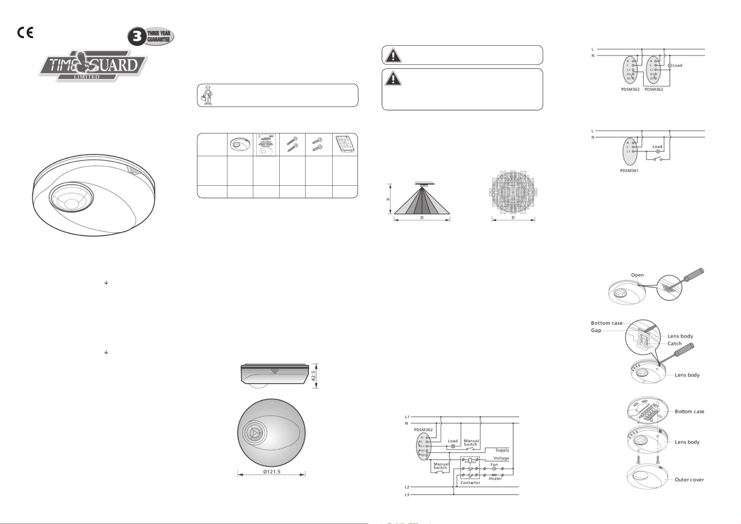
2.2 Dimensions (see Fig. 1)
Fig. 1
3 Installation and Wiring
Please disconnect power completely and read the
entire instruction manual carefully before installation.
PDSM362 – 6A breaker
A circuit breaker (250VAC,6A) type C according to EN60898-1
of load shall be installed in the fixed wiring for protection of load II.
PDSM361, PDSM362 – 10A breaker
A circuit breaker (250VAC,10A) type C according to EN60898-1
of load shall be installed in the fixed wiring for protection of load I.
3.1 Select the required location
3.1.1 Sensor adjustment
Fig. 2 shows the way coverage alters with ceiling height and with
adjustments of the METER dial setting.
Side View Top View (showing individual
beam pattern at floor level)
Fig. 2
Ceiling Height (H) Detection Coverage Diameter (D)
with METER on +
2m 7m
2.5m 7m
3m 10m
3.5m 12m
4m 12m
4.5m 12m
If the METER control is turned to – the coverage diameter is
substantially reduced.
We do not recommend the use of these units with ceiling heights
greater than 4.5m.
3.1.2 Helpful tips for installation
As the sensor responds to temperature change or moving heat sources,
please avoid the following conditions:
•Avoidhighlyreflectivesurfaceswithinthedetectionrange.
•Avoidmovableobjectse.g.curtainsandplantsinthedetectionrange
(these may cause erroneous detections when moved by air flow from
fans or air conditioner).
•Avoidheatsources(e.g.heatingvents,radiators,airconditionersand
filament lamps) in detection range.
•Avoidfansdrawingairacrossthesensorlens.
3.2 Wiring
3.2.1 Lighting and HVAC are controlled by one PDSM362 (see Fig. 3).
Fig. 3
3.2.2 Lighting is controlled by two PDSM362’s to enlarge
detection range (see Fig. 4).
Fig. 4
3.2.3 Lighting is controlled by a PDSM361 (see Fig. 5).
Fig. 5
3.3 Installation procedure
3.3.1 Insert large flat blade screwdriver into the groove as shown
each side in turn and twist (see Fig. 6) to remove outer cover.
3.3.2 To separate bottom case from lens body force a small flat blade
screwdriver into the hidden gap shown partially exposed in Fig. 7 then
push screwdriver in towards centre and lever bottom case assembly
away from lens body pins.
3.3.3 Remove cardboard and screws used to assemble and fix
the sensor (see Fig. 8).
Fig. 6
Fig. 7
Fig. 8
Page 2
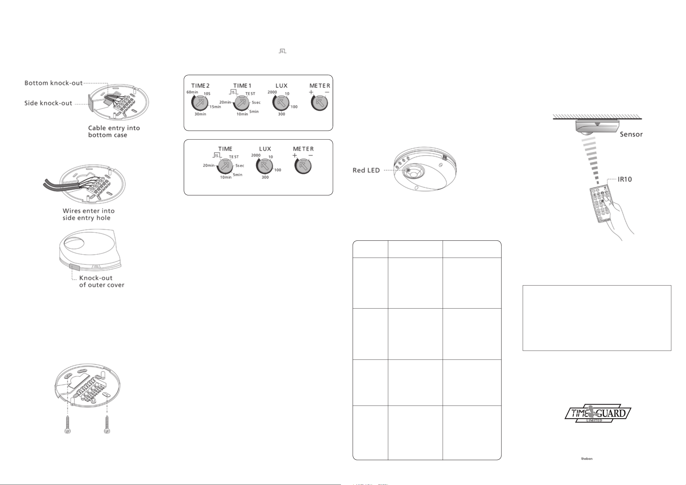
3.3.4 There are two methods of cable entry into the unit. One feeds
into the bottom case (Fig. 9-A), another feeds into the side of the
bottomcaseandoutercover(Fig.9-B).Selectyourpreferredcable
entry and score round the appropriate knock-out pattern in the bottom
case with a sharp knife. If side entry is chosen the knock-out pattern
in the outer cover will need to be scored as well. Push out the chosen
knock-outs and feed the wires through, then connect the wires to the
corresponding terminal blocks.
Fig. 9-A (Bottom entry)
4 Test and Operation
4.1 Time, LUX and Meter Controls
Following marked values (excepting TEST and
the values are continuously adjustable over the control range
(seeFig.11-A&Fig.11-B).
Fig. 11-A (PDSM362 control dials)
Fig. 11-B (PDSM361 control dials)
) are approximate,
4.2.3 Walk test
Turn supply on and wait at least 60 seconds for the system to
settle down.
Turn Time 1 control to the Test position. This means that the sensor
LED and load I will turn on for 2 seconds after triggering and then
be off for 3 seconds after which the sensor can be re-triggered.
The triggering is independent of light level.
The installer should move around in the detection area to establish
that it is all covered. If necessary the METER control dial should be
adjusted, after which the area should be walk tested again to
confirm coverage is as required.
To confirm that load 2 (HVAC) is operating correctly for a PDSM362,
carry out the following:Turn LUX (light level) to its minimum value (10 LUX) to stop load 1
(lights) from turning on. Then turn Time 2 (HVAC) to minimum value
(10s) and carry out a limited walk test to confirm correct operation
of load 2.
6 Optional Remote Control – IR10
PDSM362/PDSM361 can also be controlled by the infrared remote
controller IR10. As well as allowing remote setting of times and
light level the IR10 also enables continuous operation for 8 hours
in ON or OFF modes as well as continuously in detection mode
controlled by or independent of light level.
The IR10 is invaluable during commissioning enabling changes to
be made without resorting to ladders.
Further to this the IR10 can download stored settings from one
sensor to additional sensors in the same area.
Fig. 9-B (Side entry)
3.3.5 Insert the lens body pins into the bottom case contacts,
fasten it with screws firmly and snap on the outer cover (see Fig. 8).
3.3.6 Recheck and wipe slightly with a clean dry cloth if the sensor
surface is dirty.
3.3.7 There is a pattern of slots on the bottom case that should enable
the fixing holes of the previous unit to be used. Fasten bottom case
onto the ceiling with wood screws (see Fig. 10).
Fig. 10
3.3.8 Restore the power.
4.1.1 TIME control adjustment
These are delay times between the sensor being triggered and the
controller switching off assuming no further detections are made.
If there are additional detections the time delay applies from
the latest detection.
PDSM362:
TIME 1: Adjustable from 5 sec. to 20 min. (lighting). (Extendable to
30 min. and 60 min. when in use with the IR10 remote controller).
TIME 2: Adjustable from 10 sec. to 60 min. (HVAC).
PDSM361:
TIME: Adjustable from 5 sec. to 20 min. (lighting). (Extendable to
30 min. and 60 min. when in use with the IR10 remote controller).
4.1.2 LUX control adjustment
The LUX level below which the sensor will operate is adjustable
from 10 LUX (operation only after dusk) to 2000 LUX (operation at
any light level).
4.1.3 METER control adjustment
This control sets the diameter of detection coverage at floor level.
Assuming a ceiling height of 2.5m at the + end of the scale the
coverage diameter will be 7m, at the – end of the scale the coverage
diameter will be 1m.
The effect of METER control at other ceiling heights is shown in
section 3.1.
4.2 Test Mode
4.2.1 Sensor warm up
The detector will take a minimum of 60 seconds to warm up when the
power is connected to it for the first time or if the power is being
re-connected after being turned off.
During this period load I and the sensor LED will both be on. After the
warm up is finished the sensor will revert to operation according to
the settings of the controls on the sensor body.
4.2.2 LED function
There is a red LED (see Fig. 12) built into the sensor and visible through
the PIR lens that shows the status of the loads and enables testing to
be carried out without the loads being connected.
If the IR10 remote controller is in use the LED will flash to give
confirmation of the commands and adjustments made by the IR10.
Fig. 12
5 Troubleshooting
When the PDSM362/PDSM361 is not working as expected go
through the troubleshooting guide below.
Problem Possible Suggested
Cause Solution
Lights do not
turn on.
Lighting or
HVAC does not
turn off.
LED does not
turn on.
Nuisance
triggering.
1. Power is not turned on.
2. Incorrect control
dial setting.
3. Incorrect wiring.
4. Faulty load.
1. Incorrect time setting.
2. Incorrect wiring.
1. Out of detection range.
2. Power supply not on.
3 ‘TIME’ knob setting
isn’t on ‘Test’.
4. Incorrect wiring.
There are heat sources,
HVAC vents/fans, highly
reflective surfaces or
anything which may be
swayed by air movement
within the detection
coverage.
1. Switch on the power.
2.
Check if control dials are
set to the correct position,
then supply the power to
check if the LED will turn on.
3. Refer to wiring diagrams
(Fig. 3 to Fig. 6)
4. Replace the faulty load.
1.
Check that the correct delay
time is set on either TIME 1
or TIME 2 control dial.
Then determine if nuisance
triggering is keeping the
unit turned on.
2.
Make sure supply and load
wires are connected correctly.
1. Walk within the effective
detection range.
2. Switch the power on.
3. Turn the control dial
to ‘Test’.
4. Refer to wiring diagrams
(Fig. 3 to Fig. 5).
Avoid aiming the toward
any heat sources, such as
air conditioners, electric
fans, heaters or any highly
reflective surfaces.
Make sure there are no
swaying objects within the
detection coverage.
Fig. 13
3 Year Guarantee
In the unlikely event of this product becoming faulty due to
defective material or manufacture within 3 years of the date
of purchase, please return it to your supplier in the first year
with proof of purchase and it will be replaced free of charge.
For years 2 and 3 or any difficulty in the first year telephone
the helpline on
For assistance with the product please contact:
020-8450-0515
or email helpline@timeguard.com
For a product brochure please contact:
020-8452-1112
or email csc@timeguard.com
020 8450 0515.
HELPLINE
Timeguard Ltd.
A Group company
67-058-276 (Iss. 4)
 Loading...