

Timberk SWH FSL1 30 V, SWH FSL2 50 H, SWH FSL2 100 H, SWH FSP2 30 H, SWH FSP2 50 H User Manual [ru]
...Page 1

Instruction manual
Руководство по эксплуатации
FSL1 серия/series
FSL2 серия/series
FSP1 серия/series
Электрический
накопительный
водонагреватель
Модели/Models:
Outlook of devices, aslo colour scores can be revised without any special advance
notices.
Производитель вправе менять внешний вид прибора и цветовую гамму прибора без специального уведомления.
Electrical
storage water
heater
SWH FSL1 30 V
SWH FSL1 50 V
SWH FSL1 80 V
SWH FSL1 100 V
SWH FSL2 30 H
SWH FSL2 50 H
SWH FSL2 80 H
SWH FSL2 100 H
SWH FSP1 30 V
SWH FSP1 50 V
SWH FSP1 80 V
SWH FSP1 100 V
SWH FSP2 30 H
SWH FSP2 50 H
SWH FSP2 80 H
SWH FSP2 100 H
Page 2

TABLE OF CONTENTS
1. Important information
2. Precautions
3. Application of water heater
4. Performanceparameters
Technical characteristics
Dimensional features
5. Water heater description
6. Delivery set
7. Water heater installation
Location
Water heater mounting methods
Water heater mounting
Connection to water main
Connection to electric mains
Ground Fault Circuit Interrupter(GFCI)
8. Water heater control
Control panel
Water heater operation
9. Maintenance
10. Troubleshooting
11. Transportation and storage conditions
12. Wiring diagram
13. Disposal
14. Serial number and production date
Dear customer!
Thank you for your good choice. You purchased TIMBERK
2
electric storage water heater with an enameled internal tank. It
will serve you for a long time!
3
3
TIMBERK electric storage water heaters will provide a lot
of hot water and will automatically maintain the specified
3
temperature. They are perfect to provide hot water for country
4
houses, cottages, baths and other standalone amenity rooms.
5
5
6
7
7
Please, read this operation manual carefully prior to use of the water heater.
7
This operation manual contains important information regarding your
8
safety, as well as recommendations on the proper operation of the unit and
9
its maintenance.
9
Save this operation manual together with the guarantee card, cash register
receipt, if possible, cardboard box and packing material.
10
Different types of this device are described in this manual.
11
The purchased water heater can slightly differ from the one, described in
11
the manual, but that doesn’t affect methods of its use and operation.
11
12
13
13
14
14
14
1. IMPORTANT INFORMATION
IMPORTANT!
Important precautions and instructions, contained in
this manual, do not account for all possible modes and
situations to be encountered. It is vital to understand
that common sense, caution and thoroughness are the
factors that are impossible to be built-in in any product.
These factors must be taken into consideration by
a person, interested in proper operation of the unit.
The manufacturer does not bear any responsibility in
case when the unit or its parts are damaged during
transportation, as a result of improper installation,
voltage fluctuations, as well as if some part of the unit
was altered or modified.
2. PRECAUTIONS
A number of precautions is to be observed upon operation of the fan heater. Improper operation as a result of ignoring precautions may harm health
of the user and other people, as well as damage their property.
1. Any electrical appliance must be supervised when in operation, especially if there are children nearby. Make sure children do not touch the appliance.
2. Prior to installing the water heater, not connecting it to electrical main,
check and make sure the outlet for the water heater has a ground pin and
if it is properly earthed. If there is no earth circuit in your electrical main then
operation of the water heater is dangerous for your life.
3. Connect the water heater only to 220-230V, 50Hz main. If necessary,
find out parameters of your mains at power suppliers.
4. To prevent overheating and risk of fire, as well as damage of internal
electrical main, do no modify the power cord’s length and do no connect
the water heater through electrical extenders.
5. It is forbidden to switch on the water heater if it is not filled with water or
if water cannot go through a pressure safety valve.
6. Never use the water heater if it is broken.
7. Do not remove the water heater cover when it is in operation.
8. Immediately unplug the water heater from electrical main if strange
sounds, odor or smoke are coming from it.
9. Always unplug the water heater from electrical main during a thunderstorm.
10. Prior to cleaning and maintenance of the water heater unplug it from
electrical main. Cleaning and maintenance must be performed in compliance with instructions of this operation manual.
11. Do not use hazardous chemical substances to clean the water heater
and prevent their contact with the appliance.
12. To prevent electrical shock the damaged power cord must be replaced
only in manufacturer’s authorized service centers by qualified specialists.
13. To prevent electrical shock do not place the power cord nearby heating
devices and flammables or combustibles.
14. Do not press buttons on the control panel of the water heater and its
remote controller (for some models) otherwise but by your fingers.
15. Since temperature of water in the water heater can reach +75°C, when
it is in operation you should not place your body parts under hot water at
the first run.
To prevent burns you should adjust the temperature of the discharging
water.
16. Do not use the water heater for purposes not specified by this operation manual.
17. Do not use the water heater in an explosive or corrosive environment.
Do not store gas and other volatile flammable liquids next to the appliance
– it is very dangerous!
18. It is forbidden to make alterations in the design of the water heater or
modify it.
19. Any service operations must be performed by a specialized organisation and qualified specialists. Improper installation may cause voiding of
guarantee maintenance.
20. The water heater is not intended for use by children and persons with
reduced physical, sensory or mental capabilities, or a lack of experience
and knowledge, unless they have been given supervision or instruction
concerning use of the appliance by an individual responsible for their safety. Children should be supervised to ensure that they do not play with the
appliance.
3. APPLICATION OF WATER HEATER
Electric water heater is used to heat cold water from water supply. Unit is
for household use.
4. PERFORMANCE PARAMETERS
1. Completely automatic control: automatic water heating, continuous automatic water temperature control.
2. DROP Defense – leakage protection and protection against surplus pres-
sure within a tank (pressure safety valve).
HOT Defense – two-stage overheating protection (thermostat and temperature limiter).
ALL PROTECTION SYSTEMS ARE RELIABLE AND SAFE.
3. Pipes of heating elements are designed taking into account high heat load:
safe and reliable, with an increased service life.
4. NON CFC urethane foam insulation of increased thickness: excellent heat
2
www.timberk.com • electrical storage water heaterwww.timberk.com • electrical storage water heater
3
Page 3
insulation that allows to efficiently retain accumulated heat and save energy.
5. Temperature controller: accurate and reliable water temperature control.
6. FSP models equipped wiht temperature display shows current water tem-
perature in water heater tanks.
7. Internal tanks and all internal components are made out of SUS 304 stain-
less steel with walls 1.2 mm thick.
8. The water heater is equipped with an anode bar to protect the internal
tank from corrosion and decrease scale generation on the heating element.
Technical characteristics
Technical characteristics of water heaters are given below in Table 1, 2.
Table 1
Description Units
Rated voltage V/Hz 230~/50 230~/50 230~/50 230~/50
Rated current A 8.7 8.7 8.7 8.7
Rated power W 2000 2000 2000 2000
Stage power W 800/1200/2000 800/1200/2000 800/1200/2000 800/1200/2000
Tank capacity L 30 50 80 100
Rated
pressure
Protection
Class
Water
protection
class
Heating time,
at Δ 30 ºC
Appliance
dimensions
Weight kg
Factual year
energy
consumption
Constant daily
heating loss
SWH FSL1 30 V/
SWH FSL2 30 H
Mpa 0,7 0,7 0,7 0,7
– I I I I
– IPX4 IPX4 IPX4 IPX4
min 21 43 64 79
mm
550x435x238 855x435x238 991x493x270 1190x493x270
9,8 13,4 18,9 23,4
kW•h 335,8 452,6 481,8 518,3
kW•h /
day
0,98 1,23 1,33 1,45
SWH FSL1 50 V/
SWH FSL2 50 H
SWH FSL1 80 V/
SWH FSL2 80 H
SWH FSL1 100 V/
SWH FSL2 100 H
Table 2
Description Units
Rated voltage V/Hz 230~/50 230~/50 230~/50 230~/50
Rated current A 8.7 8.7 8.7 8.7
Rated power W 2000 2000 2000 2000
Stage power W 800/1200/2000 800/1200/2000 800/1200/2000 800/1200/2000
Tank capacity L 30 50 80 100
Rated
pressure
Protection
Class
Water
protection
class
Heating time,
at Δ 30 ºC
Appliance
dimensions
Weight kg 9,8 13,4 18,9 23,4
Factual year
energy
consumption
Constant daily
heating loss
SWH FSP1 30 V/
SWH FSP2 30 H
Mpa 0,7 0,7 0,7 0,7
– I I I I
– IPX4 IPX4 IPX4 IPX4
min 21 43 64 79
mm 550x435x238 855x435x238 991x493x270 1190x493x270
kW•h 335,8 452,6 481,8 518,3
kW•h /
day
0,98 1,23 1,33 1,45
SWH FSP1 50 V/
SWH FSP2 50 H
SWH FSP1 80 V/
SWH FSP2 80 H
SWH FSP1 100 V/
SWH FSP2 100 H
IMPORTANT!
Technical characteristics of the water heater you
purchased as of the date of manufacture correspond to
data, specified in the table. Technical characteristics and
scope of delivery can be revised without any prior notice.
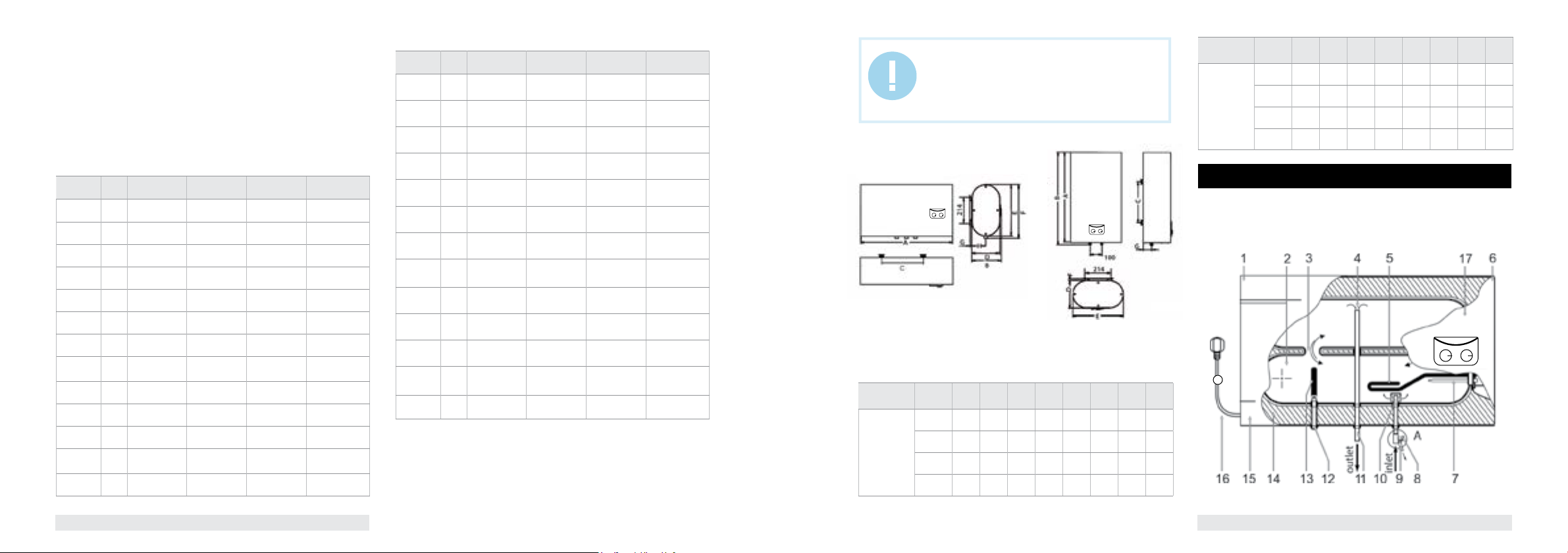
Dimensions
Series FSL2/FSP2
Series FSM2/FSQ2
Fig. 1 Fig. 2
Dimensions of water heaters (mm) are made in accordance with fig. 1, fig.
2 and fig. 3.
Table 3
Capacity, l A B C D E F G H
30 550 570 240 238 435 20
SWH FSL1/ SWH
FSP1 series
50 855 875 500 238 435 20
80 991 1011 450 270 493 20
100 1190 1210 550 270 493 20
Series FSL1/FSP1
Series FSM1/FSQ1
73 -
73 -
91,5 -
91,5 -
Capacity, l A B C D E F G H
30 550 266 240 238 435 450
SWH FSL2/ SWH
FSP2 series
50 855 266 500 238 435 450
80 991 298 450 270 493 510 20
100 1190 298 550 270 493 510 20
5. WATER HEATER DESCRIPTION
Fig.3 shows the design of the horizontal-type water heater.
Example is FSL/FSP.
FSL2
Fig. 3
20 73
20 73
91,5
91,5
4
www.timberk.com • electrical storage water heaterwww.timberk.com • electrical storage water heater
5
Page 4
1 – left composite protective cover
2 – water containing tanks
3 – system of flows between tanks (3 overflows)
4 – the upper part of the hot water intake tube
5 – heating element
6 – right composite protective cover
7 – temperature sensor case**
8 – composite pressure safety valve (be sure to install onto the cold water
supply tube) Pos. A
9 – emergency discharge of surplus water pressure (a small water leakage
is possible from the emergency discharge hole when the water heater is
operating. It is normal)
10 – inlet nozzle with a splitter
11 – hot water outlet nozzle
12 – emergency water discharge valve (can be used for water discharge
during cleaning of the internal tank surface upon its maintenance and anode
replacement)
13 – protective magnesium anode
14 – urethane foam heat insulation layer
15 – external decorative case
16 – power cable with GFCI*
17 - control panel
* Depending on the product batch, GFCI can be located not within the power cable electric plug.
** FSP model eguiped with temperature sensor
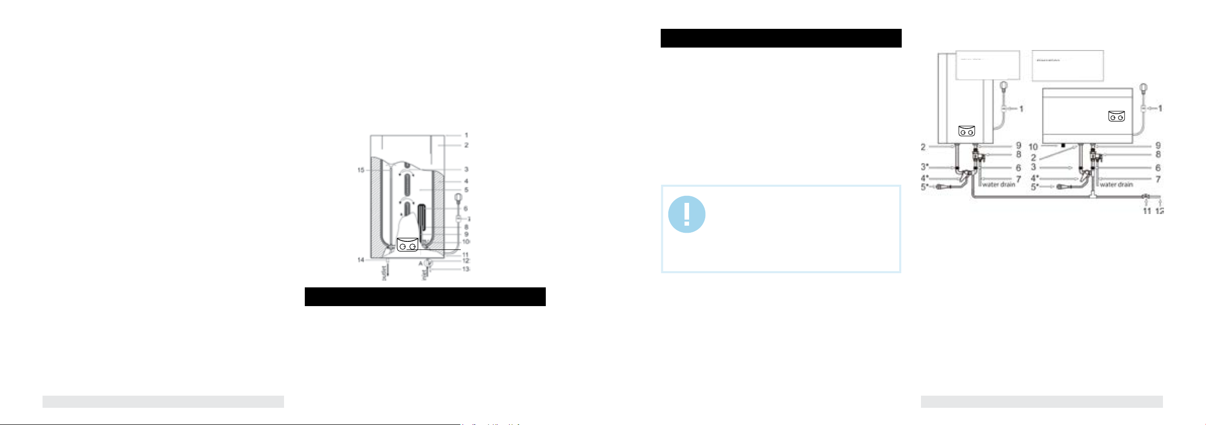
FSL1/FSP1 series
1 – the upper composite protective cover
2 – external decorative case
3 – system of flows
4 – urethane foam heat insulation layer
5 – internal tank
6 – heating element
7 – power cable with GFCI*
8 – thermostat sensor pipe
9 – protective magnesium anode
10 – inlet nozzle with a splitter
11 – the lower composite protective cover
12 – composite pressure safety valve (make sure to install onto the cold water
supply tube) Pos. A
13 – emergency discharge of surplus water pressure (a small water leakage is
possible from the emergency discharge hole when the water heater is operating.
It is normal)
14 – hot water outlet nozzle
15 – the upper part of the hot water intake tube
16 - control panel
* Depending on the product batch, GFCI can be located not within the power cable electric plug.
16
Fig. 4
6. DELIVERY SET
1. Water heater – 1 pc.
2. Anchor bolt – 2 pcs.
3. Pressure safety valve – 1 pc.
4. Operation manual – 1 pc.
5. Guarantee card – 1 pc.
6. Packing – 1 pc.
7. WATER HEATER INSTALLATION
Location
1. Electric water heater should be mounted on a firm wall. If the wall is not
robust enough to hold the weight equal to the doubled weight of the total
water heater weight, fully filled with water, then it should be mounted on a
special support.
2. The wall, where the electric water heater is to be mounted, must withstand
at least the double weight of the water heater, fully filled with water; there
must be no cracks and other damages on the wall. Otherwise it is necessary
to take measures to strengthen the mounting or mount the water heater on
a special support.
3. If a bathroom is too small, the water heater can be installed elsewhere,
unexposed to direct sunlight and unavailable for moisture. However, to
reduce heat losses in pipelines, the location, where a water heater is to be
installed, must be as close to the place, where hot water is used, as possible.
IMPORTANT!
The water heater must be mounted on a vertical wall
only the position, specified in Fig.3-4 (FSL1/FSP1 line
– vertically, FSL2/FSP2 – horizontally). Mounting of the
appliance in any other position or vertical or horizontal
tilting will inevitably result in failure of the water heater,
emergency situation and is considered a non-guarantee
case by the manufacturer.
Water heater mounting methods
Fig.5 shows the way to mount the water heater for one consumption point.
FSL1/FSP1
Vertical position
FSL2/FSP2
Horizontal position
Fig. 5
1. Power cord with GFCI**
2. Water outlet
3. Hot water supply adjustment cock*
4. Mixer*
5. Shower header*
6. Cold water supply adjustment cock*
7. Discharge pipe*
8. Composite pressure-relief valve
9. Water inlet
10. Magnesium anode – water discharge nozzle
11. Water main shut-off valve
12. Water main
13. Inlet piple
14. Outlet pipe
* not included in the delivery set
** Depending on the product batch, GFCI can be located not within the power cable electric
plug.
6
www.timberk.com • electrical storage water heaterwww.timberk.com • electrical storage water heater
7
Page 5
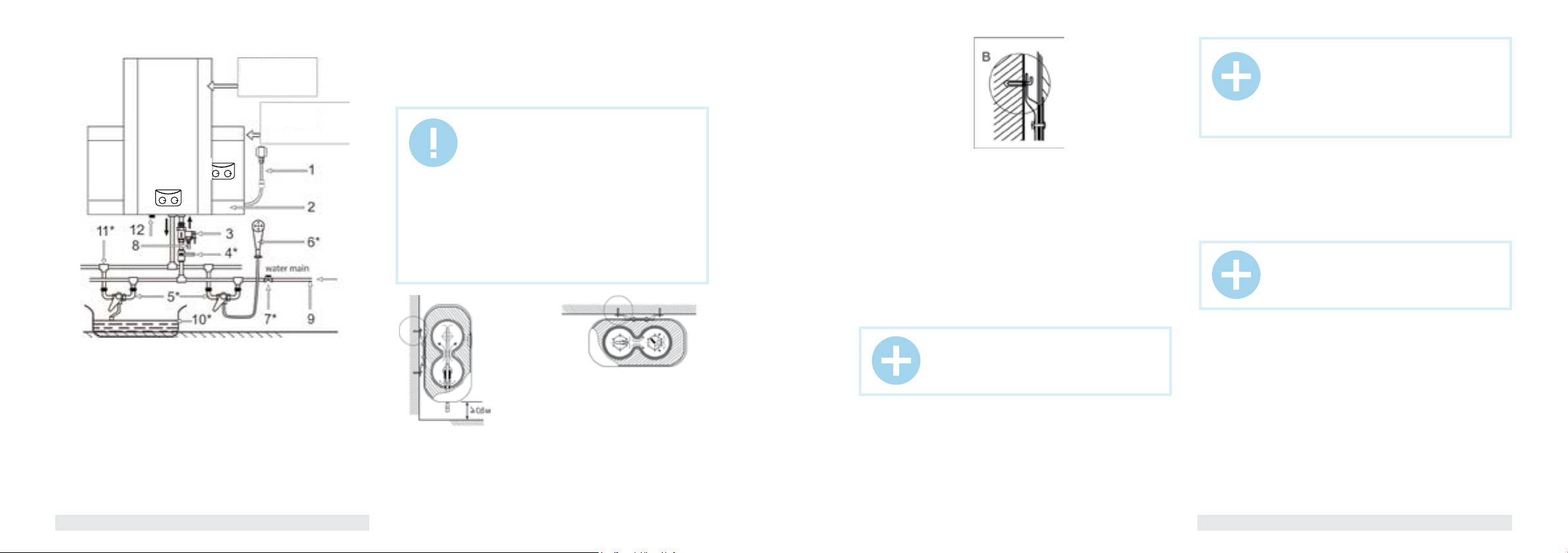
Fig. 7 shows the way to mount the water heater for one consumption point.
FSL1/FSP1
Vertical position
FSL2/FSP2
Horizontal position
Fig. 6
1. Power cord with GFCI**
2. Mounted water heater
3. Composite pressure-relief valve
4. Cold water supply valve*
5. Mixer*
6. Shower header*
7. Water main shut-off valve
8. Discharge pipe*
9. Water main
10. Bath*
11. T-joint*
12. Magnesium anode – water discharge nozzle
* not included in the delivery set
** Depending on the product batch, GFCI can be located not within the power cable electric
plug.
IMPORTANT!
Please, use accessories, provided by the manufacturer, to install the water heater. Electric water
heater must not be mounted on a wall prior you make
sure that the bracket is installed firmly and securely.
Otherwise the electric water heater may fall down
from the wall, which may cause its damage and
even serious accidents involving bodily injury. When
determining points for bolt holes, it is necessary to
provision some spare space between the lower part
of the water heater and the floor, and as to the FSL2/
FSP2 line there also must be some space between
the right side of the water heater and the wall on the
right, not less than 0.6 m to make it convenient to
perform maintenance if necessary.
(side view)
for FSL2/FSP2 series
(top view)
for FSL1/FSP1 series
Fig. 7
1. Electric water heater should be mounted on a firm wall. If the wall is not
robust enough to hold the weight equal to the doubled weight of the overall
water heater weight, fully filled with water, then it should be mounted on a
special support.
Fig. 8
2. After you chose the proper place to install the water heater, determine
points for holes for expansion hook bolts (to be determined in accordance
with the data sheet for the appliance you chose). Drill two holes of the
corresponding depth in the wall using a drill, dimensionally fit for expansion
bolts, enclosed with the water heater, insert bolts, turn the hook upwards,
securely tighten nuts and then hang the electric water heater on these hooks
(see Fig. 8).
3. Fix a power outlet to the wall. Requirements to the outlet are as follows:
230V/10A, single-phase, three-wired. It is recommended to place the outlet
on the right side above the water heater.
4. If a bathroom is too small, the water heater can be installed elsewhere,
unexposed to direct sunlight and unavailable for moisture. However, to
reduce heat losses in pipelines, the location, where a water heater is to be
installed, must be as close to the place, where hot water is used, as possible.
NOTE:
In places or on the wall, where water may get to, the
power outlet installation height must be not less than
1.8 m.
Connection to water main
1. The heater must be connected to water main with at least 0.1 MPa
pressure; maximum pressure is 0.7 MPa.
NOTE:
The water heater is the appliance, operating in such
a manner that pressure of water in the water heater
corresponds to the pressure of water in water main.
If pressure in the main exceeds 0.7 MPa, then it is
necessary to mount a pressure reducer before the
water heater so that pressure doesn’t exceed 0.7MPa.
2. G1/2 diameter pipes are used to connect the water heater to the water
pipeline.
3. To prevent a leakage when connecting pipes, use rubber sealing gaskets
on the threaded pipe ends.
4. Screw a relief valve to the inlet nozzle, marked blue and embossed arrow
of the water flow direction, so that the water flow direction coincides with
direction of the arrow on the valve’s case.
NOTE:
Do not mount additional accessories, such as a shutoff valve, between the relief valve and the inlet nozzle.
5. Water heater with the mounted valve must be connected to the water
main – install a shut-off valve at the water inlet point. You need to connect
a drain pipe to the opening of the pressure relief of safety valve. Next you
should put a drain pipe to the sewer.
6. Connect the desired number of consumption points to the outlet nozzle,
marked red.
7. Check leak integrity of joints: open the shut-off cock and one of the cock
assemblies. After the tank is filled with water, as evidenced by issue of water
from the cock assembly, shut the cock assembly and check the leak integrity
of all joints.
8
www.timberk.com • electrical storage water heaterwww.timberk.com • electrical storage water heater
9
Page 6
IMPORTANT!
If water in the installation location contains a large
amount of calcium, manganese or iron salts, then
IT IS NECESSARY to mount a respective filter in
the delivery system to reduce the amount of scale
generated in the tank and on the heating element.
Connection to electric main
IMPORTANT!
Prior to connecting the tank water heater, make sure
that the water heater is properly grounded. Proper
grounding is important to minimize electric shocks
and risk of fire. The power cord is equipped with a plug
with a grounding pin. The appliance must be used
with a properly grounded power outlet. If the outlet,
you are intending to use, is not properly grounded or
grounded by a time-delay fuse or a circuit breaker,
contact a qualified electrician to install a proper outlet.
1. The water heater is designed to be connected to 230V single-phase
electric main. Prior to connecting make sure that parameters of the electric
main in the place of connection correspond to parameters, specified on the
identification plate with technical parameters of the appliance. You should
follow the current electrical safety code when installing the water heater.
2. The power outlet must be properly grounded. The outlet must be
designed for rated current not less than 10A. The power outlet and plug
must always be dry to prevent current leakage. Regularly check if the
power plug is tightly connected to the outlet. Do it in the following order:
insert the power plug into the outlet, switch off the water heater after halfhour operation and unplug the cord, check if the plug is heated by your
hand. If the plug is heated over 50°C, then to prevent damages, accidents
and fire as a result of bad electrical contact, replace the outlet with a new
one. A specialist must do this.
3. Power cord of the appliance is a single unit with GFCI (Ground Fault
Circuit Interrupter).
IMPORTANT!
Wall outlet should be rated on voltage not lower than
10А, electric main cabel with cooper section not
lesser then 3х1,5 mm2 (for cooper).
Electric plug of the device corresponds one block
with GFCI.
Electric socket should be no lower, than 10A, power card with copper inner
part, cross-section of copper should be not less, than 3x1,5 mm
Electric plug has combined with GFCI.
2
.
IMPORTANT!
To provide reliable operation and safe use of the
water heater, prior to the first run check if it is properly
connected to the 230V AC mains. The water heater to
be connected must be securely linked with the earth
circuit of your electric mains. If the water heater is
not grounded, then in case of a short circuit GFCI,
supplied with the heater, may not operate. It is
dangerous.
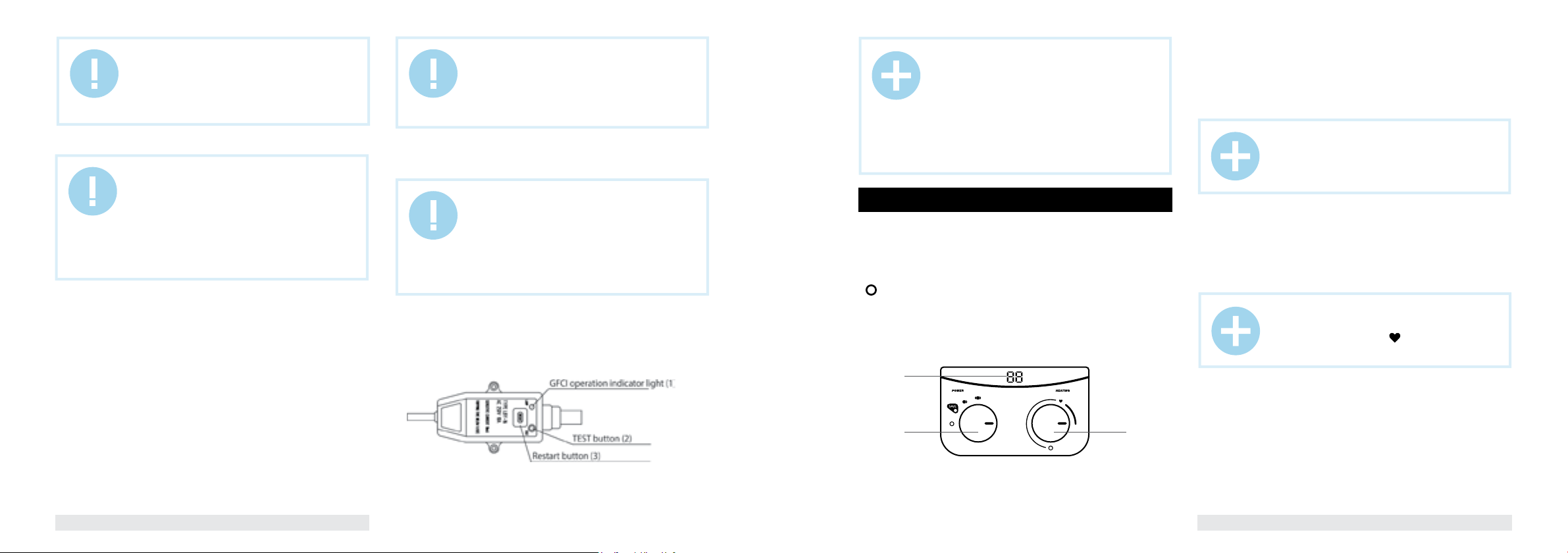
GFCI (Ground Fault Circuit Interrupter) (Fig. 9)
1. Connect the cable to the mains, indicator (1) will light up.
2. Press button (2) for testing, voltage will be cut off, indicator (1) will light
down and restart button (3) will go upwards.
3. Press button (3) to restart the appliance, voltage will be restored and
indicator (1) will light up.
Fig. 9
NOTE:
- if pressing test button (2) voltage is not cut off and/or
indicator (1) continues to be lighted, it means that GFCI
safety device is not operating properly.
- if pressing restart button (3) voltage is not restored
and/or indicator (1) doesn’t light up, it means that the
water heater is not operating properly. In both cases
disconnect the water heater and call the service center.
- to reduce the risk of an electric shock, do not
disassemble, remove or fill liquid in this appliance.
8. WATER HEATER CONTROL
Control panel
1. Thermostat handle
Please, use this handle to set the desired temperature of water. Turning the
knob in a clockwise direction you increase temperature of water.
2. Switcher of power modes
« » - means OFF position. Turning the knob in a clockwise direction you
increase power from 800W up to 2000W
3. Indicators lighting
If light are blue it means the water heater works, but a water is not heating
inside. If lights are pink/red it means the heating element heats a water
inside tank.
3
2
Fig. 10
1
Water heater operation
1. Switching on
1.1 At first, open one of the hot water outlet valves, then open the cold
water supply valve. The electric water heater will start filling with water.
When water flows from the hot tap freely, it means the water heater is fully
filled with water and you can close the hot water outlet valve.
NOTE:
During normal operation the cold water supply valve
must be set “open”.
1.2 Plug the power cord into the outlet, at that an indicator light on GFCI
and temperature controller handle lighting will light up and time will be
shown on the display.
2. Water heating temperature setting
2.1. Temperature can be set within the range 35°С-75°С, in increments
of 1°С.
NOTE:
When setting temperature, having reached the
optimal heating position “ ” (+58°С (+/- 2°С), you
will hear a sound signal (for some models).
2.2 The water heater automatically maintains water temperature. When
water temperature in the water heater reaches the temperature, set by the
user, the heating is automatically switched off. When water temperature
in the water heater drops to a certain level, the heating is automatically
switched off.
10
www.timberk.com • electrical storage water heaterwww.timberk.com • electrical storage water heater
11
Page 7

IMPORTANT!
Water may start dripping from the relief valve hole
during heating. It is impossible to avoid water leakage
and you must not prevent it since valve blocking
may cause rupture of the internal tank (in case of
equipment failure).
3. Temperature display (only for FSP series)
All FSP series models are equipped with temperature display shows
current water temperature in whater haeter tants.
9. MAINTENCE
Fig. 11
1. Check the power plug and outlet as often as possible. Secure electrical
contact and also proper grounding must be provided. The plug and outlet
must not heat excessively.
2. If the water heater is not used for a long time, especially in regions with
low air temperature (below 0°C), it is necessary to drain water from the
heater .
3. To ensure long reliable water heater operation, it is recommended to
regularly clean the internal tank and remove deposits on the electric heating
element of the water heater, as well as check condition of the magnesium
anode and, if necessary, replace it with a new one.
Fig. 12 Fig. 13
IMPORTANT!
The manufacturer provides an extended guarantee
for particular water heater components provided that
timely and proper routine maintenance is performed
by specialists of an authorized service center (see the
guarantee card).
4. Preventive operations must be performed upon strict observance of the
operation manual and safety precautions.
5. The water heater is equipped with a thermal switch, which cuts off power
supply of the heating element upon water overheating or its absence in the
water heater. If the water heater is connected to the mains, but water is
not heated and the indicator doesn’t light up, then the thermal switch was
switched off or not switched on. To reset the water heater to the operating
condition, it is necessary to:
- de-energize the water heater, remove the plate of the side / lower cover
for horizontal-type/vertical-type water heater respectively.
- for FSL2/FSP2 series horizontal-type water heaters: press the button,
located in the center of the thermal switch, placed near the heating element
(with a round shape), until it clicks, Fig.12;
- for FSL1/FSP1 series vertical-type water heaters: unscrew retaining nut of
the thermal switch, fastened on the flange of the heating element, turn the
thermal switch and press the button, located in the center of the thermal
switch, until it clicks; Fig. 13;
- if the button is not pressed and there is no clicking, then you should wait
until the thermal switch cools down to the initial temperature.
IMPORTANT!
If these actions had no positive result or the thermal
switch turns off repeatedly during a short period of
time, then you should de-energize the water heater,
cut off water supply and contact your local Timberk
Authorized Service Center for a consult or repair of the
appliance.
6. To drain water from the internal tank properly, you need to use the drain
hole (only for FSL2/FSP2 line) (it is necessary to unscrew a plug, covering
the drain hole), water can also be drained through a composite relief valve
(Fig. 11) (unscrew the composite relief valve drain knob screw and set the
drain knob to the upper position, at that hot water tap must be open, and
cold water supply valve must be closed).
7. Bear in mind to check serviceability of the relief valve every 14 days –
inspection method:
- turn the discharge lever to the left up until you feel the change of thread,
then water must start flowing from the valve’s hole. After checking the
water flow, return the lever to its initial position.
8. If necessary, wipe external surfaces of the heater by a damp cloth with
soap.
10. TROUBLESHOOTING
Possible malfunctions and troubleshooting methods
Table 4
Failure Possible causes Troubleshooting method
Heating indicator light doesn’t light up,
water is not heated
Water doesn’t flow from the hot water
discharge cock
Water temperature is too high Water temperature control system
Water leakage Seal at the point of pipe connection
Water flows from the appliance’s case Breaking of the internal tank
1. Temperature adjustment device
is broken.
2. Temperature limiter was actuated or
was not switched on.
3. Temperature limiter is broken. Contact a repairer, TIMBERK service
1. Water feed is cut off. 1. Wait until water supply is restored.
2. Water pressure is too low. 2. Switch on the water heater again,
3. Water supply exhaust valve is
closed.
is damaged.
is broken.
(corrosion)Seal at the point of the
heating element connection is broken.
Contact a repairer, TIMBERK service
center.
Switch on the temperature switch
following instructions on its activation.
(page 12)
center.
when normal water pressure restores.
Contact a repairer, TIMBERK service
center.
Replace the joint seal.
Contact a repairer, TIMBERK service
center.
11. TRANSPORTATION AND STORAGE
CONDITIONS
Temperature
requirements*
Humidity
requirements*
Transportation and
storage
We are exploring new technologies and we constantly improving the quality
of our products. That’s why specifications, design and accessories are
subject to change without any specific notice.
From -30° to +50°
From 15% to 85%
(without a condensate)
12
www.timberk.com • electrical storage water heaterwww.timberk.com • electrical storage water heater
13
Page 8

Серия FSL1/FSL2
temperature
limlter
Fig. 14
Серия FSP1
temperature
limlter
Fig. 15
12. WIRING DIAGRAM
hating power switch
termostat
heating element
termostat
hating power switch
heating element
indication
indication
indication light
power board
LED-display
indication
light
indication light
power board
light
light
temperature
sensor
13. DISPOSAL
The water heater should be disposed upon the end of life. You can obtain
detailed information on water heater disposal from a representative of local
authorities.
Device service life is 10 years.
NOTE:
Technical and any other characteristics of the
appliance can be revised.
Such changes may be introduced without warning and
prior notice to the consumers.
The manufacturer shall not be liable for changes in the
appliance’s wiring diagram that may be implemented
without notice to the consumers.
14. SERIAL NUMBER AND PRODUCTION DATE
Serial number, production month and year are included in ID LINE product
code. Sticker with production date is pasted on product surface.
СОДЕРЖАНИЕ
1. Важная информация
2. Меры предосторожности
3. Назначение прибора
4. Рабочие характеристики
Технические характеристики
Размерные характеристики
5. Описание водонагревателя
6. Комплект поставки
7. Установка водонагревателя
Местоположение
Способы монтажа водонагревателя
Монтаж водонагревателя
Подключение к водопроводной магистрали
Подключение к электрической сети
УЗО (устройство защитного отключения)
8. Управление водонагревателем
Панель управления
Эксплуатация водонагревателя
9. Обслуживание
10. Устранение неисправностей
Электрическая принципиальная схема
11.
Уважаемый покупатель!
15
16
17
17
17
18
19
20
20
20
21
22
23
23
24
24
24
25
26
27
27
Благодарим Вас за удачный выбор. Вы приобрели электрический накопительный водонагреватель Тimberk. Он прослужит Вам долго.
Электрические накопительные водонагреватели Тimberk
подготовят большое количество горячей воды и будут поддерживать заданную температуру автоматически. Они идеально подходят для снабжения горячей водой загородных
домов, коттеджей, бань и прочих индивидуальных бытовых
помещений.
1. ВАЖНАЯ ИНФОРМАЦИЯ
Просим внимательно ознакомиться с руководством по эксплуатации
перед использованием водонагревателя.
В данном руководстве по эксплуатации содержится важная информация, касающаяся Вашей безопасности, а также рекомендации по
правильному использованию прибора и уходу за ним. Сохраните руководство по эксплуатации вместе с гарантийным талоном, кассовым
чеком, по возможности, картонной коробкой и упаковочным материалом. В данном руководстве по эксплуатации описываются разные
виды данного типа устройства.
Приобретенный Вами водонагреватель может несколько отличаться
от описанного в руководстве, что не влияет на способы использования и эксплуатации.
ВНИМАНИЕ!
Важные меры предосторожности и инструкции, содержащиеся в данном руководстве, не включают
всех возможных режимов и ситуаций, которые мо
гут встречаться. Необходимо понимать, что здравый смысл, осторожность и тщательность являются
факторами, которые невозможно «встроить» ни в
один продукт.
-
14
www.timberk.com • electrical storage water heater
www.timberk.com • электрический накопительный водонагреватель
15
Page 9

ВНИМАНИЕ!
Эти факторы должен учитывать человек, который
заинтересован в надлежащей эксплуатации устрой
ства. Изготовитель не несет ответственности в случае повреждения прибора или его отдельных частей
во время транспортировки, в результате неправиль
ной установки, в результате колебаний напряжения,
а также в случае, если какая-либо часть прибора
была изменена или модифицирована.
-
-
2. МЕРЫ ПРЕДОСТОРОЖНОСТИ
При использовании водонагревателя, необходимо соблюдать ряд мер
предосторожности. Неправильная эксплуатация в силу игнорирования
мер предосторожности может привести к причинению вреда здоровью
пользователя и других людей, а также нанесения ущерба их имуществу.
1. Любой электроприбор должен находиться под наблюдением во время
его эксплуатации, особенно, если неподалёку от него находятся дети.
Внимательно следите за тем, чтобы дети не прикасались к прибору.
2. Перед установкой водонагревателя, не подключая его к электросети,
проверьте и убедитесь, что сетевая розетка для водонагревателя имеет
контакт заземления и правильно заземлена. При отсутствии заземляющего контура в вашей электросети эксплуатация водонагревателя опасна для жизни.
3. Подключайте водонагреватель только к сети 230В/50Гц. При необходимости выясните характеристики своей сети у поставщиков
электроэнергии.
4. Во избежание перегрева и риска возникновения пожара, а также
повреждения внутренней электрической сети, не изменяйте длину
сетевого шнура и не подключайте водонагреватель через электрические удлинители.
5. Запрещается включать водонагреватель, если он не наполнен водой или если обнаружена непроходимость воды через предохранительный клапан.
6. Никогда не используйте водонагреватель, если он неисправен.
7. Не снимайте крышки водонагревателя во время его работы.
8. Незамедлительно отключите водонагреватель от электрической
сети, если от него идут странные звуки, запах или дым.
9. Всегда отключайте водонагреватель от электрической сети во время грозы.
10. Перед началом чистки и технического обслуживания водонагревателя всегда отключайте его от электрической сети. Чистку и техническое обслуживание производите в соответствии с указаниями
данного руководства по эксплуатации.
11. Не используйте опасные химические вещества для чистки водонагревателя и не допускайте их попадания на него.
12. Во избежание опасности поражения электрическим током, поврежденный сетевой шнур должен меняться только в авторизованных
сервисных центрах изготовителя, квалифицированными специалистами.
13. Во избежание опасности поражения электрическим током не
размещайте шнур питания рядом с нагревательными приборами и
легковоспламеняющимися или горючими веществами.
14. Поскольку температура воды в водонагревателе может достигать
0
С, при использовании водонагревателя не следует подставлять ча-
75
сти тела под горячую воду при первом включении. Для предотвращения ожогов правильно отрегулируйте температуру вытекающей воды.
15. Не используйте водонагреватель, в целях, не предусмотренных
этим руководством по эксплуатации.
16. Не используйте водонагреватель во взрывоопасной или коррозионной среде. Не храните рядом с прибором бензин и другие летучие
легковоспламеняющиеся жидкости это очень опасно!
17. Запрещено вносить изменения в конструкцию водонагревателя
или модифицировать его.
18. Любые сервисные работы должны производиться специализированной организацией, квалифицированными специалистами. Неправильная установка может повлечь за собой отказ в гарантийном
обслуживании.
19. Водонагреватель не предназначен для использования лицами
(включая детей) с ограниченными физическими, сенсорными или умственными возможностями, обладающими недостаточным опытом
и знаниями, если они не находятся под наблюдением и не получили
инструкций по использованию устройства от лица, ответственного за
их безопасность. Необходимо, следить, чтобы дети не играли с прибором.
3. НАЗНАЧЕНИЕ ПРИБОРА
Электрический водонагреватель накопительного типа предназначен
для нагрева поступающей из водопровода холодной воды. Он применяется в бытовых целях.
4. РАБОЧИЕ ХАРАКТЕРИСТИКИ
Основные особенности
1. Полностью автоматическое управление: автоматический нагрев
воды, постоянный автоматический контроль температуры воды.
2. Система защиты:
- Drop Defense - защита от протечки и избыточного давления внутри
бака (предохранительный клапан)
- HOT Defense - двухуровневая защита от перегрева (термостат и
ограничитель температуры)
Все системы защиты являются надежными и безопасными.
3. Трубки нагревательных элементов спроектированы с учетом боль-
шой тепловой нагрузки: безопасные, надежные, с увеличенным сроком службы.
4. Пенополиуретановая NON CFC теплоизоляция увеличенной тол-
щины: отличная тепловая изоляция, которая позволяет эффективно
сохранять накопленное тепло и экономить электроэнергию.
5. Температурный контроллер: точное и надежное управление тем-
пературой воды.
6. Водонагреватель серии FSP оснащен дисплеем на панели управ-
ления, отображающим текущую температуру воды во внутреннем резервуаре водонагревателя.
7. Внутренний резервуар и все внутренние компоненты выполнены из
нержавеющей стали SUS 304 с толщиной стенок 1,2 мм.
8. Водонагреватель оснащен анодным стержнем для защиты от кор-
розии внутреннего резервуара и уменьшения образования накипи на
нагревательном элементе.
Технические характеристики
Технические характеристики водонагревателя приведены в таблице 1, 2.
Таблица 1
Наимено-
вание
Номининальное
напряжение
Номинальная
сила тока
Номинальная
потребляемая
мощность
Мощность по
ступеням
Объем л 30 50 80 100
Номинальное
давление
Класс защиты – I I I I
Класс влаго-
защиты
Время нарева
при Δ 30 ºC
Размеры
прибора
Фактическое
годовое
потребление
электроэ-
нергии
Постоянные
суточные
потери
Ед.
SWH FSL1 30 V/
изм.
SWH FSL2 30 H
В/Гц 230~/50 230~/50 230~/50 230~/50
A 8.7 8.7 8.7 8.7
Вт 2000 2000 2000 2000
Вт 800/1200/2000 800/1200/2000 800/1200/2000 800/1200/2000
МПа 0,7 0,7 0,7 0,7
– IPX4 IPX4 IPX4 IPX4
мин 21 43 64 79
мм 550x435x238 855x435x238 991x493x270 1190x493x270
Вес кг 9,8 13,4 18,9 23,4
кВт•ч 335,8 452,6 481,8 518,3
кВт•ч /
сут
0,98 1,23 1,33 1,45
SWH FSL1 50 V/
SWH FSL2 50 H
SWH FSL1 80 V/
SWH FSL2 80 H
SWH FSL1 100 V/
SWH FSL2 100 H
www.timberk.com • электрический накопительный водонагревательwww.timberk.com • электрический накопительный водонагреватель
1716
Page 10

Таблица 2
Наимено-
вание
Номининальное
напряжение
Номинальная
сила тока
Номинальная
потребляемая
мощность
Мощность по
ступеням
Объем л 30 50 80 100
Номинальное
давление
Класс защиты – I I I I
Класс влаго-
защиты
Время нарева
при Δ 30 ºC
Размеры
прибора
Фактическое
годовое
потребление
электроэ-
нергии
Постоянные
суточные
потери
Ед.
SWH FSP1 30 V/
изм.
SWH FSP2 30 H
В/Гц 230~/50 230~/50 230~/50 230~/50
A 8.7 8.7 8.7 8.7
Вт 2000 2000 2000 2000
Вт 800/1200/2000 800/1200/2000 800/1200/2000 800/1200/2000
МПа 0,7 0,7 0,7 0,7
– IPX4 IPX4 IPX4 IPX4
мин 21 43 64 79
мм 550x435x238 855x435x238 991x493x270 1190x493x270
Вес кг 9,8 13,4 18,9 23,4
кВт•ч 335,8 452,6 481,8 518,3
кВт•ч /
сут
0,98 1,23 1,33 1,45
SWH FSP1 50 V/
SWH FSP2 50 H
SWH FSP1 80 V/
SWH FSP2 80 H
SWH FSP1 100 V/
SWH FSP2 100 H
Размерные характеристики
Серия FSL2/FSP2
Серия FSM2/FSQ2
Рис. 1
Размерные характеристики водонагревателя (в мм) согласно рис. 1,
рис. 2 приведены в таблице 3.
Серия FSL1/FSP1
Серия FSM1/FSQ1
Рис. 2
Таблица 3
Объем, л A B C D E F G H
73 -
73 -
91,5 -
91,5 -
20 73
20 73
91,5
91,5
SWH FSL1/
SWH FSP1 серии
SWH FSL2/
SWH FSP2 серии
30 550 570 240 238 435 20
50 855 875 500 238 435 20
80 991 1011 450 270 493 20
100 1190 1210 550 270 493 20
30 550 266 240 238 435 450
50 855 266 500 238 435 450
80 991 298 450 270 493 510 20
100 1190 298 550 270 493 510 20
5. ОПИСАНИЕ ВОДОНАГРЕВАТЕЛЯ
На рис. 3 представлено устройство водонагревателя горизонтального
типа серии FSL2/FSP2. На рис. 4 представлено устройство водонагревателя вертикального типа серии FSL1/FSP1
Серия FSL2/FSP2
Вход
Выход
Рис. 3
1 - Левая комбинированная защитная крышка
2 - Внутренний резервуар
3 - Система переливов
4 - Верхняя часть патрубка забора горячей воды
5 - Нагревательный элемент
6 - Правая комбинированная защитная крышка
7- Трубка датчика термостата и датчика температуры**
8 - Комбинированный предохранительный клапан (требуется обяза-
тельная установка на патрубок подачи холодной воды) Поз. А
9 - Аварийный слив избыточного давления воды ( при работе водонагревателя возможно слабое подтекание воды из отверстия аварийного
слива. Это нормально)
10 - Входной патрубок с рассекателем
11 - Патрубок выхода горячей воды
12 - Патрубок резервного слива воды (может быть использован для
слива воды в момент чистки внутренней поверхности резервуара при
его техническом обслуживании и замены анода)
13 - Защитный магниевый анод (при его отсутствии отверстие выполняет роль резервного слива воды)
14 - Теплоизоляционный слой из пенополиуретана
15 - Внешний декоративный корпус
16 - Сетевой шнур с эл. вилкой и УЗО*
17 - Панель управления
*В зависимости от партии товара УЗО может быть расположено не в составе сетевого
шнура
** Датчик температуры доступен только для водонагревателя серии FSP1
Серия FSL1/FSP1
16
Рис. 4
Выход
Вход
www.timberk.com • электрический накопительный водонагревательwww.timberk.com • электрический накопительный водонагреватель
1918
Page 11

1 - Верхняя комбинированная защитная крышка
2 - Внешний декоративный корпус
3 - Система переливов (3 перелива)
4 - Теплоизоляционный слой из пенополиуретана
5 - Внутренний резервуар
6 - Нагревательный элемент
7- Сетевой шнур с эл. вилкой и УЗО*
8 - Трубка датчика термостата и датчика температуры**
9 - Защитный магниевый анод
10 - Входной патрубок с рассекателем
11 - Нижняя комбинированная защитная крышка
12 - Комбинированный предохранительный клапан (требуется обяза-
тельная установка на патрубок подачи холодной воды) Поз. А
13 - Аварийный слив избыточного давления воды ( при работе водона-
гревателя возможно слабое подтекание воды из отверстия аварийного
слива. Это нормально)
14 - Патрубок выхода горячей воды
15 - Верхняя часть патрубка забора горячей воды
16 - Панель управления
*В зависимости от партии товара УЗО может быть расположено не в составе сетевого
шнура
** Датчик температуры доступен только для водонагревателя серии FSP1
6. КОМПЛЕКТ ПОСТАВКИ
1. Водонагреватель - 1 шт.
2. Анкерный болт - 2 шт.
3. Предохранительный клапан - 1 шт.
4. Руководство по эксплуатации -1 шт.
5. Гарантийный талон - 1 шт.
6. Упаковка - 1 шт.
7. УСТАНОВКА ВОДОНАГРЕВАТЕЛЯ
Местоположение
1. Электрический водонагреватель следует устанавливать на прочной
стене.
2. Стена, на которой устанавливается электрический водонагреватель, должна выдерживать, как минимум, двойной вес водонагревателя, полностью заполненного водой, на стене должны отсутствовать
трещины и другие повреждения. В противном случае необходимо принять меры для усиления крепления или установить водонагреватель на
специальной опоре.
3. Если ванная комната слишком маленькая, водонагреватель можно
установить в другом месте, закрытом от прямого солнечного света и
недоступном для попадания влаги. Однако для снижения потерь тепла
в трубопроводах место установки водонагревателя должно находиться
как можно ближе к месту использования горячей воды.
ВНИМАНИЕ!
Водонагреватель должен быть установлен на
вертикальную стену строго в том положении, как
указано на рис. 3, 4 (серия FSL1/FSP1 – в вертикальном положении, серия FSL2/FSP2 – в горизонтальном). Установка прибора в любом другом
положении или перекос относительно вертикали
или горизонтали неизбежно приведет к выходу
водонагревателя из строя, созданию аварийной
обстановки и рассматривается производителем
как негарантийный случай.
Способы монтажа водонагревателя
Способ монтажа водонагревателя для одной точки потребления
представлен на рис. 5.
FSL2/FSP2
горизонтальное положение
горизонтальное положениевертикальное положение
*
*
*
*
Рис. 5
FSL1/FSP1
вертикальное положение
слив воды слив воды
1. Сетевой шнур с УЗО
2. Выходной патрубок
3. Кран регулировки потока горячей воды*
4. Смеситель*
5. Душевая насадка*
6. Кран регулировки потока холодной воды*
7. Сливная трубка*
8. Комбинированный предохранительный клапан
9. Входной патрубок
10. Магниевый анод-патрубок для слива воды
11. Отсечной кран водопроводной магистрали*
12. Водопроводная магистраль
* не входит в комплект поставки
Способ монтажа водонагревателя для нескольких точек потребления представлен на рис. 6.
FSL1/FSP1
вертикальное положение
вертикальное положение
FSL2/FSP2
горизонтальное положение
горизонтальное положение
13
*
*
14
*
водопроводная магистраль
Рис. 6
1. Сетевой шнур с УЗО
2. Смонтированный водонагреватель
3. Комбинированный предохранительный клапан
4. Кран входа холодной воды *
5. Смеситель *
6. Душевая насадка *
7. Отсечной кран водопроводной магистрали*
8. Сливная трубка*
9. Водопроводная магистраль
www.timberk.com • электрический накопительный водонагревательwww.timberk.com • электрический накопительный водонагреватель
2120
Page 12

10. Ванна *
11. Тройник*
12. Магниевый анод- патрубок для слива воды
13. Входной патрубок
14.Выходной патрубок
* не входит в комплект поставки
Монтаж водонагревателя
ПРИМЕЧАНИЕ!
Пожалуйста, для установки водонагревателя используйте принадлежности, предоставленные
производителем. Электрический водонагреватель нельзя крепить на стене до того, как вы
убедитесь, что кронштейн установлен надёжно и
прочно. В противном случае электрический водонагреватель может упасть со стены, что может
привести к его повреждению и даже к серьёзным
происшествиям с причинением вреда здоровью
и получением травм. При определении точек для
отверстий под анкерные болты следует предусмотреть свободное пространство между нижней
частью водонагревателя и полом не менее 0,6 м, а
для серии FSL2/FSP2 ещё и свободное пространство между боковой крышкой с правой стороны
и стеной для обеспечения удобства технического
обслуживания при необходимости его проведения
(вид сбоку)
для серии
для серии FSM2/FSQ2
for FSL2/FSP2 series
Рис.7
для серии
for FSL1/FSP1 series
(вид сверху)
для серии FSM1/FSQ1
Рис. 8
1. Электрический водонагреватель следует устанавливать на прочной стене. Если прочность стены не позволяет удерживать вес, равный двойному весу общего веса водонагревателя, полностью заполненного водой, его следует устанавливать на специальной опоре.
2. После того, как вы выбрали правильное место установки водонагревателя, определите точки для отверстий под распорные болты с
крюками (определяются в соответствии со спецификацией прибора,
который вы выбрали). Просверлите в стене два отверстия соответствующей глубины с использованием сверла, подходящего по размеру под распорные болты, прилагаемые к водонагревателю,вставьте
винты, поверните крюк вверх, плотно затяните гайки и затем повесьте электрический водонагреватель на эти крюки (см. Рис.8).
3. Прикрепите сетевую розетку к стене. Требования к розетке следующие: 230V/10A, однофазная, трёхпроводная. Рекомендуется разместить розетку с правой стороны выше водонагревателя.
4. Если ванная комната слишком маленькая, водонагреватель можно
установить в другом месте, закрытом от прямого солнечного света
и недоступном для попадания влаги. Однако для снижения потерь
тепла в трубопроводах место установки водонагревателя должно
находиться как можно ближе к месту использования горячей воды.
ПРИМЕЧАНИЕ:
В местах или на стене, куда может попасть вода,
высота установки электрической розетки должна
быть не менее 1,8 м.
Подключение к водопроводной магистрали
1. Нагреватель подключается к водопроводной сети с давлением ми-
нимум 0,1 МПа, максимум 0,7 МПа
ПРИМЕЧАНИЕ!
Водонагреватель является прибором, действующим таким образом, что давление воды в водонагревателе, соответствует давлению воды в
водопроводной магистрали. Если в магистрали
давление превышает 0,7 МПа, то следует смонтировать перед водонагревателем редуктор давления, чтобы давление не превышало 0,7 МПа.
2. Для подключения водонагревателя к водопроводу применяются
трубы диаметром G1/2.
3. Для предотвращения протечки при подсоединении труб используйте
резиновые уплотнительные прокладки на резьбовых окончаниях труб.
4. На входной патрубок обозначенный голубым цветом и стрелкой
направления течения воды накрутите предохранительный клапан так,
чтобы течение воды совпадало с направлением стрелки на корпусе
клапана. На отверстие сброса давления предохранительного клапана
(см. рис. 11) оденьте дренажную трубку* для отвода воды (возможно
появление при нагревании) в канализацию.
ПРИМЕЧАНИЕ:
Между предохранительным клапаном и входным
патрубком нельзя монтировать дополнительные
приспособления, например, отсечной кран.
5. Нагреватель со смонтированным клапаном подключить к водопро-
водной сети - в месте подведения воды установить отсечной кран.
6. К выходному патрубку, обозначенному красным цветом, подсоеди-
нить желаемое количество точек потребления.
7. Открыть отсечной кран и один из разборных кранов. После напол-
нения резервуара, о чем свидетельствует вытекание воды из разборного крана, закрыть разборный кран и проверить герметичность всех
соединений.
*не входит в комплект поставки
ВНИМАНИЕ!
Если вода в месте установки содержит большое
количество солей кальция, марганца или железа,
то необходимо в подводящей системе смонтиро
вать соответствующий фильтр для снижения количества накипи в резервуаре и на нагревательном элементе.
-
Подключение к электрической сети
ВНИМАНИЕ!
Перед подключением накопительного водонагревателя убедитесь в том, что водонагреватель
заземлен надлежащим образом. Правильное заземление важно для минимизации ударов током
и опасности возгорания. Шнур питания оснащён
вилкой, с контактом заземления. Устройство
должно использоваться с правильно заземленной
сетевой розеткой. Если розетка, которую Вы планируете использовать, не заземлена соответствующим образом или защищена предохранителем
с задержкой на срабатывание или прерывателем
цепи, свяжитесь с квалифицированным электриком для установки правильной розетки.
1. Водонагреватель рассчитан на подключение к электрической сети
с однофазным напряжением 230 В. Перед подключением убедитесь,
что параметры электросети в месте подключения соответствуют параметрам, указанным на маркировочной табличке с техническими
данными прибора. При установке водонагревателя следует соблюдать действующие правила электробезопасности.
2. Электрическая розетка должна быть рассчитана на номинальный
ток не ниже 10A, электрический кабель с жилой сечением не менее
3х1,5 мм
Электрические розетка и вилка должны всегда оставаться сухими
во избежание утечки электрического тока. Регулярно проверяйте,
что электрическая вилка плотно подключена к розетке. Проверку
проводите в следующем порядке: вставьте электрическую вилку в
розетку, через полчаса работы выключите водонагреватель и вынь-
2
(для меди).
www.timberk.com • электрический накопительный водонагревательwww.timberk.com • электрический накопительный водонагреватель
2322
Page 13

те вилку из розетки, проверьте рукой, не нагрелась ли вилка. Если
вилка нагрелась до температуры выше 50°С, во избежание повреждений, происшествий, возникновения пожара в результате плохого
электрического контакта замените розетку на другую. Это должен
делать специалист.
3. Сетевой шнур прибора представляет собой единый блок с УЗО
(Устройство защитного отключения).
ВНИМАНИЕ!
Для обеспечения надежной работы и безопасной эксплуатации водонагревателя перед первым
включением проверьте правильность его подсое
динения к электрической сети переменного тока
230 В. Подключаемый водонагреватель должен
быть надежно соединен с заземляющим контуром
вашей электрической сети. Использование водонагревателя без заземления опасно для жизни.
УЗО (устройство защитного отключения) (рис. 9)
1. Подключите сетевой шнур к сети, индикатор (1) загорится.
2. Для тестирования нажмите кнопку (2), напряжение перестанет подаваться, индикатор (1) погаснет и кнопка перезапуска (3) поднимется
вверх.
3. Для перезапуска нажмите кнопку (3), напряжение опять начнет подаваться и индикатор (1) загорится.
Рис. 9
-
ПРИМЕЧАНИЕ:
- если при нажатии кнопки тестирования (2) напряжение не оключается и/или индикатор (1) продолжает гореть, это означает, что устройство безопасности УЗО работает некорректно.
- если при нажатии кнопки перезапуска (3) напря
жение не подается и/или индикатор (1) не горит,
это означает, что водонагреватель работает не
корректно. В обоих случаях отключите водонагреватель и позвоните в сервисный центр.
- в целях уменьшения риска поражения током не
разбирайте, не удаляйте и не заливайте жидко
стью данное устройство.
-
-
-
8. УПРАВЛЕНИЕ ВОДОНАГРЕВАТЕЛЕМ
Панель управления
3
2
Рис. 10
1. Ручка терморегулятора
Используется для установки желаемой температуры нагрева.
2. Ручка переключателя режимов мощности
Используется для выбора режима мощности нагрева.
3. LED – дисплей (для серии FSP)
На дисплее отображается текущая температура воды во внутреннем
резервуаре
4. Индикатор работы водонагревателя
4
1
Для серии FSP. Если индикатор светится голубым цветом, значит,
водонагреватель подключен к электрической сети, но нагрев воды
внутри резервуара не происходит.
Если индикатор светится красным цветом, значит, водонагреватель
подключён к электрической сети и происходит нагрев воды внутри
резервуара.
Для серии FSL. Если индикатор светится только голубым цветом,
значит, водонагреватель подключен к электрической сети, но нагрев
воды внутри резервуара не происходит.
Если индикатор светится одновременно голубым и красным цветом,
значит, водонагреватель подключён к электрической сети и происходит нагрев воды внутри резервуара.
Эксплуатация водонагревателя
1.Включение
1.1 Сначала откройте один из кранов выхода горячей воды, затем от-
кройте кран подачи холодной воды. Электрический водонагреватель
начнёт заполняться водой. Когда из крана горячей воды свободно
вытекает вода, это означает, что водонагреватель полностью заполнился водой и кран выхода горячей воды можно закрыть.
ПРИМЕЧАНИЕ:
Во время обычной работы кран подачи холодной воды должен быть установлен в положение
«open» («открыт»).
1.2 Вставьте электрическую вилку водонагревателя в розетку, при
этом должна загореться индикаторная лампочка в УЗО и индикатор
питания голубого цвета на панели управления.
2. Выбор режима мощности
Для выбора режима мощности нагрева воды установите ручку переключателя режимов мощности в одно из следующих положений:
« » - низкая мощность (800 Вт), « » - средняя мощность (1200
Вт) или « » - высокая мощность (2000 Вт).
Также для водонагревателя серии FSL, если прибор будет находиться в режиме нагрева, на панели управления, при выборе низкой
мощности нагрева загорится индикатор нагрева красного цвета с
левой стороны от индикатора питания голубого цвета, при выборе
средней мощности нагрева загорится индикатор нагрева красного
цвета с правой стороны от индикатора питания голубого цвета, при
выборе высокой мощности нагрева одновременно загорятся индикаторы нагрева красного цвета с правой стороны и с левой стороны
от индикатора питания голубого цвета.
3. Установка температуры нагрева воды.
3.1. Температуру воды в водонагревателе можно установить в диапазоне от +35°С (±5°С) до +75°С (±5°С) (крайнее правое положение
ручки терморегулятора)
3.2. Поворачивая ручку терморегулятора по часовой стрелке, вы увеличиваете температуру нагрева воды.
3.3. Поворачивая ручку терморегулятора против часовой стрелки, вы
уменьшаете температуру нагрева воды
3.4. Водонагреватель автоматически поддерживает температуру
воды. Для серии FSP. Когда температура воды внутри водонагревателя достигает установленной пользователем температуры, нагрев автоматически выключается, при этом на панели управления светится
индикатор питания голубого цвета. Когда температура воды внутри
водонагревателя понижается ниже установленного уровня, нагрев
автоматически включается, при этом на панели управления загорается индикатор нагрева красного цвета.
Для серии FSL. Когда температура воды внутри водонагревателя
достигает установленной пользователем температуры, нагрев автоматически выключается, при этом на панели управления светится
только индикатор питания голубого цвета. Когда температура воды
внутри водонагревателя понижается ниже установленного уровня,
нагрев автоматически включается, при этом на панели управления,
в зависимости от выбранной мощности нагрева воды, с левой стороны, с правой стороны или одновременно с 2 -х сторон от индикатора
питания голубого цвета дополнительно загорается индикатор нагрева
красного цвета.
3.5. Установив ручку терморегулятора в положении «», вы выберите режим, который соответствует наиболее комфортной температуре
нагрева воды в водонагревателе (+58°С (±2°С)), а также наиболее эффективному режиму расхода электроэнергии.
www.timberk.com • электрический накопительный водонагревательwww.timberk.com • электрический накопительный водонагреватель
2524
Page 14

ВНИМАНИЕ!
Во время нагревания может начать капать вода из
отверстия предохранительного клапана. Избежать
подтекания воды невозможно и нельзя препятствовать этому, так как блокировка клапана может привести к разрыву внутреннего резервуара (в случае
аварии оборудования)
4. Выключение
Чтобы выключить водонагреватель, установите ручки терморегулято-
ра и переключателя режимов мощности в положение « ». Водонагреватель прекратит свою работу, при этом на панели управления
будет светиться только индикатор питания голубого цвета.
Рекомендуется всегда отключать водонагреватель от электрической
сети, если вы не планируете использовать прибор какое-то время.
5. Температурный дисплей
Все модели серии FSP оснащены температурным LED-дисплеем, ото-
бражающим текущую температуру воды во внутреннем резервуаре.
9. ОБСЛУЖИВАНИЕ
ручка слива
винт
отверстие сброса давления
Рис. 12 Рис. 13Рис. 11
1. Проверяйте электрические вилку и розетку как можно чаще. Должен быть обеспечен надёжный электрический контакт, а также правильное заземление. Вилка и розетка не должны чрезмерно нагревается.
2. Если водонагреватель не используется продолжительное время,
особенно в регионах с низкой температурой воздуха (ниже 0
предотвращения повреждения водонагревателя (по причине замер-
0
C), для
зания воды во внутреннем баке), воду из нагревателя следует слить.
3. Чтобы обеспечить надёжную работу водонагревателя в течение
длительного времени, рекомендуется периодически чистить внутренний бак и убирать отложения на электрических нагревательных элементах водонагревателя, а также проверять состояние магниевого
анода, чтобы своевременно заменить его на новый.
ВНИМАНИЕ!
Производитель предоставляет увеличенную гарантию на отдельные компоненты водонагревателя
при условии своевременного и правильного проведения периодического технического обслуживания
прибора специалистами авторизованного сервисного центра (см. гарантийный талон).
4. Профилактические работы должны производится при строгом соблюдении инструкции по эксплуатации и техники безопасности.
5. Водонагреватель оснащен термовыключателем, который прекратит подачу электроэнергии к ТЭНу, при перегреве воды или ее отсутствии в водонагревателе. Если водонагреватель включен в сеть, но
не происходит нагрев воды и не горит индикаторная лампа, значит
отключился или не был включен термовыключатель. Для возврата
водонагревателя в рабочее состояние необходимо:
- отключить питание от электронагревателя, снять накладку боковой/
нижней крышки для горизонтального/вертикального водонагревателя соответственно;
- для горизонтальных водонагревателей серии FSL2/FSP2: нажать до
щелчка кнопку, расположенную по центру термовыключателя, который находится рядом с ТЭНом (имеет круглую форму), рис.12;
- для вертикальных водонагревателей серии FSL1/FSP1: нажать до
щелчка кнопку, расположенную по центру термовыключателя; рис.13;
- если кнопка не нажимается и нет щелчка, то подождать пока термовыключатель остынет до и исходной температуры.
ВНИМАНИЕ!
Если данные действия не дали положительного
результата или отключение термовыключателя
происходит неоднократно, в течение короткого
промежутка времени, тогда следует отключить питание водонагревателя, перекрыть подачу воды в
водонагреватель и обратиться в Авторизованный
Сервисный Центр Timberk в Вашем регионе для получения консультации или ремонта изделия.
6. Чтобы правильно слить воду из внутреннего бака, надо восполь-
зоваться сливным отверстием (только для серии FSL2/FSP2) (надо
открутить заглушку, закрывающую сливное отверстие), также воду
можно слить через обратный предохранительный клапан (открутить
сливной винт обратного предохранительного клапана и перевести
ручку слива в верхнее положение, при этом кран выхода горячей воды
должен быть открыт, а кран подачи холодной воды в водонагреватель
должен быть перекрыт ) (смотри рис. 11). Никогда не сливайте воду,
если ее температура выше 50°С, т.к. это может привести к ожогам.
7. Помните о контрольных проверках исправности действия предо-
хранительного клапана каждые 14 дней - способ проверки:
-перевести ручку слива в верхнее положение до ощущения перехо-
да резьбы и тогда из отверстия клапана должна потечь вода. После
проверки вытекания воды верните ручку в предыдущее положение.
8. Наружные поверхности нагревателя по мере необходимости про-
тирать влажной тряпочкой с мылом.
10. УСТРАНЕНИЕ НЕИСПРАВНОСТЕЙ
Возможные неисправности и мотоды их устранения
Таблица 4
Проблема Возможные причины Способ устранения
1. Повреждение устройства регули
Индикатор работы на панели упра
пвления не горит, вода не греется
Из крана выходы горячей воды не
течет вода
Температура воды слишком высокая Повреждение системы контроля
Протечка воды Нарушено уплотнение в месте
Вода течет из корпуса прибора
рования температуры.
2. Сработало или не было
включено устройство ограничения
температуры.
3. Повреждение устройства органи
чения температуры.
1. Отключена подача воды. 1. Подождать восстаносления
2. Слишком низкое давление воды. 2. Включить водонагреватель снова,
3. Закрыт кран подачи холодной
воды.
температуры воды.
подключения труб.
1. Разрушение внутреннего бака
(коррозия)
2. Нарушено уплотнение в месте
присоединения нагревательного
элемента
1. Обратиться к специалисту по
ремонту, в сервисный центр Timberk.
см. п.9. «Обслуживание», п.п. 5.
-
3. Обратиться к специалисту по
ремонту, в сервисный центр Timberk.
подачи воды.
когда восстановится нормальное
давление воды.
3. Открыть кран подачи холодной
воды.
Обратиться к специалисту по ремонту, в сервисный центр Timberk.
Заменить уплотнение соединения.
Обратиться к специалисту по ремон
ту, в сервисный центр Timberk.
-
www.timberk.com • электрический накопительный водонагревательwww.timberk.com • электрический накопительный водонагреватель
2726
Page 15

11. ЭЛЕКТРИЧЕСКАЯ ПРИНЦИПИАЛЬНАЯ СХЕМА
Серия FSL1/FSL2
ограничитель
температуры
Рис. 14
Серия FSP1/ FSP2
ограничитель
температуры
Рис. 15
переключатель режимов мощности
термостат
термостат
переключатель режимов мощности
нагревательный элемент
нагревательный элемент
индикаторная
лампа
индикаторная
лампа
силовая плата
индикации
дисплей
индикаторная
лампа
силовая плата
индикации
www.btpart.ru
Все расходные материалы для
продукции Timberk вы можете
приобрести на сайте www.btpart.ru
Уважаемый покупатель!
Timberk предоставляет вам специальный сервис в рамках
программы клиентской поддержки. Теперь вы всегда сможете
датчик
температуры
заказать и оформить доставку на запасные части и расходные
материалы, необходимые для оптимальной, качественной
работы техники Timberk в течение всего срока службы на
едином портале www.btpart.ru.
Всю информацию о работе портала вы также всегда сможете
увидеть на сайте www.timberk.com. Мы искренне надеемся,
что этот уникальный дополнительный сервис поможет вам
сделать жизнь с Timberk еще удобнее!
www.timberk.com • электрический накопительный водонагреватель
www.timberk.com • электрический накопительный водонагреватель
2928
Page 16

В целях информирования покупателей техники Timberk, мы дополнительно сообщаем, что русский
является государственным языком
в следующих государствах:
• в Российской Федерации
• в Республике Беларусь
наряду с белорусским языком
• в частично признанной
Южной Осетии наряду
с осетинским языком
Русский язык является официальным языком (во всех случаях
другой язык или другие языки
выступают как государственный
или второй официальный) в следующих государствах и на территориях:
• в Республике Казахстан
• в Киргизской Республике
• в административных
единицах Украины, где доля
носителей русского языка
cоставляет более 10%, при
соответствующем решении
местных советов
• в Автономной Республике
Крым
В Республике Таджикистан русский язык признан по Конституции
языком межнационального общения.
Официальным языком
международной организации
Содружество Независимых
Государств (СНГ) является
русский язык.
Если вы заметили ошибку в инструкции, пожалуйста, сообщите нам
об этом, связавшись с нами по электронной почте, указанной на
сайте www.timberk.com
If you found any mistake in this manual please let us know by email listed
on www.timberk.com
www.timberk.com • электрический накопительный водонагревательwww.timberk.com • электрический накопительный водонагреватель
3130
Page 17

www.timberk.com
 Loading...