

Page 1

TS4-A with TAP and CCA
Installation Manual
Visit the Tigo En e rgy Help Center for compre hen siv e videos, articles,
and other resources for all Tigo products.
Page 2
Disclaimer of Warranties and Limitation of Liability
The information, recommendations, descriptions, and safety disclosures in this document are
based on Tigo Energy, Inc.’s (“Tigo”) experience and judgment and may not cover all
contingencies. If further information is required, consult a Tigo representative. Sale of the
product shown in this document is subject to the terms and conditions outlined in Tigo’s Limited
Warranty, Terms and Conditions, and any other contractual agreements between Tigo and the
purchaser.
THERE ARE NO UNDERSTANDINGS, AGREEMENTS, WARR ANTIES, EXPRESSED OR
IMPLIED, INCLUDING WARRANTIES OF FITNESS FOR A PARTICULAR PURPOSE OR
MERCHANTABILITY, OTHER THAN THOSE SPECIFICALLY SET OUT IN ANY
EXISTING CONTRACT BETWEEN THE PARTIES. ANY SUCH CONTRACT STATES THE
ENTIRE OBLIGATION OF TIGO. THE CONTENTS OF THIS DOCUMENT SHALL NOT
BECOME PART OF, OR MODIFY ANY CONTRACT BETWEEN, THE PARTIES.
In no event will Tigo be responsible to the purchaser or user in contract, in tort (including
negligence), strict liability or otherwise for any special, indirect, incidental, exemplary, reliance
or consequential damage or loss whatsoever, including but not limited to injury to persons,
damage or loss of use of property, equipment or power systems, loss of profit, cost of capital,
loss of power, additional expenses in the use of existing power facilities, or claims against the
purchaser or user by its customers resulting from the use of the information, recommendations
and descriptions contained herein. The information contained in this document is subject to
change in Tigo’s sole discretion and without notice.
©20230210 Tigo Energy Inc. 002-00129-00 2.0 | www.tigoenergy.com
Page 3
Contents
Overview ...................................................................................................................................... 1
Safety ....................................................................................................................................... 2
Install TS4s ................................................................................................................................... 3
Install the Tigo Access Point (TAP) .................................................................................................. 6
Design Considerations ................................................................................................................ 6
Install Procedure ........................................................................................................................ 7
Install the CCA .............................................................................................................................. 8
Design Considerations ................................................................................................................ 8
Install Procedure ........................................................................................................................ 8
LED Status Indicators ............................................................................................................... 10
Commissioning ............................................................................................................................ 11
Specifications .............................................................................................................................. 12
Warranty .................................................................................................................................... 12
Support ...................................................................................................................................... 12
Page 4
Overview
Overview
Tigo TS4 Flex module level power electronics (MLPE) enable monitoring, rapid shutdown, and
optimization of solar modules.
TS4-A-M (monitoring), TS4-A-S (monitoring and rapid shutdown), and TS4-A-O (monitoring,
rapid shutdown, and optimization) MLPE use the Tigo Access Point (TAP) and the Cloud
Connect Advanced (CCA) hot spot to communicate with inverters and the cloud.
This manual explains how to install TS4-A/M/O MPLE, TAPs, and the CCA. For instructions how
to install TS4-A-F/2F MPLE used with the rapid safety shutdown (RSS) transmitter, visit the Tigo
Energy Downloads page.
TS4-A with TAP and CCA Installation Manual | www.tigoenergy.com | [email protected] 1
Page 5

Overview
A
A
An important operational note.
Safety
Tigo equipment must be installed and maintained by licensed personnel in accordance with the
National Electrical Code and ANSI/NFPA 70 wiring methods. In addition:
These safety symbols may appear in the manual:
• Components must operate within the technical specifications listed in their datasheets.
Failure to follow instructions herein may cause equipment damage not covered by the
warranty.
• Connectors from different manufacturers cannot be mated with each other.
• Installers must wear appropriate PPE and use insulated tools.
• This product could expose the user to chemicals known to the State of California to
cause cancer. For more information refer to www.P65Warnings.ca.gov.
hazardous situation which could result in serious injury or loss of life.
hazardous situation which could result in injury or damage to the product.
TS4-A with TAP and CCA Installation Manual | www.tigoenergy.com | [email protected] 2
Page 6

Install TS4s
Install TS4s
• Do not install TS4s if they have been physically damaged or with damaged or
• Do not connect or disconnect TS4s under load.
• Do not apply an external voltage source to a module or string equipped with
TS4s mount directly onto module frames with spring clips where the fr a me edg e extends
≥22mm/.85in and the clearance between the frame edge and the module glass is
≥30mm/1.2in. Frame thickness should be 1.8mm/.07in – 2.2mm/.085in.
substandard wiring or connectors.
TS4s.
If using frameless modules, remove the clips and bolt the TS4 directly to the PV rail with M8
bolts and torque to 10.2Nm. No additional grounding is required.
TS4-A with TAP and CCA Installation Manual | www.tigoenergy.com | [email protected] 3
Page 7
Install TS4s
You must connect the shorter TS4 input leads to the PV modules
to
To install a TS4:
1. Remove the QR/barcode sticker and affix it to a suitable map of the solar array.
Try to match the physical layout of modules on the roof.
2. Attach the TS4 to the top of the PV module frame using the silver clips with the cable
glands facing down. The TS4 and its cables, cable glands, and connectors must not
touch the roof surface.
3. Connect the shorter TS4 input leads to the PV modules.
neighboring TS4s. Failure to do so can damage the TS4 units.
TS4-A with TAP and CCA Installation Manual | www.tigoenergy.com | [email protected] 4
before connecting
Page 8
Install TS4s
To disconnect a TS4:
4. Connect the longer set of TS4 output cables to the neighboring TS4 to create a string.
• Activate rapid shutdown by turning off the CCA and inverter or by using the
designated PV rapid shutdown system (PVRSS) initiator.
• Wait 30 seconds after a rapid shutdown activation before disconnecting DC cables.
• Disconnect individual TS4-A outp ut cables from a string before disconnecting the
TS4-A input cables from the module junction box.
Always assume that TS4 units are in an ON state.
TS4-A with TAP and CCA Installation Manual | www.tigoenergy.com | [email protected] 5
Page 9

Install the Tigo Access Point (TAP)
Complete all TAP connections before powering on the CCA.
Install the Tigo Access Point (TAP)
A TAP communicates wirelessly with TS4 devices to gather monitoring data and enab l e rap i d
shutdown. The TAP communicates with a CCA via a ferruled 4-wire communication cable such
as shielded RS-485. Refer to this Help Cent er article TAP and GATEWAY Communicatio n Cab l e
Installation for details.
TS4-A-O MLPE used to optimiz e performance only and not monitoring or module level shutdown
do not require a TAP or CCA.
Design Considerations
One TAP can communicate with up to 300 TS4s when placement guidelines are followed. A CCA
can communicate with up to seven TAPs and up to 900 TS4s. To calculate the number of TAPs
and CCAs required for your project, visit the Tigo Product Selection Tool.
• A TAP communicates directly with any TS4 within 10m/33ft.
• Each TS4 can relay data to and from another TS4 within 10m/33ft.
• The TAP can communicate through relays to any TS4s within 35m/115ft.
Install the TAP centrally in an array for best coverage.
TS4-A with TAP and CCA Installation Manual | www.tigoenergy.com | [email protected] 6
Page 10

Install the Tigo Access Point (TAP)
Ensure there are no obstructions that may interfere with the TAP signal to other TS4 units in
the array. If the array has multiple roof planes, you may need to install multiple TAPs. Refer to
the Help Center articl e TAP Placement and Layout for details.
Install Procedure
To install a TAP using a ferruled four-wire RS-485 cable:
1. Run the cable from the CCA
per CCA, run the cable to the first TAP in the series.
2. Connect cable wires to the left side of the TAP using either the quick-connect or the
terminal block.
GATEWAY
terminal to the TAP. If using more than 1 TAP
3. If connecting to another TAP, use the right-side terminals after removing the preinstalled 120Ω terminating resistor.
4. At the last TAP, leave the terminating resistor in the right-side terminal block.
5. Attach the TAP to the PV module frame using its metal mounting bracket.
TS4-A with TAP and CCA Installation Manual | www.tigoenergy.com | [email protected] 7
Page 11
Install the CCA
Install the CCA
A CCA and TAP enable monitoring and rapid shutdown. TS4-A-O MLPE used to optimize
performance only do not require a TAP or CCA.
Design Considerations
A CCA should control all TS4s on all strings connected to a specific inverter or MPPT. Install the
CCA near this inverter with access to AC power and the internet. Ethernet and WiFi are built in.
• For PV RSS compliance, the CCA must be on the same AC branch circuit as the
inverter(s) it is controlling. The rapid shutdown initiator, whether it is an automatic
disconnect or a manual switch, must turn off power to the CCA.
• One CCA can communicate with up to 7 TAPs and up to 900 TS4s.
• Make all connections to TAPs before powering on the CCA.
• The DC power supply may be a Tigo supply or a 3
input and 24V
output.
DC
rd
-party supply with 120/240V AC
A CCA also includes two three-pin RS-485 connecti o ns to enable up to 32 Modbus
communications with 3
grade meters, and weather monitoring.
Install Procedure
To install a CCA:
1. Mount the CCA within a NEMA-rated enclosure that is suitable for the site environment:
indoors, minimum NEMA 1; outdoors, minimum NEMA 4.
2. Connect the TAP RS-485 wires to the CCA
rd
-party data sources such as inverters, charge controllers, revenue-
GATEWAY
port:
TS4-A with TAP and CCA Installation Manual | www.tigoenergy.com | [email protected] 8
Page 12

Install the CCA
Rail power supply:
External power supply:
Complete all
3. If used, connect any 3rd-party devices using Modbus to the
RS-485 1
and
RS-485 2
terminals:
• All devices must have a unique Modbus address.
• Devices connected in series m ust have the same baud rate, parity, and stop bit
settings.
• A 120Ω resistor must connect the + and – terminals on the last Modbus device.
For a list of supported Modbus devices, refer to the Supported RS-485 Devices Help
Center article. For detai ls about using Modbus, refe r to How-To: Setup and Monitor
Modbus Connected Devices ( Inverters, Meters & Sensors).
4. Connect the power supply’s DC output leads to the CCA power terminals:
TS4-A with TAP and CCA Installation Manual | www.tigoenergy.com | [email protected] 9
communications connections before powering on the CCA.
Page 13
Install the CCA
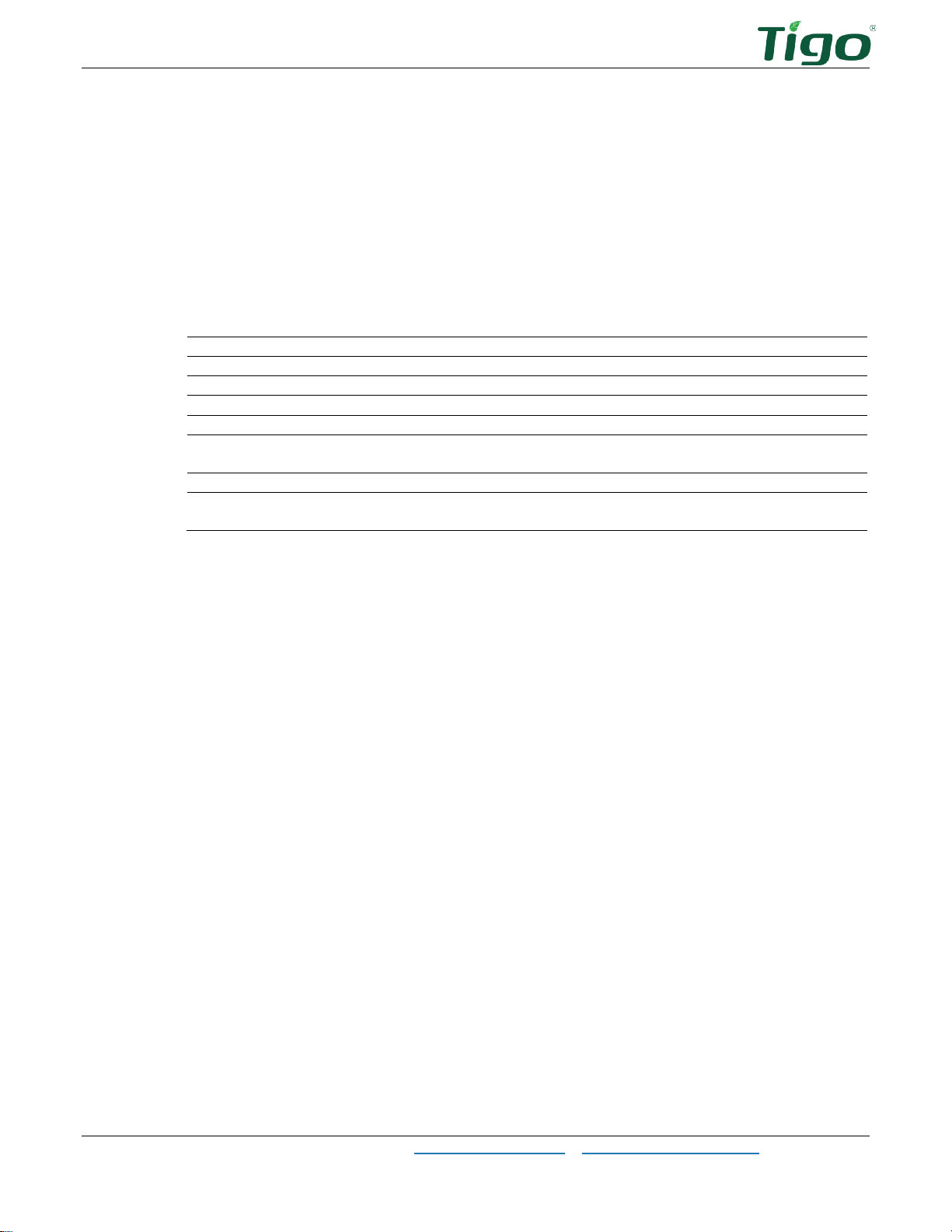
LED
State
Description
Solid green
System OK
The system is operating normally.
Blinking green/gray
SMART app activity
The CCA is connected to the Tigo SMART app.
Blinking green/yellow
User PV-Off
The PV-Off mode was manually activated.
Blinking yellow/gray
Discovery
The CCA is scanning for TAPs/TS4s.
Solid yellow
Warning
Scanning is incomplete or the CCA cannot
connect to the Tigo server.
Blinking red/yellow
Auto PV-Off
The PV-Off mode was automatically activated.
Solid red
Error
CCA cannot find all TS4s or cannot connect to
the Tigo server.
LED Status Indicators
The LED on the right of the CCA indicates system status as well as the status of the
commissioning
Discovery
process:
Use the Tigo Energy Intelligence (EI) app (available in the App Store or Google Play) to
troubleshoot CCA issues.
TS4-A with TAP and CCA Installation Manual | www.tigoenergy.com | [email protected] 10
Page 14
Commissioning
Browser
Mobile App
Commissioning
Perform system configuration and registration with a browser at https://ei.tigoenergy.com or
with the Tigo En er gy Intelligence (EI) mobile app available in the App Store or Google Play.
Final commissioning requires using the Tigo EI mobile app.
• Commercial installers can use a browser to enter the site layout of large numbers of
TS4s and TAPs and then use the Tigo EI app to commission the system.
• Residential installers can use the Tigo EI app for the entire process.
Use a browser or app to:
• Create a Tigo user account.
• Set system information.
• Select equipment.
• Configure equipment and site layout.
• Set system and network access.
Use the mobile app to:
• Connect CCAs to a smartphone or tablet.
• Complete commissioning after all site equipment and TS4 barcodes have been entered.
For detailed instructions how to use either the browser or app, visit the Tigo Ener gy H e l p Center
Commissioning page.
Scan this QR code to download the app.
TS4-A with TAP and CCA Installation Manual | www.tigoenergy.com | [email protected] 11
If you need further help, contact Tigo support within the app or via [email protected].
Page 15
Specifications
Specifications
Download comprehensive specifications for all Tigo products from the Tigoenergy.com
Downloads (www.tigoenergy.com/downloads) page.
Warranty
Download comprehensive warranty information from the Tigoenergy.com Downloads
(www.tigoenergy.com/downloads) page. Con
Support
If you have any questions about installing or maintaining Tigo equipment, visit the Tigo Help
Center, email [email protected], or call:
• North America (7 a.m to 6 p.m. Pacific Time): +1 408 402-0802
• South America (Brazil): +55 21-991045050
• Europe: Phone: +39 055 1987 0059 (Italian, English, German, Polish, Spanish)
• Middle East: Phone: +972 50 687-8618
• Japan: +81 3 4567-6199
• China: +86 512 6587-4600
• Taiwan: +886 919 743-749
• Australia: +61 2 5700 8347
TS4-A with TAP and CCA Installation Manual | www.tigoenergy.com | [email protected] 12
 Loading...