

Page 1
INSTRUCTION MANUAL
INSTRUCTION MANUAL
Electric Version . Flybarless Edition
組裝說明書
組裝說明書
No.4757
This radio control model is not a toy! Before beginning assembly, please read
this manual thoroughly.
本產品為高性能模型非一般玩具,組裝與操作前請詳閱本產品說明書。
The contents are subject to change without prior notice due to product
improvements and specification changes.
本套件所附之零件可能跟圖示有所差異。因產品後續之設計研發或功能不斷改善之原
因,我們將保留產品規格變更權力,不再另行通知使用者。
Page 2
CONTENTS
INTRODUCTION
INTRO & CAUTION / 簡介與注意事項
OTHER ITEMS REQUIRED / 其餘必須配件
MANUAL FORMAT / 說明書使用方式
ASSEMBLY / 組裝步驟
Main Rotor System / 主旋翼機構組裝
Main Rotor Head Linkage Rod Installation / 主旋翼頭連桿組裝
Tail Boom Bracket Assembly / 尾管固定座組裝
Main Frame / 本體組裝
Landing Skid / 腳架組組裝
Main Gear Set / 主齒輪組裝
Control Arm Set / 控制臂組裝
Tail Rotor System / 尾旋翼機構組裝
Tail Unit / 尾部總成組裝
Servo Installation / 伺服機裝配
Linkage Rod Installation / 連桿組裝
Power Motor Installation / 動力馬達安裝
Electric Device Installation / 電子設備配置
Main Rotor Blade / 主旋翼安裝
Electric Version . Flybarless Edition
2
4
5
6
7
8
9
11
12
13
14
16
17
18
19
20
21
SET-UP SECTION / 設定程序說明
Radio System Setup / 遙控系統設定
Swashplate Type Setting / 十字盤模式設定
Electric Device Connection / 電子設備連接說明
Index of Linkage Length / 連桿長度索引
Swashplate & Servo Movement Setting / 十字盤及伺服機動作設定
Tail Control And Gyro Setup / 尾舵控制及陀螺儀控制
Setting Up Data For Your Reference / 參數設定參考
Blade Tracking Adjustment / 主旋翼軌跡調整
Cautions of Li-Po Battery Pack Using / 鋰聚電池使用注意事項
After Flight Checklist / 飛行後的檢查項目
Regular Maintenance / 定期保養事項
SPARE PARTS / 維修零件包
SPARE PARTS LIST / 維修零件包表格
OPTIONAL PARTS / 改裝零件包
OPTIONAL PARTS – FLYBAR EDITION / 改裝零件包-平衡翼旋翼頭
Exploded View / 爆炸圖檢索
22
22
22
23
23
24
25
26
27
27
27
28
32
39
40
41
-1-
Page 3
INTRODUCTION / 簡介
Thank you for purchasing the Thunder Tiger Titan X50 R/C helicopter. This new helicopter is the latest
innovation by Thunder Tiger. It has the perfect combination of flying stability and the agility for 3D flying.
This helicopter is an excellent choice for flying enthusiasts like you. For convenient assembly and safe
operation of the helicopter, please read the instructions carefully. Retain the user manual in case you need
it for any information or reference.
感謝您購買雷虎科技Titan X50直昇機產品,本項產品為雷虎科技全新開發機種,兼具高度穩定性與3D飛行特性,是
熱衷引擎直昇機的您不可錯過的選擇。請於使用本產品前詳盡閱讀使用手冊,以利於組裝工作順暢進行與安全操控本
產品。請妥善保存使用說明書,以利後續調整與維修參考用途。
CAUTION / 警告
1. R/C models are not toys. This product is a high-precision flying machine. Possibilities of unexpected
crashes may occur due to electronic interference, incorrect operation, or poor mechanical maintenance.
Although it is a small-sized helicopter, the rotor blades rotate at high speeds, which may cause serious
damage, injury, or death if the model hits people or property. Therefore, extreme caution must be
exercised during operation.
2. Thunder Tiger ensures parts packaged in this product is of the highest quality. However, after assembly
and usage, parts damaged due to wear or misuse will not be replaced under any circumstances. If you
have any questions regarding its operation and repair, Thunder Tigers service agents are able to
provide free technical guidance.
3. This product is only recommended for users ages 16 and up. Because flying a R/C helicopter is difficult,
beginners must receive guidance and supervision from experienced pilots to minimize unexpected danger.
Practice in spacious areas, far away from obstacles such as buildings, trees, electrical towers, or crowds.
4. To decrease the cost of repair and maintenance for beginners, it is recommended to fly the helicopter
with a practice rack and to learn basic flying skills with a computer R/C flying simulator. (Crashes in
simulators are free to repair!)
1. 本項遙控直昇機產品並不是玩具,是一項結構精密、高專業度模型產品,如果未經正確組裝與操控,將可能對操控
者或其他人造成身體傷害。使用者必須了解,若未確實進行飛行前安全檢查或操控不當,而造成人員受傷或物體損
壞,使用者必須負起法律責任。
2. 本產品由高品質零組件組成,雷虎科技對於安裝過程、使用過後..等人為因素造成損壞事件不負損壞賠償之責。如您
需要本產品相關組裝、調整或其他協助,可與雷虎科技全省經銷商聯繫。
3. 本項產品禁止十六歲以下青少年與孩童使用。強烈建議初學者應取得技術支援後再進行飛行,以避免危險發生。請
於空曠地區操控本產品,並避免於建築物、樹木、電塔..等障礙物區域飛行。
4. 建議初學者可安裝練習架或透過電腦模擬軟體練習,可達到實際練習效果與符合經濟效益。
AMA INFORMATION / 特別注意事項
Operating a model helicopter requires a high degree of responsibility and skill. If you are a newcomer to the
hobby, it is best to seek help and guidance from accomplished model helicopter pilots. This will greatly
speed up the learning process and have you flying successfully in a reasonable amount of time. We also
would strongly urge you to join the Academy of Model Aeronautics. The AMA is a non-profit organization
that provides its members with a liability insurance plan as well as monthly magazine entitled Model Aviation.
All AMA charter aircraft clubs require all pilots to hold a current AMA sporting license prior to operation of
their models at club fields. For further information, contact the AMA at:
Academy of Model Aeronautics
5151 East Memorial Drive
Muncie, IN 47302
(317) 287-1256
操控遙控直昇機對於飛行安全要求極高,需要高度的負責任態度配合,以及較高的操控技巧。如果您是一位初學者,
建議您必須向當地專業模型經銷商,或是遙控直昇機相關組織以及經驗豐富的玩家尋求相關協助,以獲得您所需要的
訊息以及專業知識。如此可有效協助您縮短學習的時間,更容易學會遙控直昇機的組裝、設定與操控技巧。
-2-
Page 4
FLIGHT SAFETY CHECKLIST / 飛行前安全確認工作項目
1. Make sure that the transmitter battery is fully charged before flying.
2. Make sure all control surfaces are operated properly before flying.
3. Do a range check of the radio before the first flight. The electronic equipment must operate properly
at a range of at least 5 meters (18 ft) even with the transmitter antenna collapsed.
4. Make sure there are no other pilots using the same radio frequency with yours and that there are no
other radio interference on your frequency.
5.
Be sure to turn on the transmitter first with the throttle stick in the idle position. Plug the battery into the
ESC last.
6. The main rotor and the tail rotor spin at very high RPM. Make sure nothing can come in contact with
the rotor blades during flight.
7. Always maintain a safe distance from the helicopter during flight.
8. Never fly the helicopter in the rain or in excessive wind conditions.
9. Always operate and fly the helicopter in a safe and responsible manner.
10. Never fly the helicopter over other pilots, spectators, cars or anything that could result in injury or
property damage.
1. 確認接收機與發射機電池,均已確實充電完成。
2. 確認所有操控介面運作順暢。
3. 確認無其他無線電波干擾,且不與其他同好同時使用相同頻率。
4. 確實將油門搖桿放置於低速,再將發射機電源開啟,然後再將電池接上。
5.
確認遙控器發射器與接收機工作正常,將機體放至於距離5公尺外,確認遙控器是否正常,機體控制動作是否正確。
6. 主旋翼與尾旋翼轉速相當高,運轉時須避免任何障礙物與旋翼接觸。
7. 飛行時,需與遙控直升機保持安全距離。
8. 勿於下雨天或是強風的狀態下操控遙控直升機。
9. 請以安全為第一考量,並以高度負責任的態度參與遙控直升機活動。
10. 禁止於人群、車輛..或任何其他障礙物上方飛行遙控直升機,避免意外發生。
POST FLIGHT INSPECTION / 飛行結束安全檢查事項
1. Inspect the model thoroughly to insure no parts have come loose or become damaged during the flight
and landing. Replace damaged parts and tighten loose screws before flying again.
2. Clean the helicopter body.
3. Lubricate all moving parts to ensure smooth operation for the next flying.
4. Replace any worn ball links and damaged bearings.
5. Store the model in a cool, dry place. Avoid putting it under direct sunlight or near a source of heat.
Following these simple rules will allow you to enjoy the thrill of model helicopter flying for many years.
1. 飛行結束後確認機體所有的零件與螺絲是否有損壞或鬆動,更換損壞零件與確實固定鬆動的螺絲。
2. 機體清潔乾淨。
3. 檢查所有活動零組件是否運作順暢,以利下次飛行。
4. 更換所有鬆動的連桿、接頭,以及損壞的軸承。
5. 將機體存放於陰涼通風處,避免機體放置於陽光直射處或接近熱源。
確實執行上述幾項簡單的步驟,將可確保您的愛機維持數年的壽命!
CAUTION / 注意事項
When the model has crashed, inspect the flybar, rotor shaft and the blade spindle to make sure they are
not bent. If any item is damaged, it must be replaced with a new part to ensure safe operation. Do not
glue any broken or damaged plastic parts. Do not repair broken rotor blades. It is very important to
inspect the motor, speed control and the battery.
Always inspect the following items:
Gears, Ball links, Link rods, Bearings, Main shaft, Flybar, Spindle, Tail boom and support, Fins, Tail rotor
shaft, Belt, Main blades, Tail blades, the Motor, the Speed control and the Battery.
機體一但發生墜落事件,請確實檢查平衡桿、主軸、橫軸是否有彎曲變形,如果有任何的損壞,請立即更換原廠新
的零組件,確認機體操作安全!切勿使用任何接著劑嘗試黏合塑膠零件;請勿使用修復過的主旋翼。馬達、速控器
、電池的安全檢查工作亦相當重要。
發生機體墜落事件後,請確實檢查下列項目:
齒輪組、球頭連桿、連桿頭、軸承、主軸、橫軸、尾軸、平衡桿、平衡片、尾管、尾管支撐架、垂直與水平尾翼、
尾驅動輪、皮帶、主旋翼、尾旋翼、馬達、速控器、電池。
-3-
Page 5
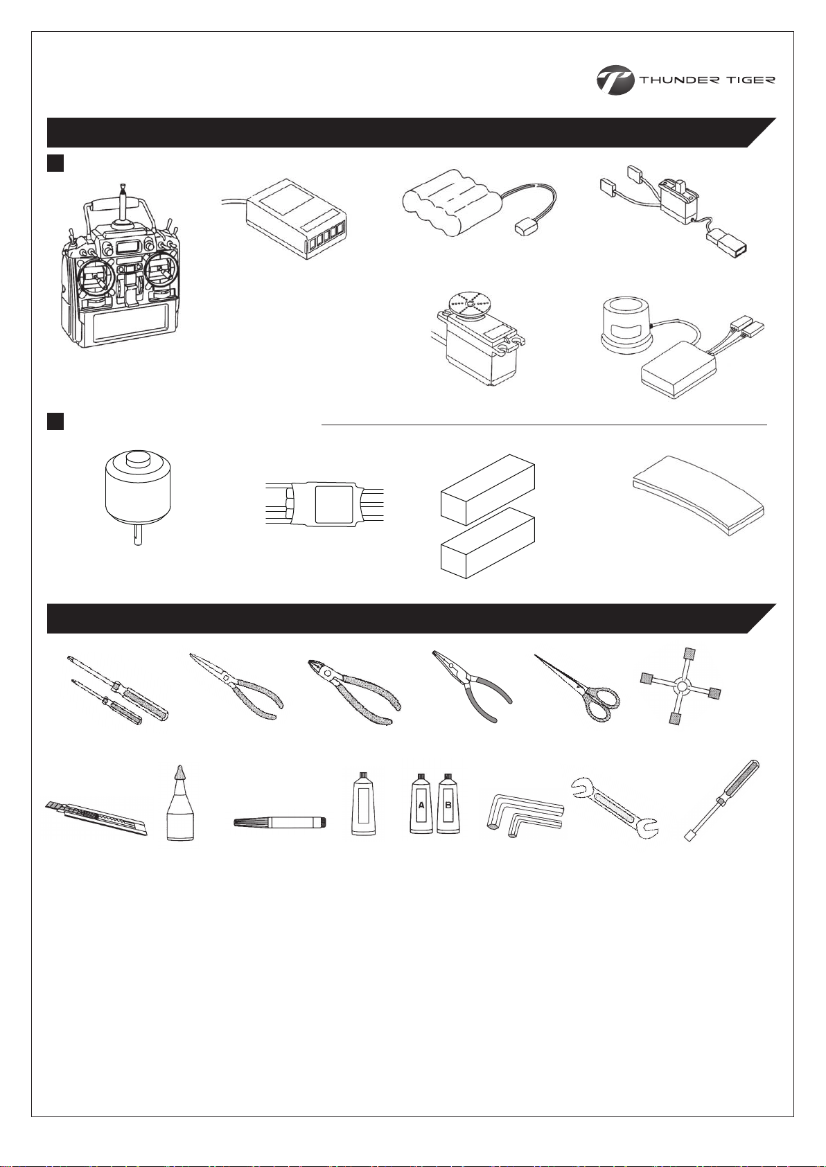
OTHER ITEMS REQUIRED 需自行準備的配件
RADIO SET / 遙控系統
Receiver
接收機
Transmitter (helicopter type
only, 6 or more channels)
發射機(需具備直昇機控制功能
的6動以上遙控器)
Battery 接收機電池
1000mAh
Servo
伺服機
Switch Harness
具備充電線的開關組
Gyro
陀螺儀
POWER SYSTEM / 動力系統
Electric Brushless Motor
無刷馬達
Electronic Speed Controller
速控器
8~12S Li-Po Battery Pack
鋰聚電池組
TOOLS REQUIRED FOR ASSEMBLY 需要準備的工具
Foam
雙面膠帶
Screw Driver
各種規格的螺絲起子
Hobby Knife
美工刀
C.A Glue
瞬間膠
Needle Nose Pliers
尖嘴鉗
Threadlocker
螺絲防鬆膠
Nipper
斜口鉗
Grease
潤滑油
Ball Link Pliers
拆連桿頭的專用鉗子
Epoxy
環氧樹酯
Hex Wrench
六角板手
Scissors
剪刀
5.5mm
Metric 4-way Wrench
十字套筒板手
7mm
Wrench
開口板手
Socket Drivers
套筒螺絲起子
5.5mm
7mm
8mm
5.5mm
7mm
8mm
10mm
-4-
Page 6
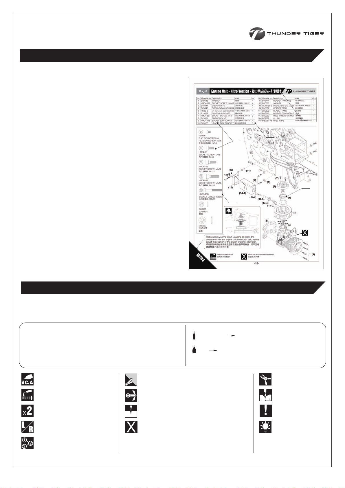
MANUAL FORMAT / 說明書使用方式
How to read the instruction manual?
說明書導讀
A: Indicates the assembly step number and the parts bags
that are to be assembled.
B: Displays actual size drawings, and part quantities used.
C: All parts, except screws, are identified by its order
numbers. When purchasing spare parts, identify the part
required and cross reference this to the spare parts list in
the end of this maunal, which shows the purchasable
spare parts and the corresponding order numbers.
D: This instruction manual uses several symbols. Pay careful
attention to them during construction. Details are given
at the bottom of each page.
E: If a label marked here indicates the page is the exclusive
assembly steps for a particular model type; please follow
the exclusive instructions according to the model type you
purchased.
A: 顯示組立步驟及需組立之零件包順序。
B: 零件實際對照尺寸及使用數量。
C: 請比對零件形狀以及後附零件料號對照圖示找出需求零件料號。
D: 操作說明符號可更有效協助組裝者使用此說明書,請依說明書符
號指示進行組裝步驟。
E: 出現此標籤表示本頁為特定模型版本之專屬組裝說明,請依您所
購買之版本依說明進行組裝步驟。
Example 說明範例
E
B
C
D
A
B
C
SYMBOLS USED THROUGHOUT THE MANUAL / 符號說明
The parts in the KIT are packed according to each major assembly steps. The part number and quantity are always
shown in the square box on each page. As good practice, only open up the bag that you need for the paticular assembly.
零件均依照組裝步驟包裝,請依照組裝程序,逐一開啟零件包,避免零件遺失。
Note / 注意
Assembly drawings will contain icons that indicate use of
Threadlocker or CA glue as needed.
Examples of the icons are as right shown:
請依組裝步驟圖示,使用防鬆膠或接著劑。
圖示範例如右:
Apply C.A Glue
使用快乾膠黏合
Apply threadlocker
使用螺絲防鬆膠
Assemble as many times as specified
依指示組裝所需數量
Assemble left and right side the same way
左右側組件相同
Assemble in right order
依標示順序組裝
Cut off shaded portion
依標示部分裁切
Ensure smooth, non-binding movement when assembling
確認組件靈活度
Drill holes with the specified diameter
依標示尺寸鑽孔
Must be purchased separately
改裝品需另購
T22(#262) THREADLOCKER / 螺絲防鬆膠
CA CA GLUE / 快乾膠
Cut off excess
裁剪多餘部分
Apply grease
使用潤滑油膏(黃油)
Pay close attention here
注意組裝步驟
Hint
組裝提示
-5-
Page 7
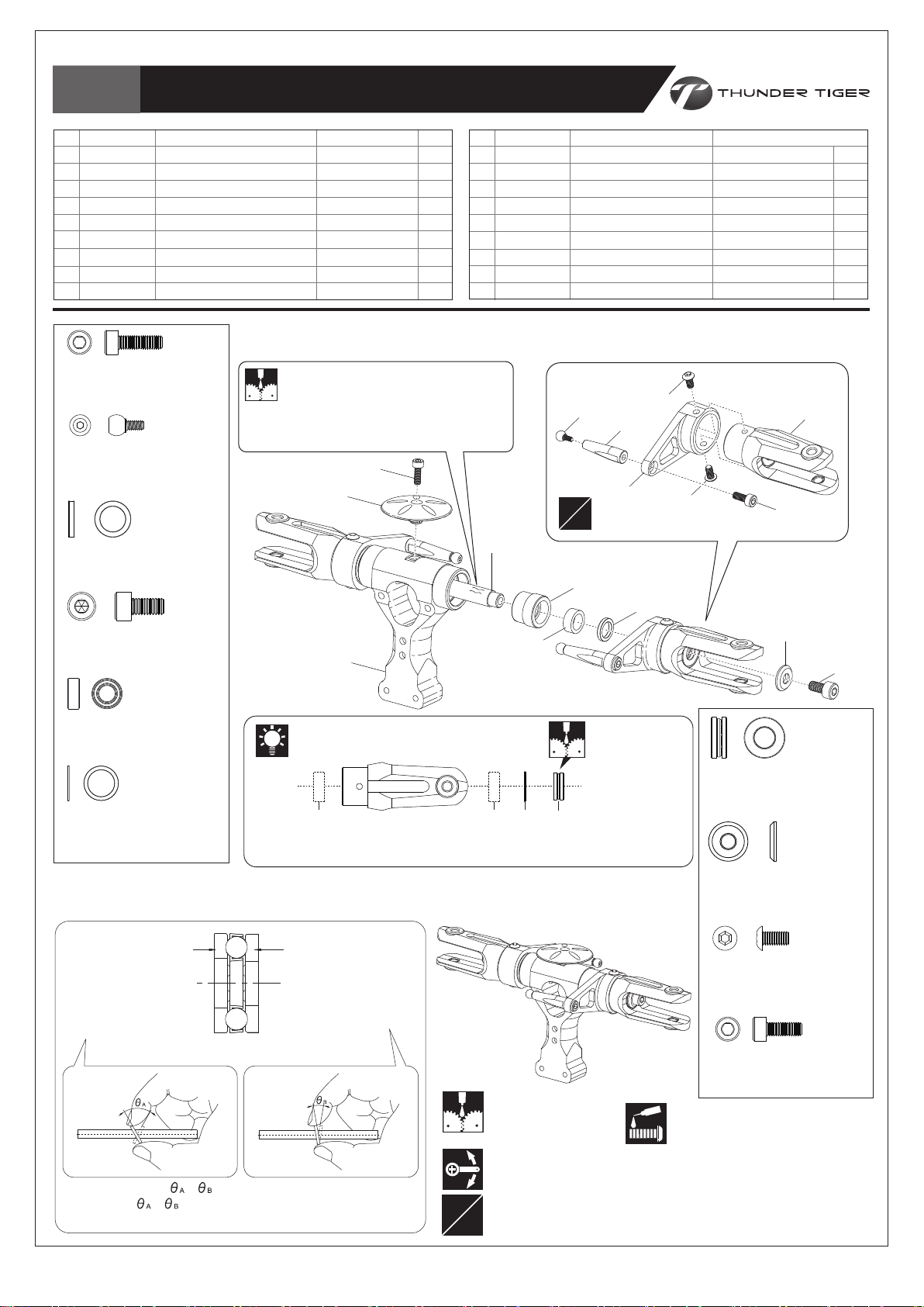
Bag A
Main Rotor System / 主旋翼機構組裝
Material No. Description
No.
1
BV2574
BK2575
2
BK2576
3
HMC3-8B
4
BK0649-1
5
HSA3-6
6
BK2216
7
HMX0612
8
BK2214
9
HMC3-10B
SOCKET SCREW,M3x10
內六角螺絲,M3x10
BK0649-1
LINKAGE BALL(A)
內六角連接頭螺絲(A)
BK2525
FLAP COLLAR,d7xD10xW1.5
避震軸環,d7xD10xW1.5
METAL MAIN ROTOR GRIP SET
FL METAL ROTOR GRIP LEVER
FL METAL ROTOR GRIP POST
SOCKET SCREW, M3×8
LINKAGE BALL(A)
BUTTON HEAD SOCKET SCREW, M3X6
THRUST WASHER, d10xD13xW0.5
THRUST BEARING,d6xD12xW4.5
HARDENED FEATHERING SHAFT
名稱
金屬旋翼轉座組
無平衡翼金屬轉座擺臂
無平衡翼金屬連接座
內六角螺絲, M3×8
內六角連接頭螺絲(A)
半圓頭內六角螺絲, M3x6
止推墊片, d10xD13xW0.5
止推軸承,d6xD12xW4.5
強化固定軸(D7)
Qty
2
2
2
2
2
4
2
2
1
No.
10
BK2573
11
BK2572
12
BK2525
13
BK0435
14
HMC4-8B
15
HMV1370ZZWY
16
BK2510
17
BK2182
18
HMC25-8B
OUTER DAMPER, 7mm
INNER DAMPER, 7mm
FLAP COLLAR, d7xD10xW1.5
WASHER, d4xD11xW1.7
SOCKET SCREW, M4×8
BEARING, d7xD13xW5
METAL MAIN ROTOR HUB
METAL HEAD BUTTON
SOCKET SCREW, M2.5×8
Secure all screws shown on this page with a drop of thredlocker.
本頁顯示之螺絲請使用適量防鬆膠鎖固。
Apply some amount of silicon oil or
Vaseline on the Spindle for easy
assembly.
在橫軸上塗抹此許矽膠油脂或凡士林可
使組裝更為容易。
(5)
(6)
(3)
(18)
(17)
(2)
L
R
(9)
(10)
(12)
(6)
名稱
外避震墊圈, 7mm
內避震墊圈,7mm
避震軸環, d7xD10xW1.5
墊圈, d4xD11xW1.7
內六角螺絲, M4×8
滾珠軸承, d7xD13xW5
金屬主旋翼固定座
金屬旋翼頭制動器
內六角螺絲, M2.5×8
(1)
(4)
QtyMaterial No. Description
2
2
2
2
2
4
1
1
1
HMC4-8B
SOCKET SCREW M4×8
內六角螺絲M4×8
HMV1370ZZWY
BEARING,d7xD13xW5
滾珠軸承,d7xD13xW5
BK2216
THRUST WASHER,d10xD13xW0.5
止推墊片,d10xD13xW0.5
The bearings (#15) come with the grips which had been assembled by Factory.
主旋翼夾座內軸承
(16)
Assemble the main rotor pitch housing as drawing
主旋翼轉座組裝示意圖
Diagram for Thrust Bearing Assembly
止推軸承安裝示意圖
Large Internal
Diameter
always go toward the
Main Rotor Hub
內徑較大的一側,面向
主旋翼中心座組。(內
側)
Small Internal
Diameter
always go toward the
Blade
內徑較小的一側,面向
主旋翼組(外側)。
(#15)
已由原廠壓配完成。
(11)
(8)
(7)(15)(15)
Completed View
組裝完成
(13)
(14)
HMX0612
THRUST BEARING,d6xD12xW4.5
止推軸承,d6xD12xW4.5
BK0435
WASHER,d4xD11xW1.7
墊圈,d4xD11xW1.7
HSA3-6
BUTTON HEAD SOCKET SCREW,M3x6
半圓頭內六角螺絲,M3x6
HMC25-8B
SOCKET SCREW,M2.5x8
內六角螺絲,M2.5x8
Checking Tips: >
轉動角度: >
(轉動角度大者,內孔大;轉動角度小者,內孔小)
Apply grease
使用潤滑油膏(黃油)
Ensure smooth, non-binding movement when assembling
確認組件靈活度
Assemble left and right side the same way
L
左右側組件相同
R
Apply threadlocker
使用螺絲防鬆膠
-6-
Page 8
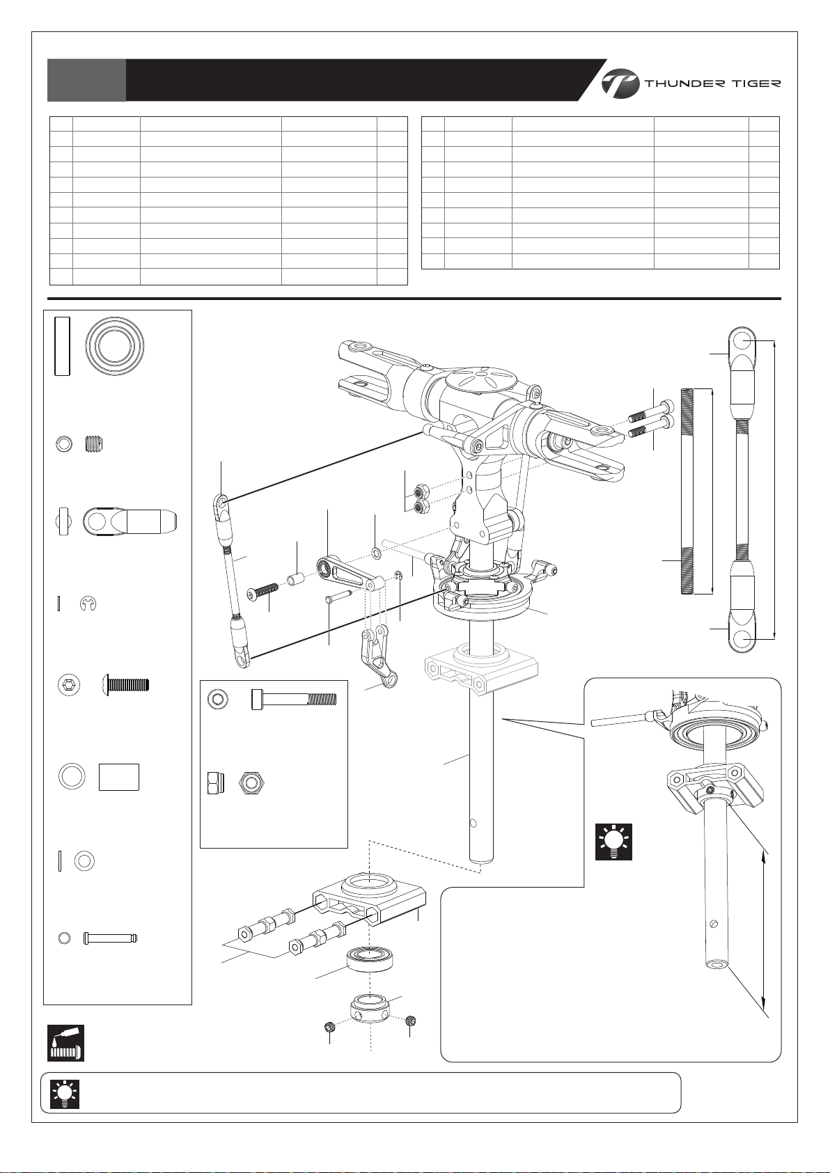
Bag A
Main Rotor Head Linkage Rod Installation / 主旋翼頭連桿組裝
No.
1
BK2236
2
BK2219
3
HMV6800ZZY
4
BK2206
5
HME4-3B
6
BK2596
7
BK1925
8
HSA3-14
9
BK0077
10
BV2508
HMV6800ZZY
BEARING,d10xD19xW5
滾珠軸承,d10xD19xW5
HME4-3B
SET SCREW,M4x3
無頭內六角螺絲,M4x3
Description
UPPER BRG
FRAME SPACER
BEARING, d10xD19xW5
MAIN SHAFT LOCK RING
SET SCREW, M4x3
LINKAGE ROD, 52L
BALL LINK
BUTTON HEAD SOCKET SCREW, M3x14
COLLAR, d3xD4xW6
FB Metal CONTROL LEVER SET
名稱
上軸承座
六角連接支柱
滾珠軸承, d10xD19xW5
止檔圈
無頭內六角螺絲, M4x3
連接桿, 52L
單頭連接桿
半圓頭內六角螺絲, M3x14
軸環, d3xD4xW6
無平衡翼金屬控制搖臂組
QtyMaterial No.
1
2
1
1
2
2
4
2
2
2
No.
11
12
13
14
15
16
17
18
19
BK0088
BK0171
HMS15
BK0016-1
BK0616
HMM3Z
BV2188A
BK2209
BK2277
Description
WASHER, d3xD5xW0.5
PIN
E RING
WASHOUT LINKAGE
SOCKET SCREW, M3x20
NYLON NUT, M3
METAL SWASHPLATE
SWASHPLATE CONTROL ROD
HARDENED MAIN SHAFT
Secure all screws shown on this page with a drop of thredlocker.
本頁顯示之螺絲請使用適量防鬆膠鎖固。
(7)
(10)
(16)
(11)
名稱
墊片, d3xD5xW0.5
插銷
E型扣環
連接座
內六角螺絲(半牙), M3x20
止鬆螺帽,M3
金屬十字盤組
十字盤穩定桿
強化主軸
Scale=1:1 (unit:mm)
(7)
(15)
(15)
40
QtyMaterial No.
2
2
2
2
2
2
1
1
1
76
BK1925
BALL LINK
單頭連接桿
HMS15
E RING
E型扣環
HSA3-14
BUTTON HEAD SOCKET SCREW,M3x14
半圓頭內六角螺絲,M3x14
BK0077
COLLAR,d3xD4xW6
軸環,d3xD4xW6
BK0088
WASHER,d3xD5xW0.5
墊片,d3xD5xW0.5
BK0171
PIN
插銷
Apply threadlocker
使用螺絲防鬆膠
(9)
(6)
(A)
(8)
BK0616
SOCKET SCREW, M3x20
內六角螺絲(半牙), M3x20
HMM3Z
NYLON NUT, M3
止鬆螺帽, M3
(2)
(3)
(12)
(5)
(14)
(18)
(13)
(4)
(5)
(1)
(19)
(6)
(17)
The distance
form the Lock
Ring to the end of the Main Shaft is
about 95.0 mm.
The actual position may need to be
adjusted after mounting the head into
the frames to eliminate the play,
therefore, do not secure the screw #5
tightly at this step.
主軸末端至止擋圈距離約為95.0 公釐。
當旋翼頭安裝至側板時,實際位置可能需調
整,此步驟可暫不鎖緊螺絲#5。
(7)
(A)x2
95mm
The length may vary when using different servos, please re-adjust the length as actual condition.
搭配不同品牌伺服機時,連桿長度或有不同,調機時,請再依實際狀況進行微調。
-7-
Page 9
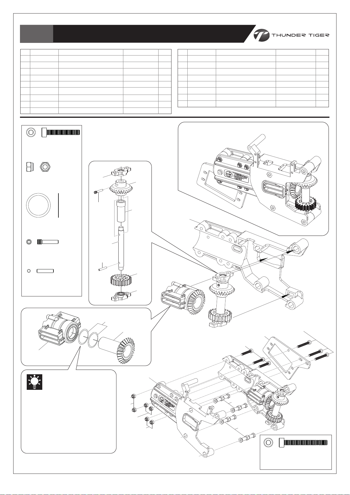
Bag B
Tail Boom Bracket Assembly /
尾管固定座組裝
No.
1
BK2531
2
BK2532
3
BK2219
4
HMC3-20B
5
HMM3Z
6
BV2269
7
BK2268
8
BK2509
9
BV2265
HMC3-20B
SOCKET SCREW,M3x20
內六角螺絲,M3x20
HMM3Z
NYLON NUT,M3
止鬆螺帽,M3
BK2509
WASHER, d12xD14.5xW0.2
墊片, d12xD14.5xW0.2
TAIL BOOM BRACKET-L
TAIL BOOM BRACKET-R
FRAME SPACER
SOCKET SCREW, M3x20
NYLON NUT, M3
TAIL GEAR MOUNT SET
TAIL GEAR-B
WASHER, d12xD14.5xW0.2
BEARING BLOCK SET
名稱
尾管固定座(左)
尾管固定座(右)
六角連接支柱
內六角螺絲, M3x20
止鬆螺帽, M3
傘齒輪固定座組
傘齒輪B-25T
墊片, d12xD14.5xW0.2
軸傳軸承座組
QtyMaterial No. Description
1
1
4
3
6
1
1
2
2
Assemble the Tail Boom Bracket
as drawing. Secure the Screws
but do not tighten at this step.
參考圖示組裝尾管固定座,螺絲只需
稍事固定,暫無需鎖緊。
(9)
(14)
(11)
(13)
No.
10
11
12
13
14
15
16
17
BK2583
BK2267
BK2506
BK2554
BD7143
HMY2-12
BK0539-1
HMC3-25B
Description
TAIL DRIVE GEAR-22T
TAIL GEAR-A
TAIL DRIVE GEAR SHAFT
COLLAR
FIXED SCREW
PIN, d2x12
SERVO MOUNT
SOCKET SCREW, M3x25
Completed View
組裝完成
(1)
名稱
軸傳尾驅動輪-22T
傘齒輪 A-25T
軸傳驅動軸
軸套
傳動軸固定螺絲(長)
軸承滾針, d2x12
伺服機固定板
內六角螺絲, M3x25
QtyMaterial No.
1
1
1
1
1
1
1
3
BD7143
FIXED SCREW
傳動軸固定螺絲(長)
HMY2-12
PIN, d2x12
軸承滾針, d2x12
(15)
(8)
(6)
Check the mesh of Gears (#7&
#10) after this step accomplished,
if the mesh is too much play, please
add the Washers (#8) to eliminate
the play for a proper mesh.
完成尾管固定座組裝步驗後,請檢查齒
輪間隙 (#7& #10) ,若間隙過大,請
加裝所附墊片 (#8) 進行調整,以獲得
適當的齒輪間隙。
(12)
(7)
(5)
(5)
(10)
(9)
(2)
(5)
(3)
(4)
(3)
(16)
HMC3-25B
SOCKET SCREW,M3x25
內六角螺絲,M3x25
(17)
-8-
Page 10
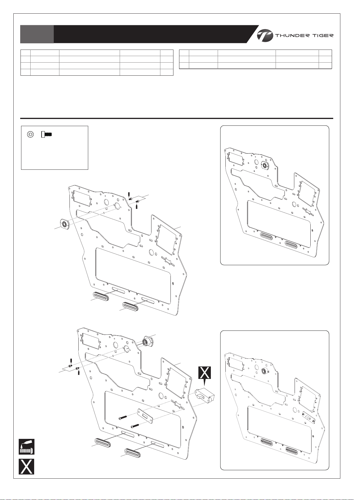
Bag C+D
Main Frame /
本體組裝
No.
1
BK2255
2
HMC2-4B
3
BK2551
HMC2-4B
內六角螺絲,M2x4
SOCKET SCREW,M2x4
SIDE FRAME
SOCKET SCREW,M2x4
RUBBER GROMMETS
Left Frame / 左側板
名稱
機身側板
內六角螺絲,M2x4
橡膠墊圈
(2)
QtyMaterial No. Description
No.
4
2
4
4
5
BV2238
BV2237
ELEVATOR WASHER MOUNT SET(L)
ELEVATOR WASHER MOUNT SET(R)
名稱
升降舵墊片座組(左)
升降舵墊片座組(右)
QtyMaterial No. Description
1
1
Completed View
組裝完成
(4)
(3)
Right Frame / 右側板
(2)
(1)
(3)
(5)
Completed View
組裝完成
(1)
Apply threadlocker
使用螺絲防鬆膠
Must be purchased separately
改裝品需另購
(3)
(3)
-9-
Page 11
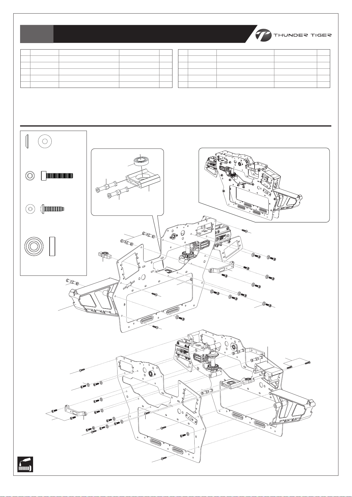
Bag D
Main Frame / 本體組裝
No.
1
BK2225
2
HMV6800ZZY
3
BK2219
4
BV2262
5
BK2270
BK0087
WASHER,d3xD8xW1.4
墊片,d3xD8xW1.4
HMC3-10B
SOCKET SCREW,M3x10
內六角螺絲,M3x10
HNX3-12B
S.B.H SELF TAPPING SCREW
半圓頭內六角自攻螺絲
LOWER BRG
BEARING, d10xD19xW5
FRAME SPACER
LOWER MOTOR MOUNT SET
RECEIVER TRAY
名稱
下軸承座
滾珠軸承, d10xD19xW5
六角連接支柱
馬達下座組
接收機座
QtyMaterial No. Description
No.
6
1
1
6
1
1
BK2273
7
HNX3-12B
8
HMC3-10B
9
BK0087
10
BK2259
CONTROL ARM TRAY
S.B.H SELF TAPPING SCREW
SOCKET SCREW,M3x10
WASHER,d3xD8xW1.4
SERVO FRAME B
Secure all screws shown on this page with a drop of thredlocker
除螺絲#7之外,本頁顯示之螺絲請使用適量防鬆膠鎖固。
(2)
(3)
(1)
(3)
(3)
名稱
控制搖臂座
半圓頭內六角自攻螺絲
內六角螺絲, M3x10
墊片, d3xD8xW1.4
伺服機座B
except the screws #7.
Completed View
組裝完成
(7)
QtyMaterial No. Description
2
10
22
18
1
HMC6800ZZY
BEARING, d10xD19xW5
滾珠軸承, d10xD19xW5
(3)
(5)
(7)
(8)
(8)
(7)
(9)
(6)
(4)
(7)
(7)
(7)
(7)
(3)
(3)
(3)
(6)
(9)
(8)
(10)
(7)
Apply threadlocker
使用螺絲防鬆膠
(7)
-10-
Page 12
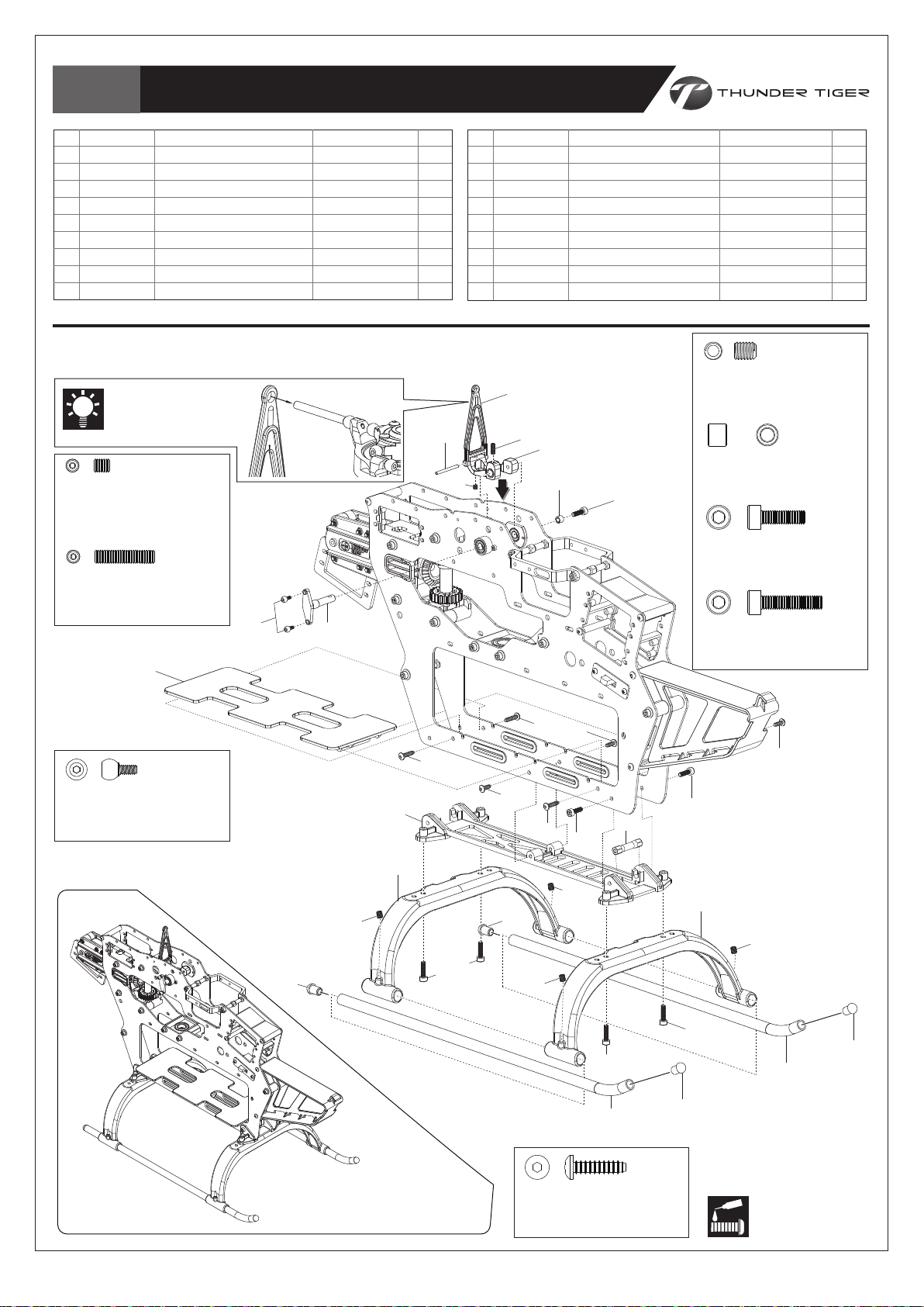
Bag E
Landing Skid /
腳架組組裝
No.
1
2
3
4
5
6
7
8
9
BK0023
BK0084
BK2514
HME3-3B
HME3-8B
BK2571
BK0649-1
BK2515
HMC3-10B
名稱
ELEVATOR CONTROL ARM LINK
PIN
,D2x22.8
METAL ELEVATOR CONTROL ARM
SET SCREW.M3x3
SET SCREW,M3x8
FL ELEVATOR LEVER ROD, 4757
LINKAGE BALL(A)
COLLAR,d3xD5xW4.2
SOCKET SCREW,M3x10
升降舵連接座
固定銷,D2x22.8
金屬升降舵控制臂
無頭內六角螺絲,M3x3
無頭內六角螺絲,M3x8
無平衡翼升降舵推拉桿, 4757
內六角連接頭螺絲(A)
控制臂軸環,d3xD5xW4.2
內六角螺絲,M3x10
QtyMaterial No. Description
No.
10
1
1
1
1
1
1
2
1
3
BK2261
11
BK0064T
12
BK0065
13
HME4-5B
14
HMC3-14B
15
BK2258
16
BK2274
17
BK2253
18
HNX3-12B
LANDING SKID
SKID PIPE
SKID PIPE END CAP
SET SCREW,M4x5
SOCKET SCREW,M3x14
BOTTOM FRAME
BATTERY TRAY
FRAME SPACER
S.B.H SELF TAPPING SCREW
Secure all screws shown on this page with a drop of thredlocker except the screws #13, 14 & 18.
除螺絲#13, 14及18之外,本頁顯示之螺絲請使用適量防鬆膠鎖固。
The larger hole goes toward
(1)
the swashplate.
較大孔面朝十字盤
HME3-3B
SET SCREW.M3x3
無頭內六角螺絲,M3x3
HME3-8B
SET SCREW,M3x8
無頭內六角螺絲,M3x8
(7)
(6)
(2)
(4)
(5)
(3)
(8)
(9)
(16)
名稱
腳架
底座圓管
圓管塞
無頭內六角螺絲,M4x5
內六角螺絲,M3x14
底盤
電池座
六角支柱
半圓頭內六角自攻螺絲
HME4-5B
SET SCREW,M4x5
無頭內六角螺絲,M4x5
BK2515
COLLAR,d3xD5xW4.2
控制臂軸環,d3xD5xW4.2
HMC3-10B
SOCKET SCREW,M3x10
內六角螺絲,M3x10
HMC3-14B
SOCKET SCREW,M3x14
內六角螺絲,M3x14
QtyMaterial No. Description
2
2
4
4
4
1
1
1
6
BK0649-1
LINKAGE BALL(A)
內六角連接頭螺絲(A)
(12)
(13)
(15)
(10)
(18)
(14)
(18)
(12)
(13)
(18)
(18)
(18)
(9)
(13)
(14)
(11)
(18)
(9)
(17)
(10)
(13)
(14)
(12)
(11)
(12)
Completed View
組裝完成
-11-
HNX3-12B
S.B.H SELF TAPPING SCREW
半圓頭內六角自攻螺絲
Apply threadlocker
使用螺絲防鬆膠
Page 13
Bag F
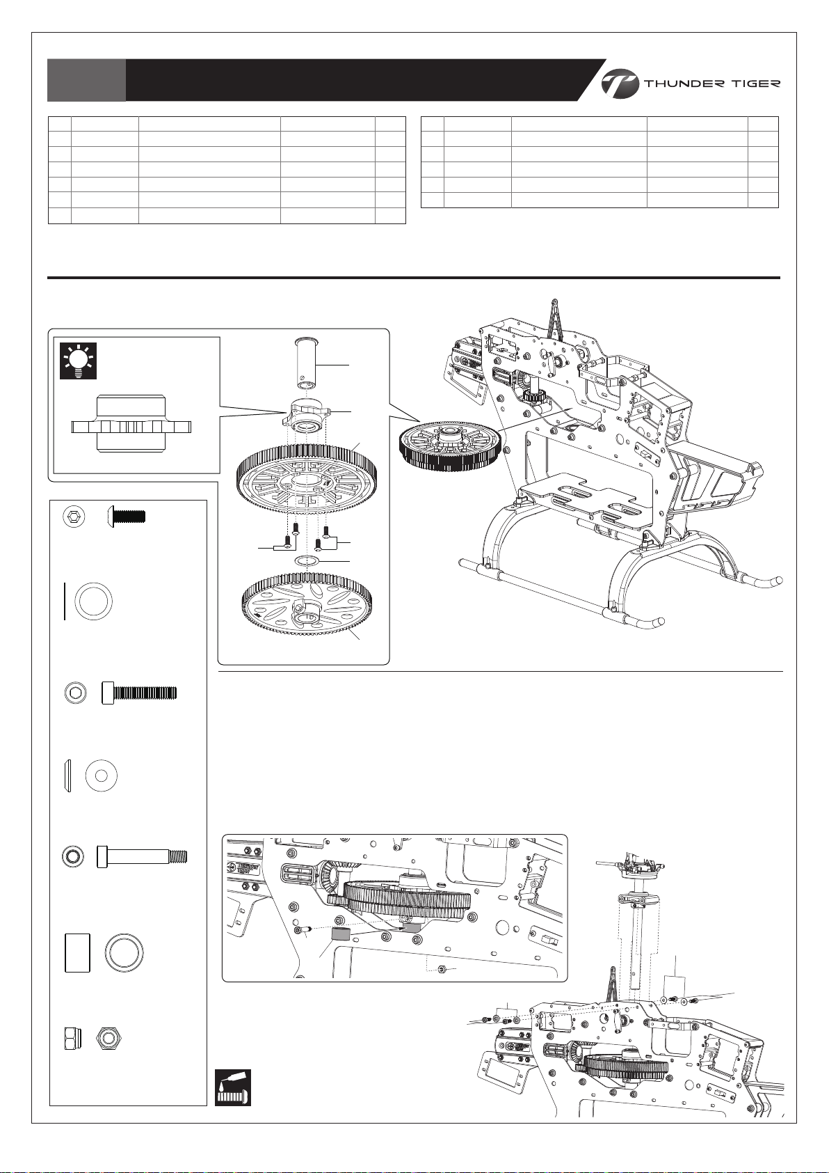
Main Gear Set /
主齒輪組裝
No.
1
2
3
4
5
6
BK2282
BV2281
BK2581
HSA3-8
BK2524
BK2582
ONE WAY BEARING SHAFT
ONE WAY CLUTCH HOUSING
MAIN GEAR, 135T
BUTTON HEAD SOCKET SCREW,M3x8
MAIN GEAR WASHER
AUTOROTATION TAIL DRIVE PULLEY,100T
名稱
單向軸套
單向離合組
主齒輪, 135T
半圓頭內六角螺絲,M3x8
主齒輪墊片
軸傳尾驅動主齒,100T
QtyMaterial No. Description
No.
1
1
1
10
4
11
1
1
Secure all screws shown on this page with a drop of thredlocker.
本頁顯示之螺絲請使用適量防鬆膠鎖固。
Note the chamfer
should point up.
(1)
注意有倒角端朝上
(2)
(3)
BV2281
7
HMC3-10B
8
BK0087
9
BK1197
BK2290
HMM3Z
SOCKET SCREW,M3x10
WASHER,d3xD8xW1.4
MAIN SHAFT BOLT,M3x20
COLLAR
NYLON NUT,M3
名稱
內六角螺絲,M3x10
墊片,d3xD8xW1.4
內六角半牙螺絲,M3x20
軸環
止鬆螺帽,M3
QtyMaterial No. Description
4
4
1
1
1
HSA3-8
BUTTON HEAD SOCKET SCREW,M3x8
半圓頭內六角螺絲,M3x8
BK2524
MAIN GEAR WASHER,d14.2xD19xW0.5
主齒輪墊片,d14.2xD19xW0.5
1. Insert the Main Shaft into Main Gear Set, Main Gear Washer & Lower Bearing Block.
2. Line up the holes of the Autorotation Tail Drive Gear, One Way Bearing Shaft & Main
HMC3-10B
SOCKET SCREW,M3x10
內六角螺絲,M3x10
3. Adjust the position of Lock Ring to eliminate play of the Main Shaft, and then secure the
1. 將主軸依序穿過主齒輪組、主齒輪墊片及下軸承座。
BK0087
WASHER,d3xD8xW1.4
墊片,d3xD8xW1.4
BK1197
MAIN SHAFT BOLT,M3x20
內六角半牙螺絲,M3x20
2. 對正尾驅動齒、單向軸套及主軸上孔位後,穿入內六角螺絲並加上螺帽,並使用適量防鬆劑固定。
3. 調整止擋環位置以消除主軸間隙後,著以適量防鬆膠鎖固。
(4)
(4)
(5)
(6)
Shaft, and then insert the Socket Screw to fix them with a Nut. Add a drop of threadlocker
when securing, but do not over tighten.
set screws tightly with a drop of threadlock.
注意! 請勿過度緊迫螺絲。
BK2290
COLLAR,d10xD14xW9
軸環,d10xD14xW9
HMM3Z
NYLON NUT,M3
止鬆螺帽,M3
(9)
(10)
Apply threadlocker
使用螺絲防鬆膠
-12-
(7)
(11)
(8)
(8)
(7)
Page 14
Bag F+I
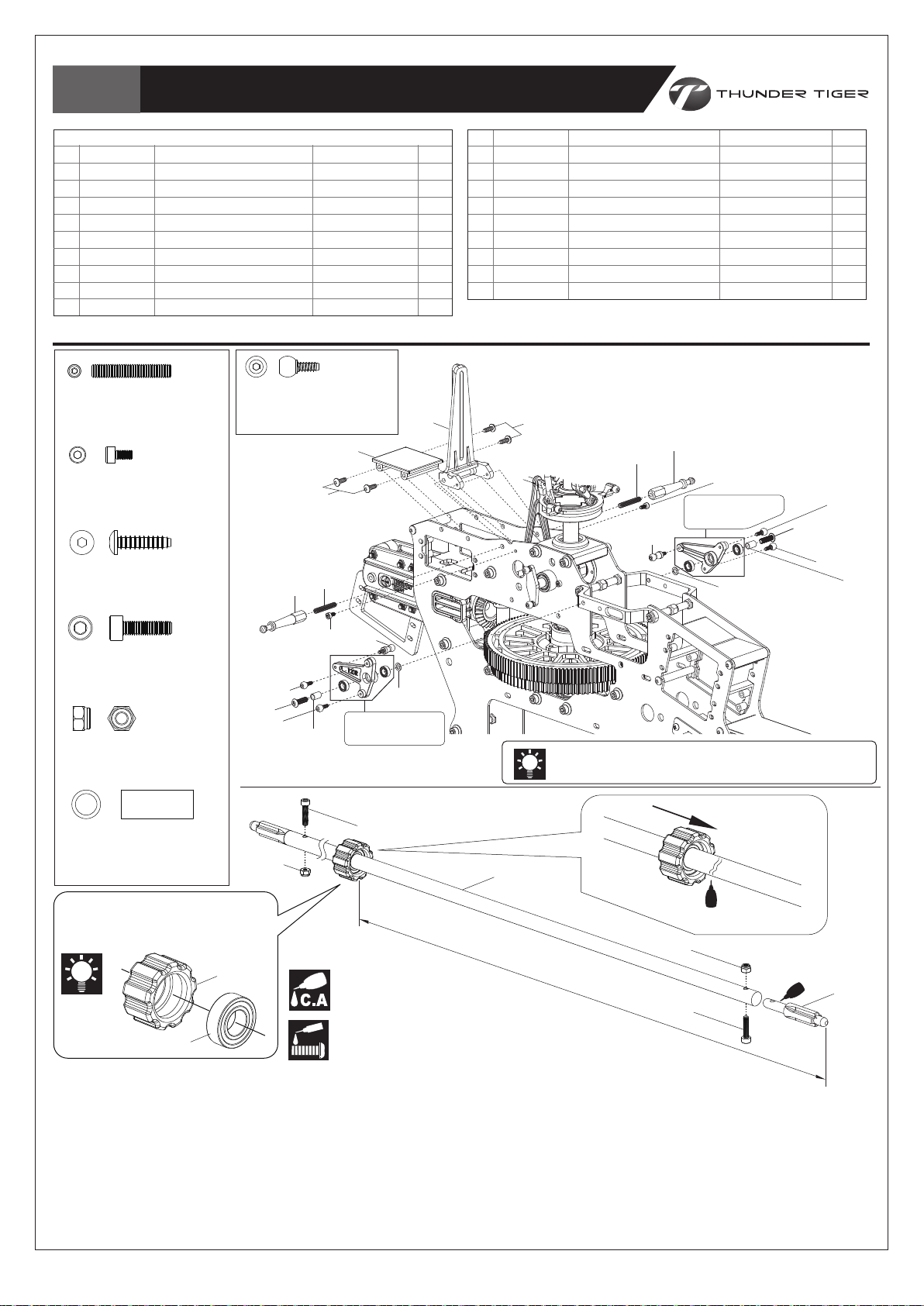
Control Arm Set /
控制臂組裝
No.
1
BK2248
2
BK2249
3
HME3-18B
4
HMC2-4B
5
BK2271
6
HNX3-12B
7
BV2569-R
8
BV2570-L
9
BK2279
10
BK0649-1
HME3-18B
SET SCREW,M3x18
無頭內六角螺絲,M3x18
HMC2-4B
SOCKET SRCEW,M2x4
內六角螺絲,M2x4
HNX3-12B
S.B.H SELF TAPPING SCREW
半圓頭內六角自攻螺絲
PHASING CONTROL TRACK
CANOPY RETAINING POST
SET SCREW,M3x18
SOCKET SRCEW,M2x4
GYRO TRAY
S.B.H SELF TAPPING SCREW
120° FB CONTROL ARM SET-R, 4757
120° FB CONTROL ARM SET-L, 4757
HEX POST
LINKAGE BALL
名稱
相位控制導軌
機殼固定鋁柱
無頭內六角螺絲,M3x18
內六角螺絲,M2x4
陀螺儀座
半圓頭內六角自攻螺絲
120° 無平衡翼控制搖臂組(右), 4757
120° 無平衡翼控制搖臂組(左), 4757
內六角連接頭
內六角連接頭螺絲
BK0649-1
LINKAGE BALL
內六角連接頭螺絲
(5)
(6)
(3)
(2)
(1)
QtyMaterial No. Description
No.
11
1
2
2
2
1
4
1
1
2
4
BK0088
12
BK0077
13
HSA3-10
14
BK2552
15
BK0367
16
BK2529
17
HMV1680ZZY
18
HMC2512B
19
HMM25Z
WASHER, d3xD5xW0.5
COLLAR, d3xD4xW6
BUTTON HEAD SOCKET SCREW, M3x10
TAIL DRIVE SHAFT
TAIL DRIVE SHAFT LINKER
TAIL DRIVE SHAFT BRG
BEARING, d8xD16xW5
SOCKET SCREW,M3x12
NYLON NUT,M2.5
名稱
墊片, d3xD5xW0.5
軸環, d3xD4xW6
半圓頭內六角螺絲, M3x10
尾驅動軸
尾驅動連接棒
傳動軸軸承套
滾珠軸承, d8xD16xW5
內六角螺絲, M2.5x12
止鬆螺帽, M2.5
QtyMaterial No. Description
2
2
2
1
2
1
1
2
2
Secure all screws shown on this page with a drop of
thredlocker
除螺絲#4及6之外,
except the screws #4 and 6.
本頁顯示之螺絲請使用適量防鬆膠鎖固。
(6)
(2)
(3)
(4)
(9)
(8)
Left Side
左側
(10)
(13)
(10)
(12)
(11)
HMC3-12B
SOCKET SCREW,M3x12
內六角螺絲,M3x12
(13)
(10)
HMM25Z
NYLON NUT,M2.5
止鬆螺帽,M2.5
Tail
尾座
BK0077
COLLAR,d3xD4xW6
軸環,d3xD4xW6
(19)
The hole with a round chamfer
goes toward the tail。
有倒角的孔徑朝向尾座。
(16)
(17)
(10)
(9)
(4)
(7)
(12)
Apply C.A Glue
使用快乾膠黏合
Apply threadlocker
使用螺絲防鬆膠
(11)
Right Side
右側
(18)
Note the “120L”/”120R” mark on the arms.
請按照控制臂左、右方向安裝。
(14)
350mm / 13.78”
CA
(19)
CA
(15)
(18)
Nose
機頭
1. Attach the Bearing into the Rubber Bearing Support.
2. Screw the Shaft End onto the Tail Drive Shaft with a drop of threadlocker
as the drawing, but do not over tighten.
3. Add a drop of thin CA glue on the Tail Drive Shaft next to where the
bearing should be, and then slide the bearings over the position quickly;
the distance from the Shaft Drive End to the Rubber Shaft Bearing
Support is approx. 350mm / 13.78”.
4. Apply some amount of silicon oil or Vaseline onto the rubber surface for
easy install into the tail boom later.
-13-
1. 將軸承擠壓入橡膠軸套內。
2. 參考圖示,塗抹些許防鬆膠將尾傳動軸接頭
鎖在尾傳動軸,但勿過度鎖緊。
3. 在尾傳動軸上軸承固定位置前方,塗抹少量
快乾膠,迅速滑動軸承至定位固定;該定位
大約距離軸傳動接頭350mm / 13.78”處。
4. 塗抹些許矽膠油脂或凡士林於橡膠軸套表面
上,稍後將尾驅動軸組裝入尾管時,會較為
容易。
Page 15

Bag G
Tail Rotor System /
尾旋翼機構組裝
No.
1
BK0028
2
HMV1060ZZY
3
BK0027
4
BK0025
5
HMF2-8N
6
BK0075
7
BK2280
8
HME3-3B
9
BK2284
10
BK2580
HMF2-8N
PHILLIPS MACHINE SCREW,M2x8
圓頭十字螺絲(細),M2x8
HMC2-10B
SOCKET SCREW,M2×10
內六角螺絲,M2×10
HMC25-6B
SOCKET SCREW,M2.5×6
內六角螺絲,M2.5×6
HME3-3B
SET SCREW,M3x3
無頭內六角螺絲,M3x3
TAIL PITCH CONTROL SLIDER BUSHING
BEARING,d6xD10xW3
TAIL PITCH CONTROL SLIDER
TAIL PITCH CONTROL FORK
PHILLIPS MACHINE SCREW,M2x8
LINK BALL
TAIL ROTOR SHAFT
SET SCREW,M3x3
TAIL ROTOR HUB
METAL TAIL GRIP
名稱
尾旋翼控制軸套
滾珠軸承,d6xD10xW3
尾旋翼控制滑座
尾旋翼控制座
圓頭十字螺絲(細),M2x8
,
Ø
4.8
HMV940ZZY
BEARING,d4xD9xW4
滾珠軸承,d4xD9xW4
HMX0409Y
THRUST BEARING, d4xD9xW4
止推軸承,d4xD9xW4
連接頭
尾旋翼橫軸(軸傳)
無頭內六角螺絲,M3x3
尾旋翼T型座
金屬尾旋翼座
QtyMaterial No. Description
,
Ø
4.8
Secure all screws shown on this page with a drop of thredlocker
No.
11
1
2
1
1
1
1
1
2
1
2
HMV1050ZZWY
12
BK0082
13
HMC2-10B
14
BK0083
15
BK0026
16
HMC25-6B
17
HMO26
18
BK2276
19
HMV940ZZY
20
HMX0409Y
BEARING, d5xD10xW3
COLLAR, d2xD3xW4.2
SOCKET SCREW, M2×10
PIN, D2x8.8
TAIL PITCH CONTROL LINK
SOCKET SCREW, M2.5x6
WASHER, d2.8xD5xW0.5
WASHER, d4xD6xW0.5
BEARING, d4xD9xW4
THRUST BEARING, d4xD9xW4
名稱
滾珠軸承, d5xD10xW3
軸環, d2xD3xW4.2
內六角螺絲, M2×10
固定銷
, D2x8.8
尾旋翼連接頭
內六角螺絲, M2.5x6
墊片,d2.8xD5xW0.5
尾旋翼轉座墊片,d4xD6xW0.5
滾珠軸承,d4xD9xW4
止推軸承,d4xD9xW4
QtyMaterial No. Description
2
2
2
2
2
2
4
2
2
2
except the screws #5.
除螺絲#5之外,
本頁顯示之螺絲請使用適量防鬆膠鎖固。
1. Note the orientation of the Thrust Bearings; please
refer page 6, Diagram for Thrust Bearing Assembly.
2. Line up the concave of Tail Rotor Shaft and the hole
of Hub when securing the Tail Rotor Hub onto the Tail
Rotor Shaft.
3. Assemble the tail unit as drawing. Secure the screws
with a drop of threadlocking but not over tighten,
ensure the moveable parts run effortlessly.
1. 請參考第 6 頁止推軸承安裝示意圖,注意安裝方向性。
2. 將尾旋翼固定座鎖上尾旋翼主軸時,請注意軸上凹槽需對
正固定座上螺絲孔。
3. 依圖示順序組裝。使用適量防鬆劑固定,但請勿過度鎖緊
,確保每個可動機構皆作動順暢。
(8)
(9)
BK0083
PIN,D2x8.8
固定銷,D2x8.8
HMO26
WASHER,d2.8xD5xW0.5
墊片,d2.8xD5xW0.5
BK0082
COLLAR,d2xD3xW4.2
軸環,d2xD3xW4.2
BK2276
WASHER,d4xD6xW0.5
尾旋翼轉座墊片,d4xD6xW0.5
HMV1060ZZY
BEARING,d6xD10xW3
滾珠軸承,d6xD10xW3
HMV1050ZZWY
BEARING,d5xD10xW3
滾珠軸承,d5xD10xW3
(1)
(8)
(14)
(7)
(4)
(2)
(2)
(3)
(6)
(5)
Apply threadlocker
使用螺絲防鬆膠
Ensure smooth, non-binding movement when assembling
確認組件靈活度
(12)
(13)
(15)
(11)
(10)
(20)
(18)
(17)
Completed View
組裝完成
Apply grease
使用潤滑油膏(黃油)
(19)
(16)
-14-
Page 16

Bag H+I
Tail Rotor System /
尾旋翼機構組裝
No.
1
BK2594-1
2
BK2595-1
3
HMC25-8B
4
HMV1350ZZY
5
HMV6701ZZY
6
BK2291
7
BK0372
8
BK0373-2
9
BA1144-1
10
HMY2-10
11
BK2512
12
HMV740ZZY
13
BK0649-2
14
BK0077
HMC25-8B
SOCKET SCREW, M2.5x8
內六角螺, M2.5x8
HMC1350ZZY
BEARING, d5xD13xW4
滾珠軸承, d5xD13xW4
HMV6701ZZY
BEARING, d12xD18xW4
滾珠軸承, d12xD18xW4
BK2291
COLLAR, d15xD18x6.8L
軸環, d15xD18x6.8L
METAL TAIL UNIT HOUSING
METAL TAIL PITCH CONTROL HOUSING
SOCKET SCREW, M2.5x8
BEARING, d5xD13xW4
BEARING, d12xD18xW4
COLLAR, d15xD18x6.8L
TAIL INPUT GEAR
TAIL OUTPUT GEAR
WASHER, d5xD8xW0.15
PIN, d2x10
TAIL PITCH CONTROL LEVER
BEARING, d4xD7xW2.5
LINKAGE BALL(B)
COLLAR, d3xD4xW6
(19)
HMC3-10B
SOCKET SCREW, M3x10
內六角螺絲, M3x10
HME3-4B
SET SCREW,M3x4
無頭內六角螺絲,M3x4
Apply threadlocker
使用螺絲防鬆膠
名稱
金屬尾座
尾旋翼控制桿座
內六角螺絲, M2.5x8
滾珠軸承, d5xD13xW4
滾珠軸承, d12xD18xW4
軸環, d15xD18x6.8L
尾齒輪/INPUT-20T
尾齒輪/OUTPUT-20T
軸承墊片, d5xD8xW0.15
固定銷, d2x10
尾旋翼控制桿
滾珠軸承, d4xD7xW2.5
內六角連接頭自攻螺絲(B)
軸環, d3xD4xW6
BA1144-1
WASHER, d5xD8xW0.15
軸承墊片, d5xD8xW0.15
HMY2-10
PIN, d2x10
固定銷, d2x10
HMV740ZZY
BEARING, d4xD7xW2.5
滾珠軸承, d4xD7xW2.5
BK0649-2
LINKAGE BALL(B)
內六角連接頭自攻螺絲(B)
BK0077
COLLAR, d3xD4xW6
軸環, d3xD4xW6
(16)
(18)
(17)
(17)
(20)
(22)
HMC3-6B
SOCKET SCREW, M3x6
內六角螺絲, M3x6
QtyMaterial No. Description
No.
15
1
1
1
2
2
1
1
1
1
1
1
2
1
1
HMC3-10B
16
BK2190
17
HMC3-6B
18
BK2530
19
HMC3-8B
20
BK2556
21
BK2559
22
HNN2-6B
23
HMC3-16B
24
HMM3Z
25
BK0404-B
26
HME3-4B
27
BK0088
SOCKET SCREW, M3x10
CARBON VERTICAL FIN
SOCKET SCREW, M3x6
TAIL STOPPER
SOCKET SCREW, M3x8
CARBON TAIL BOOM
ROD GUIDE
TAPPING SCREW, M2×6
SOCKET SCREW, M3x16
NYLON NUT(M3)
TAIL BLADE(BLACK)
SET SCREW M3x4
WASHER, d3xD5xW0.5
名稱
內六角螺絲, M3x10
碳纖維垂直尾翼
內六角螺絲, M3x6
尾管止檔塊
內六角螺絲, M2x5
碳纖尾管
固定環
墊圈自攻螺絲, M2×6
內六角螺絲, M3x16
止鬆螺帽(M3)
尾旋翼(黑)
無頭內六角螺絲, M3x4
墊片, d3xD5xW0.5
Secure all screws shown on this page with a drop of thredlocker except the screws #13, 22 & 23.
除螺絲#13,22及23之外,本頁顯示之螺絲請使用適量防鬆膠鎖固。
(1)
(4)
(2)
(25)
(3)
(5)
(4)
(6)
(5)
(7)
(24)
(27)
(26)
(12)
(8)
(9)
(10)
(13)
(11)
(12)
(24)
(25)
(14)
Check the mesh of #7 & #8, please
add the Washers (#9) for a proper
mesh if too much play.
(15)
請檢查#7及#8的齒輪間隙,間隙過大時
請酌加墊片(#9)。
(21)
(21)
BK0088
WASHER,d3xD5xW0.5
墊片,d3xD5xW0.5
HMC3-8B
SOCKET SCREW, M3x8
內六角螺絲, M3x8
HNN2-6B
TAPPING SCREW(W/WASHER) M2×6
圓頭墊圈自攻螺絲
M2×6
(21)
(22)
HMC3-16B
SOCKET SCREW, M3x16
內六角螺絲, M3x16
(22)
Apply C.A Glue
使用快乾膠黏合
HMM3Z
NYLON NUT(M3)
止鬆螺帽(M3)
QtyMaterial No. Description
1
1
2
1
1
1
3
3
2
2
2
1
1
(23)
(23)
-15-
Page 17

Bag H+I
Tail Unit /
尾部總成組裝
No.
1
BK2253
2
HMC3-14B
3
HSA3-6
4
BK2563
5
BK2564
6
BK0524-T
7
BK0447
HMM3Z
NYLON NUT,M3
止鬆螺帽,M3
名稱
FRAME SPACER
SOCKET SCREW , M3x14
BUTTON HEAD SOCKET SCREW, M3X6
METAL TAIL SUPPORT BRACKET(UPPER)
METAL TAIL SUPPORT BRACKET(LOWER)
TAIL SUPPORT ROD
TAIL SUPPORT ROD END
六角支柱
內六角螺絲, M3x14
半圓頭內六角螺絲, M3x6
金屬固定座(上)
金屬固定座(下)
尾管支撐架
尾管支撐架接頭
(3)
(3)
(2)
QtyMaterial No. Description
No.
8
1
2
2
1
1
2
4
HMJ2-8N
9
HMC3-16B
10
HMM3Z
11
BK2553
12
HMC3-10B
13
HNJ-1
SELF TAPPING SCREW, M2x8
SOCKET SCREW, M3x16
NYLON NUT, M3
SUPPORT BRACKET
SOCKET SCREW, M3x10
NYLON STRAP,100mm
名稱
自攻螺絲(細), M2x8
內六角螺絲, M3x16
止鬆螺帽, M3
支撐架
內六角螺絲, M3x10
束帶(小)
Ensure the setting screws (#3) line up to the retaining hole.
鎖固時,請確認鎖固螺絲#3正確對正定位孔。
Stick some cycles of thin tape properly onto
the position where the Brackets clip to prevent
any indentation on the tail boom caused by
over tighten or vibration.
纏繞適當圈數薄膠帶於尾管固定座夾持位置上,可
避免因夾持過緊或機體震動而造成尾管上壓痕。
(9)
(4)
QtyMaterial No. Description
4
2
3
2
1
4
(2)
HMJ2-8N
SELF TAPPING SCREW-M2x8
自攻螺絲(細)-M2x8
HSA3-6
BUTTON HEAD SOCKET SCREW, M3X6
半圓頭內六角螺絲, M3x6
HMC3-14B
SOCKET SCREW,M3x14
內六角螺絲,M3x14
HMC3-16B
SOCKET SCREW,M3x16
內六角螺絲,M3x16
(1)
(7)
(8)
Rear View 後視圖
Secure the screws into the Frame
Spacer when attaching the Tail
Support Rod End on the Main Frames.
安裝尾管支撐桿於側板上時,請注意需將
鎖固螺絲鎖固於六角固定支柱上。
This hole (Left & Right side
both) is design for 140°Control
Arms(PV1409)
此孔位(左右二側)用於140°控
制搖臂(PV1409)
(8)
(6)
(7)
(7)(2) (1) (2)(7)
(5)
(10)
Apply threadlocker
使用螺絲防鬆膠
(13)
(13)
HMC3-10B
SOCKET SCREW,M3x10
內六角螺絲,M3x10
Must be purchased separately
改裝品需另購
(10)
(11)
(11)
(12)
-16-
Page 18

Bag J
Servo Installation / 伺服機裝配
No.
1
HSE2614N
2
BK0104
3
BK2205
HSE2614N
BUTTON PHILLIPS TAPPING SCREW, M2.6X14
扁圓自攻螺絲( 粗 )
HSE2620N
BUTTON PHILLIPS TAPPING SCREW, M2.6X20
扁圓自攻螺絲( 粗 )
BUTTON PHILLIPS TAPPING SCREW, M2.6X14
SERVO MOUNTING
SERVO BLOCK
, M2.6X14
, M2.6X20
The distance from the
center of the servo
horn to both sides of
the linkage balls should
be the same.
伺服機擺臂中心至兩邊球
頭距離必需相等。
名稱
扁圓自攻螺絲, M2.6x14
伺服機固定片
伺服機墊塊
QtyMaterial No. Description
No.
8
8
4
4
HSE2620N
5
BK3132
(2)
(3)
(2)
(1)
(2)
(4)
(2)
Attach the Servos onto the Servo Trays
of Main Frame Set as drawing.
參考圖示將伺服機裝入主側板組上伺服機座。
BUTTON PHILLIPS TAPPING SCREW, M2.6X20
SERVO NUT
(3)
名稱
扁圓自攻螺絲( 粗 )
伺服機螺帽
, M2.6X20
QtyMaterial No. Description
8
2
(2)
(2)
//
//
(1)
(5)
(5)
(3)
(2)
Must be purchased separately
改裝品需另購
(3)
(2)
(4)
-17-
Page 19

Bag I+J
Linkage Rod Installation / 連桿組裝
No.
1
BK0086
2
BK2555
3
BK0092
The length may vary when using different servo, please re-adjust the length as actual condition.
連桿長度可能因搭配伺服機品牌不同而有所差異,可依實際情況調整。
BK0086
BALL LINK, d4.8x20
單頭連接桿, d4.8x20
BALL LINK, d4.8x20
TAIL SERVO LINKAGE ROD, 580mm
LINKAGE ROD, 30mm
Assemble the Linkage Rods as drawings. The linkage length is measured by the center of
the 2 Ball Links. These drawings are printed actual size; you can lay the linkage sets on the
left drawings to measure the correct length.
請參考圖示組裝連桿及連桿頭。連桿長度距離的計算應以兩端連桿頭中心點為基準。圖示尺寸與實物
相同,您可直接對照左方圖示以快速獲得正確長度。
名稱
單頭連接桿
雙頭推拉桿, 580mm
連接桿, 30mm
, d4.8x20
QtyMaterial No. Description
18
No.
4
BK0436
5
1
2
BK0294
LINKAGE ROD, 55mm
LINKAGE ROD, 64mm
名稱
連接桿, 55mm
連接桿, 64mm
QtyMaterial No. Description
4
2
(D)
(A)
(1)
Scale=1:1 (unit:mm)
55
30
(B)
(2)
(A) x2
(1)
(3)
(B) x2
76.6
(4)
55
(C) x2
79.9
55
82.6
64
(4)
(D) x2
(C)
(5)
-18-
Page 20

Bag K
Power Motor Installation / 動力馬達安裝
No.
1
2
3
HMC3-10B
BK0087
BK2260
SOCKET SCREW,M3x10
WASHER,d3xD8xW1.4
UPPER MOTOR MOUNT
名稱
內六角螺絲, M3x10
墊片, d3xD8xW1.4
馬達上座
QtyMaterial No. Description
4
4
1
Secure all screws shown on this page with a drop of thredlocker.
本頁顯示之螺絲請使用適量防鬆膠鎖固。
(1)
(2)
(2)
(2)
(1)
HME4-3B
SET SCREW M4×3
無頭內六角螺絲
(2)
M4×3
Motor Recommended for Stock Gear Ratio:
使用原廠設定齒比時,馬達KV值建議:
Power動力
Gear Raito齒輪比
10S
12S
Gear Raito齒輪比
(135T/15T)
9
9
Applicable motor
適用馬達
600~680KV
520~580KV
No.
4
5
6
BK2584
HMC3-8B
HME4-3B
(4)
(3)
名稱
MOTOR PINION-15T
SOCKET SCREW,M3x8
SET SCREW M4×3
16.5mm
(6)
10S及12S動力設定;請注意實際搭配可能因馬達效率值
(6)
而有所不同。
Applicable to a 6 mm diameter as standard, and 25
mm long shaft & above is recommended; The
Motor Mount for both M4x30 mm and M3x25/ 30
mm bolt position
標準使用6 mm圓徑及建議長度25 mm以上軸心之馬達
。馬達螺絲鎖固位置可分別適用於M4x30 mm及M3x25/
(5)
30 mm規格。
馬達齒-15T
內六角螺絲, M3x8
無頭內六角螺絲, M4x3
The motor pinion comes with
the kit is 15T, which is
applicable both to 10S and
12S power. Note the actual
configuration may vary due to
the efficiency of motors.
套件內附15T馬達齒,可適用於
Add the Motor Mount Adaptor
when mounting if the shaft of the
motor features a stage.
當馬達主軸具有錐度時,請加裝馬達
固定座墊片。
BK2557
MOTOR MOUNT ADAPTOR
馬達固定座墊片
QtyMaterial No. Description
1
4
2
HMC3-8B
SOCKET SCREW,M3x8
內六角螺絲,M3x8
HMC3-10B
SOCKET SCREW,M3x10
內六角螺絲,M3x10
BK0087
WASHER,d3xD8xW1.4
墊片,d3xD8xW1.4
Must be purchased separately
改裝品需另購
1
Apply threadlocker
使用螺絲防鬆膠
2
Paper strip
紙片
For proper mesh, insert a paper strip
between the Pinion and Main Gear,
and then push the Motor/Main Gear
together. Remove the paper strip.
在驅動齒輪及主齒盤插入一紙片可取得兩者
間適當的間隙,完成後請記得抽出紙片。
Assemble in right order
依標示順序組裝
-19-
Page 21

Bag L
Electric Device Installation / 電子設備配置
No.
1
2
3
BK0102
BK2278
HNX3-12B
Li-po Battery
鋰聚合物電池
RUBBER GROMMET
CANOPY BRACKET
S.B.H SELF TAPPING SCREW
名稱
機身固定墊圈
機殼固定座
半圓頭內六角自攻螺絲
QtyMaterial No. Description
No.
2
1
2
4
BK2177A-G
5
BK1125
ABS CANOPY-GREEN
ZIP TIDE
名稱
ABS機殼-綠色
魔鬼束帶
QtyMaterial No. Description
1
2
Receiver / 接收機
Double Sided Tape / 雙面膠布
Battery Pack / 接收機電池
Double Sided Tape / 雙面膠布
HNX3-12B
S.B.H SELF TAPPING SCREW
半圓頭內六角自攻螺絲
(5)
(1)
(2)
(1)
Must be purchased separately
改裝品需另購
(4)
(3)
-20-
Page 22

Bag KPI
Main Rotor Blade / 主旋翼安裝
No.
1
HMC4-27B
2
HMM4Z
HMC4-27B
SOCKET SCREW,M4x27
內六角螺絲,M4x27
HMM4Z
NYLON NUT,M4
止鬆螺帽,M4
SOCKET SCREW,M4x27
NYLON NUT,M4
名稱
內六角螺絲, M4x27
止鬆螺帽, M4
1. You may need to adjust the linkage to ensure the blade tracking. Please refer
page 26, 〝Blade Tracking Adjustment.〞
2. Install the main blades with the Socket Screw (HMC4-27B). Do not over
tighten and ensure the blades run effortlessly.
3. For safety the rpm of using carbon blades should not exceed 2400.
1. 您可能必需調整相關的連桿來確保旋翼旋轉軌跡正常。請參閱第26頁〝主旋翼軌跡調
整〞說明。
2. 以內六角螺絲安裝上主旋翼。請勿過度鎖緊。
3. 安全起見,碳纖維主旋翼轉速請勿超過2400rpm。
QtyMaterial No. Description
2
2
(1)
(2)
(2)
Completed View
組裝完成
-21-
Page 23

Radio System Setup /
遙控系統設定
Warning! / 警告!
For safety, please ensure the motor has been deactivated and will not drive the main rotor head before
performing following setting processes. You may just unplug 2 of the wires from the motor and the ESC or move
the motor with pinion away from the main gear to avoid a rotating rotor head.
安全起見,執行下列設定程序時,請確認馬達不會驅動主旋翼頭。您可拔除馬達與速控器間任兩條連接線,或將馬達驅動齒
與主齒盤脫離。
Swashplate Type Setting / 十字盤模式設定
Before starting, make sure the following preparation is done.
1.
Set all trims, knobs, and switches to the neutral and zero position.
2. Reset the radio to its factory preset position.
3. Choose the 120°E-CCPM swashplate control mode.
Please refer your Transmitter manual to find a proper setting.
Electric Device Connection /
電子設備連接說明
開始設定之前,請先確認下列注意事項
1.
發射機上所有的調整旋鈕、機構均位於中立點。
2. 重新設定原廠內建數據。
3. 選擇E-CCPM 120°模式。
請參閱遙控器說明書,進行設定。
Nose / 機首方向
120°
120°
120°
E-CCPM system requires 3 channel for aileron, elevator and an AUX(for pitch). But people may get confused because
the 3 channels are not referred to any independent movement. They are operated together to carry out the rolling,
flipping and collective controlling. As a result, the following connecting manner is recommended.
The following chart is the E-CCPM connecting for your reference. Please also consult your radio instruction manual.
E-CCPM系統需要使用三個通路予副翼、升降舵、與螺距(使用AUX通道)。許多愛好者可能會對於此設定感到困惑,但是在混控
模式下,必須藉由三顆伺服機同時完成動作,因此建議依照下列說明完成伺服機與接收機連結。
下列圖示為安裝範例,實際接線方式,請參照您的遙控器使用說明書。
ACE RC / FUTABA / HITEC Radio SysymJR Radio Sysym
AUX1 (CH6) / CH2* CH6 / CH1* CH1 / CH6*CH2 / AUX1 (CH6)*
*CH2 & Aux1(CH6) are
Interchangeable
*CH2 & Aux1(CH6) 可互換
*CH1 & CH6 are
Interchangeable
*CH1 & CH6 可互換
Pitch
螺距
Aileron
左右/副翼
CH3
CH4
AUX 1
AUX 2
Batt
7 channel receiver
七動作接收器
CH2
CH1
CH3
CH2
CH3
CH2
CH1
Aileron
左右/副翼
ESC
速控器
Elevator
前後/升降舵
Gyro Gain Wire Gyro Gain Wire
Batteay of receiver 4.8-5.8V
接收器電池 4.8-5.8V
Rudder
尾舵
Gyro
陀螺儀
Pitch
螺距
Elevator
前後/升降舵
CH4
CH5
CH6
AUX 1
(Batt)
7 channel receiver
七動作接收器
-22-
ESC
速控器
陀螺儀訊號線
Batteay of receiver 4.8-5.8V
接收器電池 4.8-5.8V
Rudder
尾舵
Gyro
陀螺儀
Page 24

Index of Linkage Length /
76 mm / 2.992”
55 mm / 2.1655”
76.6 mm / 3.015”
79.9 mm / 3.145”82.6 mm / 3.252”
連桿長度索引
Swashplate & Servo Movement Setting / 十字盤及伺服機動作設定
As going through these setup procedures, ensure there is none of the controls bind at full travel.
Next, please refer below illustrations to ensure the direction of servo movement and swash mixing settings are correct
for the controls properly.
在繼續設定之前,請先確認伺服機及連桿作動皆順暢可達最大作動量。
然後,請參考下表圖示,確認伺服機動作及十字盤混控設定可正確對應撥桿動作。
Aileron
副翼
Elevator
升降舵
Pitch
螺距
Model 1 Model 2
Servo Horn movement
伺服機擺臂動作
Right Side/右側
Right Side/右側
Right Side/右側 Right Side/右側
Left Side/左側
Right Side/右側
Check Point
機構動作確認
Front View / 前視圖
Right View / 右視圖
Front View / 前視圖
Right Side/右側
Rudder
尾舵
If the movements of servos or swashplate are not correct, please adjust the servo reverse settings for one or more
channels in your Transmitter.
若伺服機或十字盤作動方向不正確,請調整您遙控器上個別的伺服機逆轉功能。
-23-
Page 25

Tail Control and Gyro Setup 尾舵控制及陀螺儀控制
It is recommended to use a Heading Lock Gyro. With a Heading Lock Gyro, you may not use the trim and the revolution
mixing function of tail control.
First, choose the length of the tail servo arm referring to the manual of the Gyro. You may try 13.5mm as the starting
setting. Then mount the servo arm for the moment and check the movement of the tail servo:
1. While giving the right rudder control, the servo arm should move toward the nose of helicopter.
2. Rotate the helicopter with your hand counterclockwise, the servo arm should move toward the nose of helicopter.
建議搭配鎖頭式陀螺儀,可使您無需額外設定微調及混控功能來控制尾舵 。
首先,參考陀螺儀說明書來選用尾舵伺服機擺臂長度,建議初始可先設定為13.5mm。暫將伺服機擺臂固定後進行尾舵伺服機作動確
認:
1. 當執行右舵時,伺服機擺臂應朝機頭方向作動。
2. 將整台直昇機逆時針旋轉時,伺服機擺臂應朝機頭方向作動。
Rudder Servo
尾舵伺服機
After ensuring the moving direction of tail servo, you have to mount the servo arm in the correct position. Please reset
the receiver power and do not move the helicopter. While the tail control stick and trim are centered, mount the servo
arm vertically. If you cannot mount the servo arm vertically, please try another servo arm. Next, two points may be your
concern:
1. The traveling limit of the rudder servo may not go beyond the mechanical movement.
2. The rudder servo arm should be vertical while the tail rotor are at 0 pitch or with a little offset to the right. (Referring
to the photo below)
確認尾舵伺服機動作正確後,即可將伺服機擺臂確實安裝固定;請勿移動直昇機並重新啟動接收機電源。
當尾舵撥桿與微調置中時,將伺服機擺臂垂直尾管安裝固定。若無法正確垂直,請更換合適的擺臂。接著,請特別注意下列兩者:
1. 尾舵伺服機最大行程量切勿大於機械行程量。
2. 當尾旋翼螺距為0或稍偏向右時,尾舵伺服機擺臂應在垂直位置。(請對照下圖)
Rudder Servo
尾舵伺服機
90°
Note1: To find the traveling limit, you have to adjust the Gyro referring to its manual.
Note2: To adjust the pirouetting speed of the helicopter, please use the "Travel Adjustment" or the "D/R & EXP" function
of your transmitter.
說明1:請參考陀螺儀說明書調整陀螺儀以確認伺服機最大行程量。
說明2:調整尾舵自旋速度,請設定發射機上“行程設定(Travel Adjustment )”或“大小動(D/R)、指數值(EXP)”功能。
-24-
Page 26

Setting Up Data for Your Reference 參數設定參考
The following is the setting up data of pitch curve and throttle curve for your reference only. Please ask experienced
pilot to help you if you have never done this before.
下列參數設定僅供參考,請依實際狀況進行調整,或詢求有經驗的玩家協助。
■ Beginner / 一般飛行
Throttle Curve 油門曲線
Thro.
油門
100
75
50
25
0 25
50 75 100 Stick
Pitch Curve 螺距曲線
Pitch
螺距
100
75
50
25
撥桿
0 25 50 75 100 Stick
■ 3D
Throttle Curve 油門曲線
Thro.
油門
100
75
50
25
0 25
◎ Normal / 一般飛行 ◎ Idle / 特技模式 1
50 75 100 Stick
撥桿
100
75
50
25
0 25
Thro.
油門
撥桿
50 75 100 Stick
撥桿
Throttle Curve 油門曲線
00253550507565100
Normal 一般飛行
Pitch Curve 螺距曲線
03525-507075-100
Normal 一般飛行
Pitch Curve 螺距曲線
0
Normal 一般飛行
-4°25-
Throttle Curve 油門曲線
0
25
0
Normal 一般飛行
Idle-up 1 特技模式 1
35
100
Pitch Curve 螺距曲線
0
25
Normal 一般飛行
Idle-up 1 特技模式 1
Hold 鎖定模式
35
0
0
-
-
-
-
50
+6°75-
50
50
60
50
70
-
-
75
65
75
-
-
-
-
100
85
100
+10°
100
100
100
100
85
100
100
Pitch Curve 螺距曲線
Pitch
螺距
100
75
50
25
0 25
50 75 100 Stick
◎ Normal / 一般飛行
Pitch
螺距
◎ Hold / 鎖定模式
100
75
50
25
撥桿
0 25
◎ Idle / 特技模式 1
Pitch Curve 螺距曲線
Pitch
螺距
50 75 100 Stick
撥桿
Normal 一般飛行
Idle-up 1 特技模式 1
Hold 鎖定模式
0
-4°
-15°
-15°
25
50
75
100
-
+6°
-
+10°
-
-
-
+15°
-
-
-
+15°
WARNING 警告
1. Too much collective pitch will bring about too much loading to the motor
and drive system.
2. Too much headspeed will lead to blades (grips) explosion.
3. It's very dangerous for setting the headspeed over the blades (grips) limit.
4. Please do not set the collective pitch to the maximam (±15) unless you
have very good collective pitch management skill.
1.過大的聚合螺距設定會使動力及傳動系統超載。
2.過快的主旋翼轉速會造成主旋翼轉座崩裂或射槳。
3.將旋翼轉速設定超過槳片負載極限極端危險!
4.請勿將聚合螺距設定超過最大值(+15度角)。
-25-
Page 27

Blade Tracking Adjustment / 主旋翼軌跡調整
CAUTION / 警告
For safety, ensure to keep a safe distance from the helicopter at least 10 meter (30 feet) while making tracking
adjustment.
安全起見,進行主旋翼軌跡調整時,請至少與直昇機保持10米(30呎)的安全距離。
color tape / 色標貼
Out of Track / 雙槳
Adjustment is
necessary.
需要調整
1. Use a color tape at the tip of main
blades for tracking identification easily.
2. Increase the main blade speed to just
before the helicopter lifts-off.
3. Observe which blade appears to be
lower than the other, and increase the
pitch of the lower blade one turn of the
Linkage Rod A (refer Page 7) at a time
until each blade runs in track. If both
main blades rotate in the same path, it
doesn,t need to be adjusted.
1. 在主旋翼前端貼上色標可方便辨識軌跡。
2. 提高主旋翼轉速使機體稍懸浮於地面。
3. 觀察兩支旋翼軌跡是否有落差(雙槳),調
整軌跡較低旋翼上的連桿A (參閱第7頁) 長
度,一次調整一圈,直至兩支旋翼軌跡一致
。若軌跡一致則無需調整。
color tape / 色標貼
In Track / 軌跡正確
Adjustment is
unnecessary.
不需要調整
A
Linkage Rod A
(refer Page 7)
連桿A (參閱第7頁)
CAUTION / 警告
Out of track causes vibration, instability and a loss of power due to additional drag. Please adjust the tracking
repeatedly until the blades are in track properly.
旋翼軌跡落差(雙槳)會造成直昇機震動、不平衡及損失動力。請務必進行調整以使旋翼軌跡精準正確。
-26-
Page 28

Cautions of Li-Po Battery Pack Using / 鋰聚電池使用注意事項
Lithium Polymer (Li-Po) battery is volatile. Failure to read and follow the safety instructions or the instruction manual
offered by manufacturers may result in fire, personal injury and damage to property if charged or used improperly.
Please READ your Li-Po battery manual thoroughly before using. Some precaution and information for your reference
below:
1. ONLY use a charger specifically designed for Li-Po battery packs to charge/discharge your Li-Po battery packs.
Failure to use an improper charger may cause a fire, which may result in personal injury and property damage.
2.
A parallel charging process is strongly recommended, otherwise, the balancer is necessary if using a serial charging process.
3.
Gernally DO NOT over charge the battery over the maximum voltage of 4.2V/per cell and over discharge drop below 3.0V/per cell.
4. Always keep the voltage of every cell at 3.8V if the pack will be stored for a long term.
5. Always avoid any puncture of the battery pack at all times.
Neither Thunder Tiger nor our distributoers/retailers assume liability for failures to comply with these cautions, safety
recommended and instruction manual. Users assume all risks associated with Li-Po battery packs.
鋰聚電池具有相當之危險性。疏於詳閱以下注意事項及電池廠商所提供的說明書,或未依據正確操作方式使用,可能會引發火災、
人身傷害及財產損失。
請務必在使用前詳閱並遵守使用說明。以下注意事項及訊息提供您參考:
1. 請務必使用鋰聚電池專用充電器充/放電鋰聚電池組。使用不正確的充電器可能會引發火災、人身傷害及財產損失。
2. 強烈建議使用平行充電式的充電器充電。若使用串充方式請務必加裝平衡器。
3. 請勿過度充電使電壓超過4.2伏特/單一電池蕊,或過度放電使電壓低於3.0伏特/單一電池蕊。
4. 如需長期儲存電池,請保持單一電池蕊電壓在3.8伏特。
5. 任何情況下,皆勿擠壓電池。
雷虎科技或授權經銷商/模型店對未依照正確方式使用或安並規定之意外具免責條款,使用人應自負使用鋰聚電池所可能衍生的風險。
After Flight Checklist /
(1) Check every screw and bolt to make sure none has loosened due to vibration.
(2) Check every rotating and movable part to ensure they still move smoothly and normally.
(3) Clean off the exhaust residue from the muffler, motor, and helicopter.
(4) Check all movable parts, such as gears, ball links, etc. for unusual wear.
(1) 每次飛行後必須詳細的檢查機體的各部位螺絲有無鬆動情形,若發生鬆動必須確實鎖緊再進行下飛行。
(2) 每次飛行後檢查每一個轉動部位(含單頭連接桿)均能順暢的運作。
(3) 排氣管、馬達、直昇機本體必須確實的清潔。
(4) 檢查每一個動作部位,齒輪、球頭等是否有不正常磨損。
Regular Maintenance /
Warning! / 警告!
Lack for regular maintenance or apply a wrong type of grease/oil onto the parts may cause damage and model
crash, which may cause series injury or death if the model hits people or property.
疏於定期保養,或塗抹不正確類型的潤滑油皆可能損壞零件造成摔機,因而導致人員受傷或財產損失。
For safety, to check and maintain the parts every 5~10 flights is strongly recommended. Please re-apply the proper
grease or oil onto the bevel bears and bearings as the illustrations.
強烈建議您每飛行5~10趟需執行下列定期保養事項。 請依圖示說明重新在傘齒及軸承上塗抹潤滑油。
飛行後的檢查項目
定期保養事項
PV0269
Grease for Plastic Parts
塑膠零件用潤滑油
PV0269
Grease for Plastic Parts
塑膠零件用潤滑油
-27-
PV0270
Grease for Bearings
金屬軸承用潤滑油
Page 29

PARTS LIST SECTION / 零件包目錄
SPARE PARTS / 維修零件包
PV0035-2
LANDING SKID SET
腳架組
PV0052
TAIL SLIDER BRG, d6xD10xW3
軸承組, d6xD10xW3
PV0062
RUBBER GROMMETS(WHITE)
機身固定墊圈組
PV0035-3
LANDING SKID
腳架
PV0053
ROTOR BOLT
主旋翼螺絲組
M2x6, M2x8
M2x10, M2x14
M2x22, M2x6
M2x10, M2.6x12
M3x12, M3x18
M3x5
PV0088
SCREW BAG(6 PCS EACH)
圓頭十字螺絲組
PV0041
BALL LINK
單頭連接桿
PV0054
SERVO MOUNTING PLATE
伺服機固定片組
M3x10, M3x12
M3x14, M3x20
M3x25, M3x32
M3x8
M3x20
M3x10, M3x18
M4x5
PV0089
SCREW BAG(6 PCS EACH)
內六角螺絲組
PV0050
BEARING SET, d5xD13xW4
軸承組, d5xD13xW4
PV0058
LINKAGE BALL
連接頭
PV0115-1
WASHOUT LINKAGE
連接座
PV0051
LEAVER BRG, d4xD7xW2.5
軸承組, d4xD7xW2.5
PV0060
INSTALLATION SET
組合附件包
PV0149-1
TAIL GEAR,X50
尾齒輪,X50
PV0197
B
ALL BEARING, d12xD18XW4
滾珠軸承組, d12xD18xW4
PV0365
THRUST BRG. d6xD12xW4.5
止推軸承組 d6xD12xW4.5
PV0665
ELEVATOR A ARM
升降舵A臂
PV0244
BALL BEARING, d10xD19XW5
滾珠軸承組, d10xD19XW5
PV0407
TAIL PITCH SLIDER
尾旋翼滑座
PV0678-1
CARBON VERTICAL FIN
碳纖維垂直安定面
(20)
PV0261
SELFTAPPING SCREW (M2.6x14 )
扁圓型自攻螺絲組
PV0454
SKID PIPE END CAP
圓管塞
PV0679-T
TAIL SUPPORT
尾管支撐架組
(M2.6x14 )
PV0268
LOCTITE #262
高強度防鬆劑(紅)
PV0504
TAIL PITCH SLIDER SET
尾旋翼滑座組
PV0681
MAIN HUB BOLT
主旋翼頭固定螺絲
PV0270
THRUST BEARING GREASE
止推軸承潤滑脂
PV0523-1
CARBON TAIL BOOM
碳纖維尾管
PV0682
MAIN SHAFT BOLT
主軸齒輪固定螺絲
-28-
Page 30

SPARE PARTS / 維修零件包
(20)
PV0769
THRUST BEARING, d4xD9xW4
止推軸承組, d4xD9xW4
PV1314-1
METAL ELEVATOR WASHER MOUNT SET(L)
金屬升降舵墊片座組(左)
PV1318
TAIL BLADE SET (BLACK)
尾旋翼組(黑)
PV0771
BEARING, d4xD9xW4
滾珠軸承組, d4xD9xW4
PV1314-2
METAL ELEVATOR WASHER MOUNT SET(R)
金屬升降舵墊片座組(右)
PV1323
METAL HEAD BUTTON
金屬旋翼頭制動器
PV0234
NUT, M2
六角螺帽,M2
PV1315
MAIN SHAFT LOCK RING
主軸止檔圈
PV1326
METAL SWASHPLATE SET
金屬十字盤組
PV1310-1
CANOPY BRACKET
機殼固定座
PV1316
ONE WAY CLUTCH HOUSING
單向離合器組
PV1327
SWASHPLATE CONTROL ROD
十字盤穩定桿
PV1314
ELEVATOR ARM SET
升降舵控制組
PV1317
CYCLIC SERVO TRAY
循環螺距伺服機座
PV1330
METAL TAIL ROTOR HUB
金屬尾旋翼固定座
PV1331-1
METAL TAIL GRIP,X50
金屬尾旋翼座(軸傳),X50
PV1341-1
MAIN GEAR COLLAR-X50
主齒輪組軸環-X50
(12) (6) (6)
(12)
(6)
(6)
PV1357
SCREW BAG
螺絲零件包
(6) (6)
PV1335
MAIN SHAFT BEARING BLOCK
主軸上下軸承座
PV1342
ONE WAY CLUTCH SHAFT
單向離合器軸組
PV1358
FRAME SPACER
六角連接支柱
PV1339
OUTER DAMPER(7mm)
外避震墊圈(7mm)
PV1345
PHASING CONTROL TRACK
相位控制導軌
PV1361
SPINDLE(7mm) SET, X50
固定軸(7mm)組,X50
-29-
PV1339-1
INNER DAMPER(7mm)
內避震墊圈(7mm)
PV1346
CANOPY RETAINING POST
機殼固定鋁柱
PV1362
SPINDLE(7mm) BRG. SET d7xD13xW5
固定軸(7mm)軸承組,d7xD13xW5
PV1340
MAIN GEAR WASHER
主齒輪墊片
PV1356
BLADE SUPPORT
主旋翼固定架
PV1363
TAIL GRIP BAG, d7xD10xW3
尾旋翼座軸承組
, d7xD10xW3
Page 31

SPARE PARTS / 維修零件包
PV1366
TAIL GEAR MOUNT SET
傘齒輪固定座
PV1376
TAIL DRIVE SHAFT BRG SET
傳動軸軸承套組
PV1389
Tail Boom Bracket
尾管固定座
PV1367
TAIL PITCH CONTROL LEVER SET
尾旋翼控制桿組
PV1377
ROD GUIDE
固定環
PV1390
Tail Drive Gear Shaft
軸傳驅動軸
PV1368
BEARING BLOCK SET
軸傳軸承座組
PV1378
TAIL ROTOR SHAFT
尾旋翼橫軸組(軸傳)
PV1391
Front Tail Drive Gear Set 22T
軸傳尾驅動輪-22T
PV1371
TAIL GEAR SET
傘齒輪-25T
(10)(10)
PV1379
LINKAGE BALL SCREW SET
球頭螺絲組
PV1392
METAL MOTOR MOUNT
金屬馬達固定座
PV1375
TAIL DRIVE SHAFT SET
尾驅動軸組
PV1388
Hardened Main Shaft
主軸
PV1393
METAL MOTOR PINION BLOCK
金屬馬達齒輪固定座
PV1394
MOTOR PINION 15T
馬達齒-15T
PV1399
GYRO TRAY & SERVO MOUNTING
陀螺儀座及墊塊組
PV1420
BATTERY TRAY
電池座
PV1395
MAIN GEAR 135T
主齒輪-135T
PV1400
METAL CONTROL ARM BRACE
金屬控制臂支架
PV1421
BOTTOM FRAME
底盤
PV1396
AUTOROTATION TAIL DRIVE PULLEY 100T
軸傳尾驅動主齒-100T
PV1415
METAL TAIL SUPPORT BRACKET
金屬尾支撐桿固定座
PV1422
LONG LINKAGE BALL SCREW SET
加長型球頭螺絲組
PV1397
STRAP RUBBER
束帶橡膠墊圈
(x2)
PV1418
METAL MAIN ROTOR GRIP
金屬旋翼轉座(本體)
PV1423
TAIL SUPPORT BRACE
尾管支撐架連接座
-30-
PV1398
CARBON FRAME (1)
碳纖側板-單片
PV1419
REVEIVER TRAY
接收機座
PV1424
DOUBLE LINKAGE SET
雙頭推拉桿
Page 32

SPARE PARTS / 維修零件包
PV1425
METAL TAIL CASE
金屬尾座
PV1383
METAL FB CONTROL LEVER SET
金屬無平衡翼控制搖臂組
(2)
PV0572
VELCRO
魔鬼氈組
PV1431-G
ABS CANOPY-GREEN
ABS 機殼 (綠色)
PV1384
METAL FB ROTOR GRIP LEVER SET
金屬無平衡翼轉座擺臂組
PV0512-W
SKID DAMPER (WHITE)
腳架墊圈(白)
PV1604
SERVO MOUNTING SET
伺服機墊片組
PV1385
METAL FB ELEVATOR LEVER ROD
金屬無平衡翼升降舵推拉桿
PV1242
VELCRO STRAPE
新式魔鬼粘束帶
3915
FBL CARBON BLADE 600mm
無平衡翼碳纖彩槳600mm
PV1386
METAL 120° FB CONTROL ARM SET
金屬 120° 無平衡翼控制搖臂組
PV1433
LINKAGE ROD SET
連接桿組(電動版)
PV1382
METAL FB MAIN ROTOR HUB
金屬無平衡翼主旋翼固定座
PV1387
TITANIUM LINKAGE ROD SET, 76mm
鈦合金連接桿組, 76mm
PV1434
BALL LINK
單頭連接桿
(20)
PV0256
SOCKET SCREW,M3x6
內六角螺絲,M3x6
PV0321-1
REAR TAIL SERVO TRAY
後置伺服機座
-31-
Page 33

SPARE PARTS LIST / 維修零件包表格
No. Description Part No.中文名稱 Description Qty
3915
PV0035-2
PV0035-3
PV0041
PV0050
PV0051
PV0052
PV0053
PV0054
PV0058
PV0060
PV0062
PV0088
PV0089
PV0115-1
FBL CARBON BLADE 600mm
LANDING SKID SET
LANDING SKID
BALL LINK
BEARING SET
LEAVER BRG
TAIL SLIDER BRG
ROTOR BOLT
SERVO MOUNTING PLATE
LINKAGE BALL
INSTALLATION SET
RUBBER GROMMETS(WHITE)
SCREW BAG(6 PCS EACH)
SCREW BAG(6 PCS EACH)
WASHOUT LINKAGE
無平衡翼碳纖彩槳600mm
腳架組
腳架
單頭連接桿
軸承組
軸承組
軸承組
主旋翼螺絲組
伺服機固定片組
連接頭
組合附件包
機身固定墊圈組
圓頭十字螺絲組
內六角螺絲組
連接座
BV6054
BK2261
BK0064T
BK0065
HME4-5B
HMC3-14B
BK2261
HME4-5B
HMC3-14B
BK0086
HMV1350ZZY
HMV740ZZY
HMV1060ZZY
HMC4-27B
HMM4Z
BK0104
BK0075
BE1052
BK0106
BK0109
HNI15
HNI2
HNI25
HNI3
HNJ-1
BK0102
HMF2-6N
HMF2-8N
HMJ2-10N
HMJ2-14N
HMJ2-6B
HMJ3-22B
HSE2-10B
HSE2612N
HSE3-12B
HSE3-18B
HSE3-5B
BK0616
HMC3-10B
HMC3-12B
HMC3-14B
HMC3-20B
HMC3-25B
HMC3-32B
HMC3-8B
HME3-10B
HME3-18B
HME4-5B
BK0016-1
BK0171
FBL CARBON BLADE 600mm
LANDING SKID
SKID PIPE
SKID PIPE END CAP
SET SCREW
SOCKET SCREW, M3x14
LANDING SKID
SET SCREW, M4x5
SOCKET SCREW, M3x14
BALL LINK
BALL BEARING, d5xD13xW4
BEARING, d4xD7xW2.5
BEARING, d6xD10xW3
CAP SCREW, M4x27
LOCK NUT, M4
SERVO MOUNTING PLATE
LINKAGE BALL
ANTENNA TUBE
DOUBLE SIDE TAPE
RUBBER BAND, 5x3 20xT1
HEX WRENCH 1.5m/m
HEX WRENCH 2m/m
HEX WRENCH 2.5m/m
HEX WRENCH 3m/m
TIE BAND 2.5x100
BODY MOUNT RUBBER
SCREW, M2x6
SCREW, M2x8
SELFTAPPING SCREW, M2x10
SELFTAPPING SCREW, M2x14
SELFTAPPING SCREW, M2x6
SELFTAPPING SCREW, M3x22
SELFTAPPING SCREW, M2x10
SELFTAPPING SCREW, M2.6x12
SELFTAPPING SCREW, M3x12
SELFTAPPING SCREW, M3x18
SELFTAPPING SCREW, M3x5
SOCKET SCREW, M3x20
SOCKET SCREW, M3x10
SOCKET SCREW, M3x12
SOCKET SCREW, M3x14
SOCKET SCREW, M3x20
SOCKET SCREW, M3x25
SOCKET SCREW, M3x32
SOCKET SCREW, M3x8
SET SCREW, M3x10
SET SCREW, M3x18
SET SCREW, M4x5
WASHOUT LINKAGE
PIN
,
M4x5
中文名稱
無平衡翼碳纖彩槳600mm
腳架
底座圓管
圓管塞
無頭內六角螺絲, M
內六角螺絲, M3x14
腳架
無頭內六角螺絲, M4x5
內六角螺絲, M3x14
單頭連接桿
滾珠軸承, d5xD13xW4
滾珠軸承, d4xD7xW2.5
滾珠軸承, d6xD10xW3
內六角螺絲, M4x27
止鬆螺帽, M4
伺服機固定片
連接頭
油門拉桿導管
雙面膠布
耐熱橡皮圈, 5x3 20xT1
六角扳手
六角扳手
六角扳手
六角扳手
固定束帶
機身固定墊圈
圓頭十字螺絲, M2x6
圓頭十字螺絲, M2x8
自攻螺絲, M2x10
自攻螺絲, M2x14
圓頭十字自攻螺絲, M2x6
自攻螺絲, M3x22
扁圓型自攻螺絲, M2x10
扁圓型自攻螺絲, M2.6x12
扁圓型自攻螺絲, M3x12
扁圓型自攻螺絲, M3x18
扁圓型自攻螺絲, M3x5
內六角螺絲(半牙), M3x20
內六角螺絲, M3x10
內六角螺絲, M3x12
內六角螺絲, M3x14
內六角螺絲, M3x20
內六角螺絲, M3x25
內六角螺絲, M3x32
內六角螺絲, M3x8
無頭內六角螺絲, M3x10
無頭內六角螺絲, M3x18
無頭內六角螺絲, M4x5
連接座
插銷
4x5
1
2
2
4
4
4
2
4
4
12
2
4
2
2
2
10
12
1
2
2
1
1
1
1
3
5
6
6
6
6
6
6
6
6
6
6
6
2
6
6
6
4
6
6
6
6
6
6
2
2
Index Page
21
11
11
11
11
11
11
11
11
18
15
15
14
21
21
17
14
-
-
-
-
-
-
-
-
20
-
-
-
-
-
-
-
-
-
-
-
-
-
-
-
-
-
-
-
-
-
-
7
7
-32-
Page 34

SPARE PARTS LIST / 維修零件包表格
No. Description Part No.中文名稱 Description Qty
PV0149-1
PV0197
PV0244
PV0261
PV0268
PV0270
PV0365
PV0407
PV0454
PV0504
PV0523-1
PV0665
PV0678-1
PV0679-T
PV0681
PV0682
PV0769
PV0771
PV0234
PV1310-1
PV1314
TAIL GEAR,X50
BALL BEARING, d12xD18XW4
BALL BEARING, d10xD19XW5
SELFTAPPING SCREW (M2.6x14 )
LOCTITE #262
THRUST BEARING GREASE
THRUST BRG. d6xD12xW4.5
TAIL PITCH SLIDER
SKID PIPE END CAP
TAIL PITCH SLIDER SET
CARBON TAIL BOOM
ELEVATOR A ARM
CARBON VERTICAL FIN
TAIL SUPPORT
MAIN HUB BOLT
MAIN SHAFT BOLT
THRUST BEARING
BEARING
NUT,M2
CANOPY BRACKET, X50
ELEVATOR ARM SET
HMS15
尾齒輪,X50
滾珠軸承組
滾珠軸承組
扁圓型自攻螺絲組
高強度防鬆劑(#262/紅色)
止推軸承潤滑脂
止推軸承組 d6xD12xW4.5
尾旋翼滑座
圓管塞
尾旋翼滑座組
碳纖維尾管
升降舵A臂
碳纖維垂直安定面
尾管支撐架組
主旋翼頭固定螺絲
主軸齒輪固定螺絲
止推軸承組
滾珠軸承組
六角螺帽,M2
機殼固定座, X50
升降舵控制組
BA1144-1
BK0372
BK0373-1
BD7143
HMV6701ZZY
HMV6800ZZY
HSE2614N
BV0450
BV0452
HMX0612
BK0026
BK0027
BK0075
BK0082
HMJ2-8N
HSE2-10B
BK0065
BK0025
BK0026
BK0027
BK0028
BK0075
BK0082
BK0546
HMF2-8N
HSE2-10B
HMS15
HMV1060ZZY
BK2556
BK0023
BK0084
BK2190
HMC3-25B
HMM3Z
HMC3-6B
BK0447
BK0524-T
HMJ2-8N
BK0616
HMM3Z
BK1197
HMM3Z
HMX0409Y
HMV940ZZY
HML2
BK0102
BK2278
HNX3-12B
BK0023
E RING
WASHER(d5xD8xW0.15)
Tail Input Gear
Tail Output Gear
FIXED SCREW
BALL BEARING, d12xD18XW4
BALL BEARING, d10xD19XW5
BUTTON PHILLIPS TAPPING SCREW , M2.6x14
LOCTITE #262
THRUST BEARING GREASE
THRUST BEARING
TAIL PITCH CONTROL LINK
TAIL PITCH CONTROL SLIDER
LINKAGE BALL
COLLAR, d2xD3xW4.3
SCREW, M2x8
SELF TAPPING SCREW, M2x10
SKID PIPE END CAP
TAIL PITCH CONTROL FORK
TAIL PITCH CONTROL LINKAGE
TAIL PITCH CONTROL SLIDER
TAIL PITCH CONTROL SLIDER BUSHING
LINKAGE BALL
COLLAR, d2xD3xL4
PIN, 2mm
SCREW, M2x8
SELFTAPPING SCREW, M2x8
E RING
BEARING, d6xD10xW3
CARBON TAIL BOOM(663mm)
ELEVATOR CONTROL ARM LINK
PIN
CARBON VERTICAL FIN
SOCKET SCREW, M3x25
NYLON NUT, M3
SOCKET SCREW, M3x6
TAIL SUPPORT ROD END
TAIL SUPPORT ROD
SELFAPPING SCREW
SOCKET SCREW, M3x20
LOCK NUT, M3
MAIN SHAFT BOLT
LOCK NUT, M3
THRUST BEARING
BEARING, d4xD9xW4
NUT,M2
FRUBBER GROMMET
CANOPY BRACKET
S.B.H SELF TAPPING SCREW
ELEVATOR CONTROL ARM LINK
中文名稱
E 型扣環
軸承墊片, d5xD8xW0.15
尾齒輪/INPUT-20T
尾齒輪/OUTPUT-20T
傳動軸固定螺絲(長)
滾珠軸承組,d12xD18xW4
滾珠軸承組, d10xD19XW5
扁圓型自攻螺絲組(粗) , M2.6x14
高強度防鬆劑(#262/紅色)
止推軸承潤滑脂
止推軸承組
尾旋翼連接頭
尾旋翼控制滑座
連接頭
軸環, d2xD3xW4.3
自攻螺絲(粗), M2x8
扁圓自攻螺絲(細), M2x10
圓管
尾旋翼控制座
尾旋翼連接頭
尾旋翼控制滑座
尾旋翼控制軸套
連接頭
軸環, d2xD3xL4
插銷, 2mm
圓頭十字螺絲, M2x8
扁圓自攻螺絲(細), M2x8
E 型扣環
滾珠軸承, d6xD10xW3
碳纖維尾管(663mm)
升降舵連接座
插銷
碳纖維垂直安定面
內六角螺絲, M3x25
止鬆螺帽, M3
內六角螺絲, M3x6
尾管支撐架接頭
尾管支撐架
自攻螺絲(細), M2x8
內六角螺絲, M3x20
止鬆螺帽, M3
凸肩內六角螺絲
止鬆螺帽, M3
止推軸承, d4xD9xW4
滾珠軸承, d4xD9xW4
六角螺帽,M2
機身固定墊圈
機殼固定座
半圓頭內六角自攻螺絲
升降舵連接座
2
4
1
1
1
1
2
20
1
1
2
2
1
1
2
1
2
8
1
2
1
1
1
2
2
1
2
4
2
1
2
1
2
2
1
2
4
2
4
2
2
2
4
2
2
20
2
1
2
1
Index Page
7
15
15
15
15
15
7,10
17
-
-
6
14
14
14
14
16
14
11
14
14
14
14
14
14
-
14
14
7
14
15
11
11
15
15
15
15
16
16
16
7
7
12
12
14
14
7
20
20
10,11,13,20
11
-33-
Page 35

SPARE PARTS LIST / 維修零件包表格
No. Description Part No.中文名稱 Description Qty
PV1314-1
PV1314-2
PV1315
PV1316
PV1317
PV1318
PV1323
PV1326
PV1327
PV1330
PV1331-1
PV1335
PV1339
PV1339-1
PV1340
PV1341-1
PV1342
PV1345
BK2514
BK0084
HME3-3B
HMC3-10B
BK2515
HME3-8B
METAL ELEVATOR WASHER MOUNT SET(L)
METAL ELEVATOR WASHER MOUNT SET(R)
MAIN SHAFT LOCK RING
ONE WAY CLUTCH HOUSING
CYCLIC SERVO TRAY
TAIL BLADE SET (BLACK)
DMETAL HEAD BUTTON
METAL SWASHPLATE SET
SWASHPLATE CONTROL ROD
METAL TAIL ROTOR HUB
METAL TAIL GRIP,X50
MAIN SHAFT BEARING BLOCK
OUTER DAMPER(7mm)
INNER DAMPER(7mm)
MAIN GEAR WASHER
MAIN GEAR COLLAR, X50
ONE WAY CLUTCH SHAFT
PHASING CONTROL TRACK
金屬升降舵墊片座組(左)
金屬升降舵墊片座組(右)
主軸止檔圈
單向離合器組
循環螺距伺服機座
尾旋翼組(黑)
金屬旋翼頭制動器
金屬十字盤組
十字盤穩定桿
金屬尾旋翼固定座
金屬尾旋翼座(軸傳),X50
主軸上下軸承座
外避震墊圈(7mm)
內避震墊圈(7mm)
主齒輪墊片
主齒輪組軸環, X50
單向離合器軸組
相位控制導軌
BV2238
HMC2-4B
HMC3-10B
BK2515
BV2237
HMC2-4B
HME3-8B
BK2206
HME4-3B
BV2281
HSA3-8
BK2524
BK2259
BK0404-B
HMC3-16B
HMM3Z
BK2182
HMC25-8B
BV2188A
BK2209
BK0075
BK2284
HME3-3B
HMC25-6B
HMO26
BK2580
HMX0409Y
HMV940ZZY
BK2276
HMC2-10B
BK0082
BK2236
BK2225
BK2219
BK2573
BK2572
BK2524
BK2290
BK2282
BK1197
HMM3Z
BK2524
BK2248
HME3-18B
METAL ELEVATOR CONTROL ARM
PIN
SET SCREW, M3x3
SOCKET SCREW, M3x10
COLLAR, d3xD5xW4.2
SET SCREW, M3x8
ELEVATOR WASHER MOUNT SET(L )
SOCKET SCREW, M2x4
SOCKET SCREW, M3x10
COLLAR, d3xD5xW4.2
ELEVATOR WASHER MOUNT SET(R)
SOCKET SCREW, M2x4
SET SCREW, M3x8
MAIN SHAFT LOCK RING
SET SCREW, M4x3
ONE WAY CLUTCH HOUSING
BUTTON HEAD SOCKET SCREW, M3x8
MAIN GEAR WASHER
SERVO FRAME B
TAIL BLADE(BLACK)
SOCKET SCREW (M3x16)
NYLON NUT, M3
METAL HEAD BUTTON
SOCKET SCREW, M2.5×8
METAL SWASHPLATE
SWASHPLATE CONTROL ROD
LINKAGE BALL
TAIL ROTOR HUB
SET SCREW, M3x3
SOCKET SCREW, M2.5×6
WASHER, d2.8xD5xW0.5
METAL TAIL GRIP
THRUST BEARING, d4xD9xW4
BEARING, d4xD9xW4
WASHER, d4xD6xW0.5
SOCKET SCREW, M2×10
COLLAR, d2xD3xW4.2
UPPER BRG HOUSING
LOWER BRG HOUSING
FRAME SPACER
OUTER DAMPER(7mm)
INNER DAMPER(7mm)
MAIN GEAR WASHER
COLLAR
ONE WAY BEARING SHAFT
MAIN SHAFT BOLT, M3x20
NYLON NUT, M3
MAIN GEAR WASHER
PHASING CONTROL TRACK
SET SCREW, M3x18
中文名稱
金屬升降舵控制臂
固定銷
無頭內六角螺絲, M3x3
內六角螺絲, M3x10
控制臂軸環, d3xD5xW4.2
無頭內六角螺絲, M3x8
升降舵墊片座組(左)
內六角螺絲, M2x4
內六角螺絲, M3x10
控制臂軸環, d3xD5xW4.2
升降舵墊片座組(右)
內六角螺絲, M2x4
無頭內六角螺絲, M3x8
止檔圈
無頭內六角螺絲, M4x3
單向離合組
半圓頭內六角螺絲, M3x8
主齒輪墊片
伺服機座B
尾旋翼(黑)
內六角螺絲(M3x16)
止鬆螺帽, M3
金屬旋翼頭制動器
內六角螺絲, M2.5×8
金屬十字盤組
十字盤穩定桿
連接頭
尾旋翼固定座
無頭內六角螺絲, M3x3
內六角螺絲, M2.5×6
墊片, d2.8xD5xW0.5
金屬尾旋翼座
止推軸承, d4xD9xW4
滾珠軸承, d4xD9xW4
尾旋翼轉座墊片, d4xD6xW0.5
內六角螺絲, M2×10
軸環, d2xD3xW4.2
上軸承座
下軸承座
六角連接支柱
外避震墊圈(7mm)
內避震墊圈(7mm)
主齒輪墊片
軸環
單向軸套
內六角半牙螺絲, M3x20
止鬆螺帽, M3
主齒輪墊片
相位控制導軌
無頭內六角螺絲, M3x18
1
1
1
1
1
1
1
2
1
1
1
2
1
1
2
1
4
1
1
2
2
2
1
1
1
2
2
2
1
2
2
4
2
2
2
2
2
1
1
4
4
4
4
1
1
1
1
1
1
2
Index Page
11
11
11
11
11
11
9
9
6,10,11,12,15,16,19
11
9
9
11
7
7,19
12
12
12
10
15
15
15
6
6
7
7
7,14
14
14
14
14
14
14
14
14
14
14
7
10
7,10
6
6
12
12
12
12
12
12
13
13
-34-
Page 36

SPARE PARTS LIST / 維修零件包表格
No. Description Part No.中文名稱 Description Qty
PV1346
PV1356
PV1357
PV1358
PV1361
PV1362
PV1363
PV1366
PV1367
PV1368
PV1371
PV1375
PV1376
PV1377
PV1378
PV1379
PV1382
CANOPY RETAINING POST
BLADE SUPPORT
SCREW BAG
FRAME SPACER
SPINDLE SET(7mm), X50
SPINDLE BRG. SET(7mm)
TAIL GRIP BEARING
TAIL GEAR MOUNT SET
TAIL PITCH CONTROL LEVER SET
BEARING BLOCK SET
TAIL GEAR SET
TAIL DRIVE SHAFT SET
TAIL DRIVE SHAFT BRG SET
ROD GUIDE
TAIL ROTOR SHAFT
LINKAGE BALL SCREW SET
METAL FB MAIN ROTOR HUB
機殼固定鋁柱
主旋翼固定架
螺絲零件包
六角連接支柱
固定軸組(7mm), X50
固定軸軸承組(7mm)
尾旋翼座軸承組
傘齒輪固定座
尾旋翼控制桿組
軸傳軸承座組
傘齒輪-25T
尾驅動軸組
傳動軸軸承套組
固定環
尾旋翼橫軸組(軸傳)
球頭螺絲組
金屬無平衡翼主旋翼固定座
HMC2-4B
BK2249
HME3-18B
BK0116-1
BK0087
HNX3-12B
HMC2-4B
HME4-5B
HME3-4B
HMS15
HMC3-16B
HMM3Z
BK2219
BK2214
BK2525
BK2216
BK0435
HMC4-8B
HMV1370ZZWY
HMV1050ZZWY
BV2269
BK2512
BK0077
BK0649-2
HMC3-10B
HMV740ZZY
BK0088
BK2530
BV2265
BK2267
BK2268
BD7143
BK2509
BV2552
HMC2512B
HMM25Z
BK2529
HMV1680ZZY
BK2559
HNN2-6B
BK2280
HMY2-10
HME3-4B
BK0649-1
BK0649-2
BK2510
BK2572
BK2573
BK0616
HMM3Z
SOCKET SRCEW, M2x4
CANOPY RETAINING POST
SET SCREW, M3x18
BLADE SUPPORT
WASHER d3xD8xW1.4
S.B.H SELF TAPPING SCREW
SOCKET SCREW, M2x4
SET SCREW, M4x5
SET SCREW, M3x4
E RING
SOCKET SCREW, M3x16
NYLON NUT, M3
FRAME SPACER
HARDENED FEATHERING SHAFT
FLAP COLLAR, d7xD10xW1.5
THRUST WASHER, d10xD13xW0.5
WASHER, d4xD11xW1.7
SOCKET SCREW, M4×8
BEARING, d7xD13xW5
BEARING, d5xD10xW3
TAIL GEAR MOUNT SET
TAIL PITCH CONTROL LEVER
COLLAR, d3xD4xW6
LINKAGE BALL(B)
SOCKET SCREW, M3x10
BEARING, d4xD7xW2.5
WASHER, D3XD5XW0.5
TAIL STOPPER
BEARING BLOCK SET
TAIL GEAR-A
TAIL GEAR-B
FIXED SCREW (L)
WASHER, d12xD14.5xW0.2
TAIL DRIVE SHAFT SET
SOCKET SCREW (M2.5X12)
NYLON NUT(M2.5)
TAIL DRIVE SHAFT BRG
BEARING
ROD GUIDE
TAPPING SCREW, M2×6
TAIL ROTOR SHAFT
PIN
, d2x10
SET SCREW , M3x4
LINKAGE BALL SCREW
LINKAGE BALL SLEFTAPPING SCREW
METAL FB MAIN ROTOR HUB
INNER DAMPER, 7mm
OUTER DAMPER, 7mm
SOCKET SCREW, M3X20
NYLON NUT, M3
中文名稱
內六角螺絲, M2x4
機殼固定鋁柱
無頭內六角螺絲, M3x18
主旋翼固定架
墊片, d3xD8xW1.4
半圓頭內六角自攻螺絲
內六角螺絲, M2x4
無頭內六角螺絲, M4x5
無頭內六角螺絲, M3x4
E型扣環
內六角螺絲, M3x16
止鬆螺帽, M3
六角連接支柱
強化固定軸(D7)
避震軸環, d7xD10xW1.5
止推墊片, d10xD13xW0.5
墊圈, d4xD11xW1.7
內六角螺絲, M4×8
滾珠軸承, d7xD13xW5
滾珠軸承, d5xD10xW3
傘齒輪固定座組
尾旋翼控制桿
軸環,d3xD4xW6
內六角連接頭自攻螺絲(B)
內六角螺絲, M3x10
滾珠軸承, d4xD7xW2.5
墊片, d3xD5xW0.5
尾管止檔塊
軸傳軸承座組
傘齒輪A-25T
傘齒輪B-25T
傳動軸固定螺絲(長)
墊片, d12xD14.5xW0.2
尾驅動軸組
內六角螺絲, M2.5x12
止鬆螺帽, M2.5
傳動軸軸承套
滾珠軸承, d8xD16xW5
固定環
墊圈自攻螺絲, M2×6
尾旋翼橫軸(軸傳)
固定銷, d2x10
無頭內六角螺絲, M3x4
內六角連接球頭螺絲
內六角連接球頭自攻螺絲
金屬無平衡翼主旋翼固定座
內避震墊圈, 7mm
外避震墊圈, 7mm
內六角螺絲(半牙),M3x20
止鬆螺帽, M3
2
2
2
1
12
12
6
6
6
6
6
6
8
1
2
2
2
2
2
2
1
1
1
1
1
2
1
1
2
1
1
1
2
1
2
2
2
2
3
3
1
1
1
10
10
1
2
2
2
2
Index Page
13
13
13
-
10,12,19
10,11,13,20
9,13
11
15
7
15,16
8,12,15,16
7,8,10
6
6
6
6
6
6
14
8
15
15
15
15
15
7,13,15
15
8
8
8
8
8
13
13
13
13
13
15
15
14
14
14
6,11,13,15
15
6
6
6
7
7
-35-
Page 37

SPARE PARTS LIST / 維修零件包表格
No. Description Part No.中文名稱 Description Qty
PV1383
PV1384
PV1385
PV1386
PV1387
PV1388
PV1389
PV1390
PV1391
PV1392
PV1393
PV1394
PV1395
PV1396
PV1397
PV1398
PV1399
PV1400
METAL FB CONTROL LEVER SET
METAL FB ROTOR GRIP LEVER SET
METAL FB ELEVATOR LEVER ROD
METAL 120° FB CONTROL ARM SET
TITANIUM LINKAGE ROD SET, 76mm
HARDENED MAIN SHAFT
TAIL BOOM BRACKET
TAIL DRIVE GEAR SHAFT
FRONT TAIL DRIVE GEAR SET 22T
METAL MOTOR MOUNT
METAL MOTOR PINION BLOCK
MOTOR PINION 15T
MAIN GEAR 135T
AUTOROTATION TAIL DRIVE PULLEY 100T
STRAP RUBBER
CARBON FRAME (1)
GYRO TRAY & SERVO MOUNTING
METAL CONTROL ARM BRACE
金屬無平衡翼控制搖臂組
金屬無平衡翼轉座擺臂組
金屬無平衡翼升降舵推拉桿
金屬 120° 無平衡翼控制搖臂組
鈦合金連接桿組, 76mm
主軸
尾管固定座
軸傳驅動軸
軸傳尾驅動輪-22T
金屬馬達固定座
金屬馬達齒輪固定座
馬達齒-15T
主齒輪-135T
軸傳尾驅動主齒-100T
束帶橡膠墊圈
碳纖側板-單片
陀螺儀座及墊塊組
金屬控制臂支架
BV2508
HSA3-14
BK0077
BK0088
BK2575
BK2576
HSA3-6B
HMC3-8B
BK0649-1
BK2571
BK0649-1
HME3-8B
BV2570-L
BV2569-R
BK0077
BK0649-1
BK2596
BK1925
BD7425
BK2277
BK0616
HMM3Z
BK2531
BK2532
BK2219
BK2506
BD7143
HMY2-12
BK2554
BK2583
HMY2-12
BK2260
HMC3-10B
BK0087
BV2262
HMC3-10B
BK0087
BK2584
HME4-3B
BK2581
BK2582
BK2551
BK2255
BK2271
BK2205
HNX3-12B
HSE2620N
BK2273
BK2219
BK0088
METAL FB CONTROL LEVER SET
BUTTON HEAD SOCKET SCREW, M3X14
COLLAR, D3XD4XW6
WASHER, D3XD5XW0.5
METAL FB ROTOR GRIP LEVER
METAL FB ROTOR GRIP POST
BUTTON HEAD SOCKET SCREW, M3x6
SOCKET SCREW, M3×8
LINKAGE BALL(A)
METAL FB ELEVATOR LEVER ROD
LINKAGE BALL(A)
SET SCREW, M3x8
METAL 120° FB CONTROL ARM SET-LEFT
METAL 120° FB CONTROL ARM SET-RIGHT
COLLAR, d3xD4xW6
LINKAGE BALL(A)
LINKAGE ROD, 52L
BALL LINK
WRENCH
HARDENED MAIN SHAFT
SOCKET SCREW, M3x20
NYLON NUT, M3x20
TAIL BOOM BRACKET-L
TAIL BOOM BRACKET-R
FRAME SPACER
TAIL DRIVE GEAR SHAFT
SHAFT FIXED SCREW
PIN, d2x12
COLLAR
TAIL DRIVE GEAR-22T
PIN, d2x12
UPPER MOTOR MOUNT
SOCKET SCREW, M3x10
WASHER, d3xD8xW1.4
LOWER MOTOR MOUNT SET
SOCKET SCREW, M3x10
WASHER, d3xD8xW1.4
MOTOR PINION-15T
SET SCREW, M4x3
MAIN GEAR-135T
AUTOROTATION TAIL DRIVE PULLEY-100T
RUBBER GROMMETS
SIDE FRAME
GYRO TRAY
SERVO BLOCK
S.B.H SELF TAPPING SCREW
BUTTON PHILLIPS TAPPING SCREW
CONTROL ARM TRAY
FRAME SPACER
FLAT WASHER, d3xD5xW0.5
中文名稱
金屬無平衡翼控制搖臂組
半圓頭內六角螺絲, M3x14
軸環, d3xD4xW6
墊片, d3xD5xW0.5
金屬無平衡翼轉座擺臂
金屬無平衡翼連接座
半圓頭內六角螺絲, M3x6
內六角螺絲, M3×8
內六角連接頭螺絲(A)
金屬無平衡翼升降舵推拉桿
內六角連接頭螺絲(A)
無頭內六角螺絲, M3x8
金屬 120° 無平衡翼控制搖臂組(左)
金屬 120° 無平衡翼控制搖臂組(右)
軸環, d3xD4xW6
內六角連接頭螺絲(A)
連接桿, 52L
單頭連接桿
拉桿調整扳手
主軸
內六角螺絲(半牙),M3x20
止鬆螺帽 ,M3x20
尾管固定座(左)
尾管固定座(右)
六角連接支柱
軸傳驅動軸
傳動軸固定螺絲(長)
軸承滾針, d2x12
軸套
軸傳尾驅動輪-22T
軸承滾針, d2x12
馬達上座
內六角螺絲 ,M3x10
墊片, d3xD8xW1.4
馬達下座組
內六角螺絲, M3x10
墊片, d3xD8xW1.4
馬達齒-15T
無頭內六角螺絲, M4x3
主齒輪-135T
軸傳尾驅動主齒-100T
橡膠墊圈
機身側板
陀螺儀座
伺服機墊塊
半圓頭內六角自攻螺絲
扁圓自攻螺絲(粗) ,M2.6x20
控制臂座
六角連接支柱
墊片, d3xD5xW0.5
2
2
2
2
2
2
4
2
2
1
2
1
1
1
2
6
4
8
1
1
2
2
1
1
4
1
1
1
1
1
1
1
4
4
1
2
2
1
2
1
1
4
1
1
4
4
8
2
2
2
Index Page
7
7
7
7
6
6
6
6
6
11
6,11,13,15
6,11,15,19
13
13
13
13
7
7
7
7
7
7
8
8
8
8
8
8
8
8
8
19
19
19
10
10
10
19
19
12
12
9
9
13
17
10,11,13,20
17
10
7,8,10
7,8,10
-36-
Page 38

SPARE PARTS LIST / 維修零件包表格
No. Description Part No.中文名稱 Description Qty
PV1415
PV1418
PV1419
PV1420
PV1421
PV1422
PV1423
PV1424
PV1425
PV1431-G
PV1604
PV0572
PV0512-W
PV1242
PV0256
PV1433
PV1434
PV0321-1
METAL TAIL SUPPORT BRACKET
METAL MAIN ROTOR GRIP
REVEIVER TRAY
BATTERY TRAY
BOTTOM FRAME
LONG LINKAGE BALL SCREW
TAIL SUPPORT BRACE
DOUBLE LINKAGE SET
METAL TAIL CASE
ABS CANOPY-GREEN
SERVO MOUNTING SET
VELCRO
SKID DAMPER (WHITE)
VELCRO STRAPE
SOCKET SCREW,M3x6
LINKAGE ROD SET
BALL LINK
REAR TAIL SERVO TRAY
金屬尾支撐桿固定座
金屬旋翼轉座(本體)
接收機座
電池座
底盤
加長型球頭螺絲組
尾管支撐架連接座
雙頭推拉桿
金屬尾座
ABS 機殼 (綠)
伺服機墊片組
魔鬼氈組
腳架墊圈(白)
新式魔鬼粘束帶
內六角螺絲,M3x6
連接桿組(電動版)
單頭連接桿
後置伺服機座
HSA3-10
HMC3-10B
BK2563
BK2564
HMM3Z
HMC3-16B
BV2574
BK2216
HMX0612
BK2270
BK2219
HMC3-10B
HNX3-12B
BK0087
BK2274
HNX3-12B
BK2258
BK2253
HMC3-10B
HMC3-14B
HNX3-12B
BK2279
BK2553
HMC3-10B
HMM3Z
HNJ-1
BK2555
BK0086
BV2594
BK2595-1
BK2530
HMC25-8B
HMC3-8B
HMC3-6B
BK2177A-G
BK0102
BK2278
HNX3-12B
BK3103
BK3132
BK0104
BK1125
BK0819W
BK1884
HMC3-6B
BK0092
BK0436
BK0294
BK1925
BK0087
BUTTON HEAD SOCKET SCREW, M3x10
SOCKET SCREW, M3x10
METAL TAIL SUPPORT BRACKET(UPPER)
METAL TAIL SUPPORT BRACKET(LOWER)
SET SCREW
SOCKET SCREW
METAL MAIN ROTOR GRIP
THRUST WASHER
THRUST BEARING
RECEIVER TRAY
FRAME SPACER
SOCKET SCREW, M3×10
S.B.H SELF TAPPING SCREW
WASHER, d3xD8xW1.4
BATTERY TRAY
S.B.H SELF TAPPING SCREW
BOTTOM FRAME
FRAME SPACER
SOCKET SCREW, M3x10
SOCKET SCREW, M3x12
S.B.H SELF TAPPING SCREW
HEX POST
SUPPORT BRACKET
SOCKET SCREW, M3x10
NYLON NUT, M3
NYLON STRAP
TAIL SERVO LINKAGE ROD, 580mm
BALL LINK
METAL TAIL UNIT HOUSING SET
METAL TAIL PITCH CONTROL HOUSING
TAIL STOPPER
SOCKET SCREW, M2.5×8
SOCKET SCREW, M3×8
SOCKET SCREW, M3×6
ABS CANOPY-GREEN
RUBBER GROMMET
CANOPY BRACKET
S.B.H SELF TAPPING SCREW
SERVO MOUNTING
SERVO NUT
SERVO MOUNTING
ZIP TIDE
SKID DAMPER (WHITE)
VELCRO STRAPE
SOCKET SCREW,M3x6
LINKAGE ROD, 30mm
LINKAGE ROD, 55mm
LINKAGE ROD, 64mm
BALL LINK
WASHER, d3xD8xW1.4
中文名稱
半圓頭內六角螺絲, M3x10
內六角螺絲, M3x10
金屬固定座(上)
金屬固定座(下)
止鬆螺帽
內六角螺絲
金屬旋翼轉座組
止推墊片
止推軸承
接收機座
六角連接支柱
內六角螺絲, M3x10
半圓頭內六角自攻螺絲
墊片, d3xD8xW1.4
電池座
半圓頭內六角自攻螺絲
底盤
六角支柱, 26
內六角螺絲, M3x10
內六角螺絲, M3x14
半圓頭內六角自攻螺絲
內六角連接頭
支撐架
內六角螺絲, M3x10
止鬆螺帽, M3
束帶, 小
雙頭推拉桿, 580L
單頭連接桿
金屬尾座組
尾旋翼控制桿座
尾管止檔塊
內六角螺絲, M2.5x8
內六角螺絲, M3x8
內六角螺絲, M3x6
ABS 機殼-綠
機身固定墊圈
機殼固定座
半圓頭內六角自攻螺絲
伺服機墊片
伺服機螺帽
伺服機固定片
魔鬼束帶
腳架墊圈(白)
新式魔鬼粘束帶
內六角螺絲,M3x6
連接桿, 30mm
連接桿, 55mm
連接桿, 64mm
單頭連接桿
墊片, d3xD8xW1.4
2
4
1
1
2
2
2
2
2
1
1
2
4
2
1
4
1
2
2
2
2
4
2
1
1
4
1
2
1
1
1
1
1
2
1
2
1
2
6
6
4
2
4
4
20
2
4
2
12
2
Index Page
13
6,10,11,12,15,16,19
16
16
16
16
6
6
6
10
10
6,11,12,15,16,19
10,11,13,20
10,12,19
11
10,11,13,20
11
11
6,10,11,12,15,16,19
11,16
10,11,13,20
13
16
6,10,11,12,15,16,19
16
16
18
18
15
15
15
6.1519
6,15
20
20
20
20
10,11,13
7
17
17
20
20
15
18
18
18
17
10,12,19
-37-
Page 39

SPARE PARTS LIST / 維修零件包表格
No. Description Part No.中文名稱 Description Qty
BK0539-1
HMC3-20B
HMC3-25B
HMC3-30B
HMM3Z
SERVO MOUNT
SOCKET SCREW, M3x20
SOCKET SCREW, M3x25
SOCKET SCREW, M3x30
NYLON NUT, M3
中文名稱
伺服機固定板
內六角螺絲, M3x20
內六角螺絲, M3x25
內六角螺絲, M3x30
止鬆螺帽, M3
1
3
3
2
6
Index Page
8
8
8
-
8
-38-
Page 40

OPTIONAL PARTS / 改裝零件包
PV0062-Y
RUBBER GROMMETS(YELLOW)
機身固定墊圈組(黃色)
PV0439-L
METAL TAIL PITCH FORK(BLUE)
尾旋翼控制座(藍)
PV1310-L
FRP CANOPY (BLUE)
FRP
機殼(藍)
PV0103
CARBON TAIL BOOM SUPPORT
碳纖維尾支撐架組
PV0457
METAL TAIL SLIDER
金屬尾旋翼控制滑座
PV1310
FRP CANOPY (RED)
FRP
機殼(紅)
PV0269
PLASTIC GEAR GREASE (WHITE)
塑膠軸承潤滑脂(白色)
PV0466
METAL TAIL PITCH FORK
金屬尾旋翼控制座
PV1310-Y
FRP CANOPY (YELLOW)
FRP
機殼(黃)
PV0384
WIRE CLAMP
電線整理零件包
PV0512-Y
SKID DAMPER (YELLOW)
腳架墊圈(黃)
PV1310-W
FRP CANOPY (WHITE)
FRP
機殼(白殼)
PV0439
METAL TAIL PITCH FORK
尾旋翼控制座
PV0512-L
SKID DAMPER (BLUE)
腳架墊圈(藍)
PV1406
METAL UPPER-BRG BLOCK
金屬上軸承座
PV1407
METAL LOWER-BRG BLOCK
金屬下軸承座
PV1430
MOTOR MOUNT ADAPTOR
馬達墊片
3891
CARBON TAIL BLADE 95mm
95 碳纖尾旋翼
PV1426
MOTOR PINION 13T
馬達齒-13T
PV1431-R
ABS CANOPY (RED)
ABS 機殼 (紅)
PV0517
Oneway Bearing Grease
單向軸承油脂
PV1427
MOTOR PINION 14T
馬達齒-14T
PV1431-W
ABS CANOPY (WHITE)
ABS 機殼 (白殼)
PV0760
LOCTITE #648
高強度防鬆劑(綠)
-39-
PV1428
MOTOR PINION 16T
馬達齒-16T
PV1431-Y
ABS CANOPY (YELLOW
ABS 機殼 (黃)
PV1435
Metal Motor Pinion Block (5mm)
金屬馬達齒輪固定座 (5mm)
)
PV1429
CARBON GYRO TRAY
碳纖陀螺儀座組
PV1431-L
ABS CANOPY (BLUE
ABS 機殼 (藍)
)
Page 41

OPTIONAL PARTS – FLYBAR EDITION / 改裝零件包-平衡翼旋翼頭
FLYBAR
3878
TT V2 CARBON BLADE 600mm
碳纖主旋翼600mm
FLYBAR
PV0482-L
ULTRA LIGHT PADDLE(BLUE), 20g
超輕量穩定翼(藍)20g
FLYBAR
PV1321
METAL SEESAW HUB
金屬穩定桿固定座
FLYBAR
PV0450
SUS FLYBAR ROD
SUS平衡桿零件包
FLYBAR
PV0482-G
ULTRA LIGHT PADDLE(GREEN), 20g
超輕量穩定翼(綠)20g
FLYBAR
PV1322
METAL MIXING LEVER
金屬混控臂
FLYBAR
PV0481
LIGHT PADDLE(WHITE), 25g
輕量穩定翼(白)25g
FLYBAR
PV1312
FLYBAR JOINT BALL LINK
穩定翼連接桿組
FLYBAR
PV1324
METAL MAIN ROTOR HUB
金屬主旋翼固定座
FLYBAR
PV0482-B
ULTRA LIGHT PADDLE(BLACK), 20g
超輕量穩定翼(黑色),20g
FLYBAR
PV1319
DOUBLE LINK
雙頭連接桿
FLYBAR
PV1325
METAL WASHOUT BASE
金屬控制臂座
FLYBAR
PV0482-R
ULTRA LIGHT PADDLE(RED), 20g
超輕量穩定翼(紅)20g
FLYBAR
PV1320
COLLAR SET
軸環組
FLYBAR
PV1336
LINKAGE ROD SET
連接桿組
FLYBAR
PV1348
METAL ELEVATOR LEVER ROD
金屬升降舵推拉桿
FLYBAR
PV1417
METAL ROTOR GRIP LEVER
金屬轉座擺臂
FLYBAR
PV1313
120°CONTROL ARM
120°控制搖臂
PV1401
METAL MAIN ROTOR GRIP SET
金屬旋翼轉座組
PV1405
METAL FLYBAR CONTROL LEVER
金屬穩定翼控制臂組
PV0919
BEARING, d3xD6xW2.5
軸承, d3xD6xW2.5
FLYBAR
FLYBAR
FLYBAR
FLYBAR
PV1402
METAL MAIN ROTOR GRIP POST
金屬旋翼轉座支柱
FLYBAR
PV1409
140° METAL CONTROL ARM
140° 金屬控制搖臂
PV1403
METAL FLYBAR CONTROL ARM
金屬穩定翼轉臂組
PV1410
140° CONTROL ARM LINKAGE ROD
140°控制搖臂連接桿
FLYBAR
FLYBAR
FLYBAR
PV1404
METAL FLYBAR CONTROL ARM POST
金屬穩定翼轉臂支柱
FLYBAR
PV1414
METAL STABILIZER CONTROL CAGE
金屬穩定翼控制框
-40-
Page 42

Exploded View / 爆炸圖檢索
PV1323
MAIN ROTOR HEAD
PV1434
PV1387
PV1383
PV1388
PV1382
PV1388
PV1388
PV1361
PV1339
PV1388
PV1384
PV1339-1
PV1418
PV1361
PV1327
PV1379
PV1379
PV1315
PV1326
PV1379
PV1379
-41-
PV1342
GEAR SET
PV1395
PV1316
PV1396
PV1342
PV1341-1
Page 43

Exploded View / 爆炸圖檢索
MAIN FRAME
PV1371
PV1357
PV1366
PV1371
PV1368
PV1390
PV1389
PV1399
PV1391
PV1314-1
PV0089
PV0089
PV0321-1
PV1357
PV1357
PV1400
PV1357
PV1400
PV1397
PV1314
PV1314
PV1317
PV1398
PV1335
PV1419
PV1397
PV1393
PV1398
PV1420
-42-
Page 44

Exploded View / 爆炸圖檢索
PV1346
PV1345
ARMS & SKID
PV1386
PV1422
PV1385
PV0054
PV1422
PV1399
PV0054
PV1399
PV1386
PV1421
PV0035-2
-43-
Page 45

Exploded View / 爆炸圖檢索
PV0523-1
PV1377
TAIL UNIT
PV1375
PV1376
PV1424
PV0679-T
PV0678-1
PV1425
PV0149-1
PV1378
PV1425
PV0149-1
PV1415
PV1331-1
PV0504
PV1330
PV1318
PV1379
PV1367
-44-
Page 46

Ø262.5
Ø1345
396.1
1184.3
SPECIFICATION / 規格表
Product Name / 產品名稱
Item No. / 料號
Rotor Head / 主旋翼頭型式
Length / 總長
Width / 總寬
Height / 總高
Main Blade
主旋翼
Tail Blade
尾旋翼
Main Gear / Pinion 主齒輪 / 驅動齒數
Gear Ratio (E:M:T) / 齒輪比
Full Weight w/o Batt. / 全配重量不含電池
Max. Battery Pack on Board / 電池最大承載量
Recommended Power Configuration
動力搭配建議 2,200~2,300 rpm
Length / 長度
Diameter / 迴轉直徑
Length / 長度
Diameter / 迴轉直徑
135T / 15T (standard), 12~14T (option)
180 X 45 X 55 mm (7.08 x 1.77 x 2.16”)
Battery Pack
8S 3.7~ 4.5Ah
10S 3.2~ 3.7Ah
12S 3.0~ 3.3Ah
Titan X50EF
4757-K10
Flybarless
1,200 mm (47.24”)
200 mm (7.87”)
400 mm (15.7”)
600 mm (23.62”)
1,345 mm (52.95”)
95 mm (3.74”)
260 mm (10.24”)
1:9.0:4.55
2,700g / 5.95 lbs
Motor KV
740~890
600~680
520~580
100~120A
120A
ESC
90A
FEATURES / 特色
1. Top mounted motor for better CG and efficient heat dissipation
2. Motor mount for both M3x30 mm and M4x25/30 mm bolt position
3. Accepts wide range of motor sizes: maximum diameter 52 mm
4. Enlarged 135T vented main gear (Mod 0.8)
5. Adjustable gear ratio to accommodate different motor KV
6. Extended electronics tray for installation versatility
7. All metal control arms assembly eliminate the need for upgrades
8. Integrated reinforced ribs and control arms base around the motor for strength
9. Adjustable motor mount and pinion bearing block
10. Enlarged room for Lipo battery pack, applicable to a 8~12-cell
11. 120-degree swashplate (standard); 140-degree (Option)
12. One-piece carbon frame with slim profile (only 30 mm wide)
13. Hardened 10 mm main shaft, 7 mm feathering shaft and 5 mm tail output shaft
14. High-quality, color shifting preprinted canopy
15. Lightweight and rugged landing skid
16. Efficient torque tube drive system for crisp rudder response and 100% power transfer
17. All metal, high precision and heavy duty tail rotor system
18. Compound carbon/aluminum tail boom to reduce vibration
19. Lightweight metal tail boom support bracket and tail case
20. Dual radial, single thrust bearings and metal tail grips with 95 mm blades
21. Easy to install trail rotor rod guide
22. Lightweight, rigid one-piece metal main rotor hub
23. Enlarged titanium rod and ball linkage for rigidity and extreme pitch response
24. Wider metal control arms for high control resolution
180
Pinion
14~ 15
14~ 15
14~ 15
1. 上置式馬達設計使機體重心更為集中且高效散熱
2. 多種馬達座固定孔位:M3x30 mm 或M4x25/30 mm
3. 適用不同尺寸馬達,最大直徑52 mm
4. 加大135T主齒盤(模數 0.8)
5. 可調式齒比,可適用不同KV值馬達
6. 加大電子設備固定座,方便配置
7. 原廠配備金屬控制臂組,無需額外升級改裝
8. 整合補強肋條及控制臂固定座
9. 可調式馬達固定座及馬達驅動齒輪支撐座
10. 加大電池空間,可適用8~12S鋰電池
11. 標準配備120度十字盤,可改裝為140度(選購)
12. 單片式窄機身碳纖側板設計(僅30mm寬)
13. 強化10mm主軸,7mm橫軸及5mm尾橫軸
14. 原廠塗裝完成變色龍亮彩玻纖機頭罩
15. 高強度輕量化腳架
16. 高效率尾軸傳動系統
17. 高精度全金屬尾旋翼系統
18. 碳纖/鋁質複合材尾管,有效降低震動
19. 金屬輕量化尾支撐桿固定座
20. 標準95mm尾旋翼搭配雙滾珠軸承包覆止推軸承
21. 全新設計快拆式尾舵拉桿導環
22. 全新設計輕量化金屬主旋翼固定座
23. 加粗鈦合金連桿組,螺距反應更明快直接
24. 加長型控制臂組,提高操控解析
C 2012
thundertiger.com
JK0247V2
 Loading...