

Page 1
1/10 2WD On-Road Nitro Racer
No.6711
Thunder Tiger Corporation guarantees this model kit to be free from defects in both material and workmanship.
The total monetary value under warranty will in no case exceed the cost of the original kit purchased. This warranty
does not cover any components damaged by use or modification. Part or parts missing from this kit must be
reported within 60 days of purchase. No part or parts will be sent under warranty without proof of purchase.
To receive part or parts under warranty, the service center must receive a proof of purchase and/or the defective
part or parts. Should you find a defective or missing part, contact the authorized Thunder Tiger Service/Distributor
nearest you. Under no circumstances can a dealer or distributor accept return of a kit if assembly has started.
JD6211
Page 2
INTRODUCTION
Thank you for the purchase of this Thunder Tiger product. You should enjoy many hours of trouble free use
from this advanced R/C product. Thunder Tiger strives to bring you the highest level of quality and service we
can provide. We race and test our products around the world to bring you state-of-the-art items.
We offer on-line help 24-7 on our www.acehobby.com forum and our product specialists are ready to take your
call if you have any technical questions. Please read all instructions and familiarize yourself with the systems
and controls of this product before operating. Have fun and enjoy the exciting world of R/C.
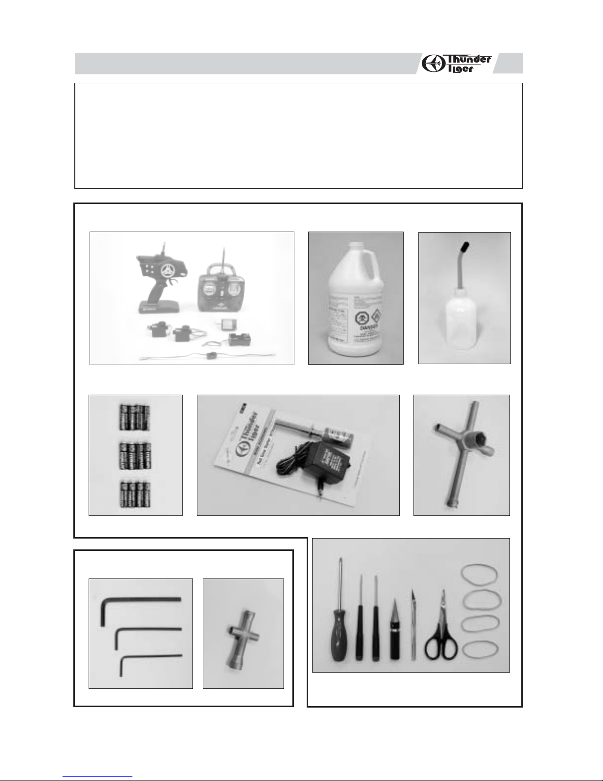
ITEMS REQUIRED FOR OPERATION
PURCHASED SEPARATELY
WITH ARTR MODELS
2-Channel, surface radio with 2 high torque servos
Alkaline Batteries
(12), AA-size
Glow Starter w/ Charger
TOOLS INCLUDED
Glow Fuel, Methanol
10% to 20% Nitro
5% to 18% Caster / Synthetic Oil
Fuel Bottle
5-Way Wrench
(300cc/600cc)
Hex Wrench Set 4-Way Wrench
Screw Drivers, Lexan Body Reamer, Hobby Knife,
Lexan Scissors, Rubber Bands.
1
Page 3
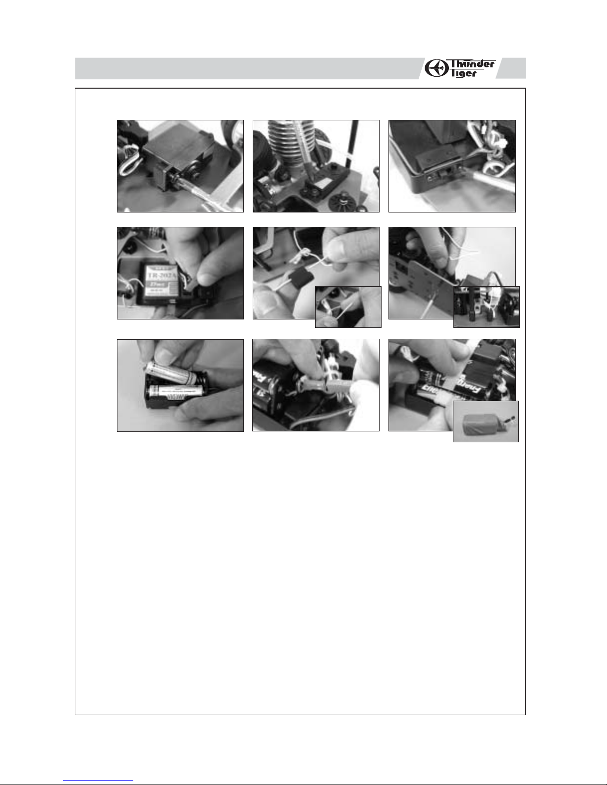
INSTALLING THE RADIO GEAR
skip if already assembled
1
a
b
ed
c
f
ihg
a.
b. Install the servos with tap screws. Notice the orientation of the steering and throttle servo output
shafts.
c. Install the receiver switch into the front of the battery mount with its original screws.
d. Properly plug the connectors/wires into the receiver: steering servo connector/wire into channel 1
slot, throttle servo connector/wire into channel 2 slot, and battery switch connector/wire into battery
slot.(Hint: Y ou can use small zip tie to arrange the rest of wires.)
e. Place the receiver antenna through the antenna mount and antenna tube as shown.
f. Press-fit the antenna tube into the mount, then secure the mount to the chassis using a 3x10 mm countersunk
screw.
g. Install 4 AA size alkaline batteries in receiver battery box.
h. Connect the receiver battery box wire/connector to the receiver switch wire/connector the receiver connector.
(Hint: Y ou can use small zip tie to arrange the rest of wires.)
i. Install the receiver and battery pack into the battery mount and use a large zip tie to secure. ( Note: It is strongly
suggested to cover receiver and battery pack with a balloon or plastic bag to protect against dirt and fuel )
2
Page 4
2
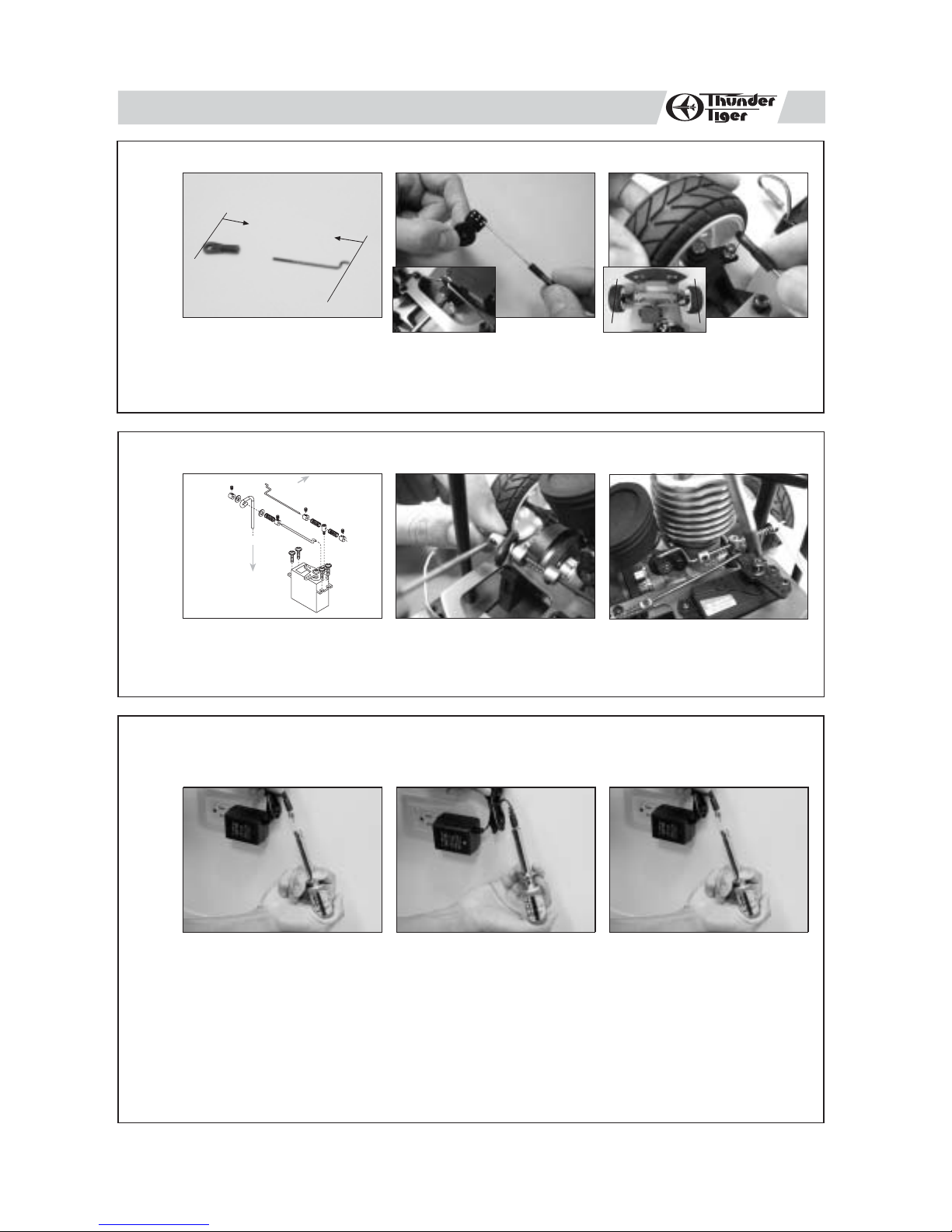
INSTALLING STEERING SERVO LINKAGE
a b
70 MM
AFTER INSTALLATION
a. Install the threaded of part of the linkage rod into the plastic tie-end. The linkage rod with tie-end should measure 70 mm when
finished.
b.
Install the steering linkage rod with tie-end onto steering servo horn
c.
Attach the tie-end onto the ball joint on the knuckle arms, making sure that the servo is centered and the axles have just a slight
amount of toe-in.
.
skip if already assembled
c
c
3
4
INSTALLING THROTTLE LINKAGE
To engine
carburetor
lever
To brake cam
a. Assemble the throttle and brake linkage as shown on the drawing.
b. Secure the brake linkage onto the brake lever with set screw.
c. Install the servo horn onto throttle servo output shaft.
skip if already assembled
cba
CHARGING THE GLOW PLUG IGNITER
Thunder Tiger Optional Part #2165, 1300MAH Glow Starter w/220V Charger.
Thunder Tiger Optional Part #2166, 1300MAH Glow Starter w/110V Charger.
a
b c
a. Plug the charger into an AC outlet, and then pull on the igniter lever to accept the charging adapter.
b. At this point, the small red LED indicator on the charger should light up indicating the charging sequence
is in progress.
c. When the charging complete, pull on the glow plug igniter lever to unplug the glow igniter.
Charge the new glow plug igniter for 16 to 24 hours on the first charge. For subsequent charges, charge
it about 12 hours before next use.
NOTE:
If the igniter gets warm or hot during the charge, unplug the igniter from charger immediately. A warm /
hot igniter means the igniter is overcharged. Overcharging can damage the internal battery in the igniter;
thus, shortening its life.
3
Page 5

PREPARING THE RADIO
5
6
a
a c
a. Check the frequency printed on the transmitter crystal.
b. Check the frequency printed on the receiver crystal, and make sure it matches with the transmitter
crystal. Make sure no one will operate on the same frequency when you are. When there is a radio
glitch, it will most likely be caused by improper crystal, damaged crystal, or people operating on the
same frequency.
c. Install the antenna into transmitter.
RADIO BATTERY INSTALLATION
b
c
abc
7
a. Install 8 AA-size alkaline batteries into transmitter.
b. Undo the large zip-tie, and remove the receiver battery box. Install 4 AA-size alkaline batteries into
receiver battery box.
c. Reinstall the battery box on the battery mount and tie with the receiver.
RADIO OPERATION
a
a.
When turning radio on, first turn on the transmitter.
b. Then, turn on the receiver. When turning off, first turn the receiver off, then the transmitter off.
c. To reverse the functions of servos, use the small, white servo reverse switches located on side of the
pistol transmitter (or the inset servo reverse switches located at the bottom of the stick transmitter). To
trim the servos on pistol transmitter, use the trim switches on side of the steering wheel (the ST. trims
steering, and the TH trims throttle/brake). On a stick transmitter, the trim levers are located accordingly
around the sticks.
For more details, please check the transmitter instruction manual.
b
c
4
Page 6

OPERATING RADIO STEERING FUNCTION
8
ab
a. Check the radio steering functions. With the radio transmitter and receiver on, turn the steering wheel/stick
to the left. The front tires/wheels should turn left accordingly. If not, flip the steering servo reverse
switch.
b. Return the steering wheel/stick to neutral. The front tires/wheels should point straight forward. If not,
use the steering trim lever to correct it.
c. Turn the steering wheel/stick to the right. The front tires/wheels should turn right accordingly.
c
9
OPERATING RADIO THROTTLE / BRAKE FUNCTION
a bc
a. Check the radio throttle/brake functions. With the radio transmitter and receiver on, pull the trigger/push
the stick forward. The carburetor should be fully opened and the brake disengaged. To reverse this
function, flip the throttle/brake servo reverse switch.
b. Return the trigger/stick to neutral. The carburetor should be closed to a point where the idle has
been set (see step for ADJUSTING THROTTLE/BRAKE LINKAGE), and the brake still disengaged. If
not, use the throttle/brake trim lever to correct it.
c. Push the trigger/pull the stick backward. The carburetor opening should still be the same at neutral,
throttle spring compressed slightly, and the brake engaged.
5
Page 7

ADJUSTING THROTTLE / BRAKE LINKAGE
10
a
a. To set the throttle/brake linkage, first the radio should be on and neutral; thus, the servo is at neutral
b. With the servo at neutral, turn and adjust the brake collar to a point where the brake lever almost
c. With the servo at neutral, loosen the throttle collars. Then, manually close the carburetor, and set
ADJUSTING CARBURETOR
b c
position.
engages the brake system, but not yet.
the collar (next to the spring) with the spring slightly compressed. Then, set the other collar next to
the linkage pivot.
11
a. To set the carburetor idle (small needle sticking out from the carburetor body), turn the screw as
b. To set the high speed needle (large needle sticking out from the carburetor body), turn the screw as
c. Remove the outer foam from filter and make it moist evenly with a few drops of fuel. If the vehicle
abc
pictured. Initial idle setting should leave 1mm carburetor gap. Clockwise turn will provide higher idle
(larger carburetor opening), and counterclockwise turn will provide lower idle (smaller carburetor
opening).
pictured. Initial high speed needle setting should be 2.5 turns (close the needle completely, then back
out 2.5 turns). Clockwise turn will provide leaner setting (lower fuel to air mixture), and counterclockwise
turn will provide richer setting (higher fuel to air mixture). Please refer to ENGINE BREAK-IN/SETTING
procedures to properly set the engine.
will be operated in an area with fine dust, use filter oil or caster oil instead of fuel. It is important that
the foam is only moist to trap dirt and allow air passage. With the foam too wet, limited air can pass
through; therefore, limiting engine performance. Finally, make sure the air cleaner boot is securely
fastened with a zip-tie.
6
Page 8

FUELLING
12
a
a. Remove the cap from fuel bottle nozzle.
b. Squeeze the fuel bottle, insert into fuel, and draw fuel into the fuel bottle. The fuel used should be
c. Fill car's fuel tank with glow fuel.
PREPARING THE ENGINE
13
b
methanol based model engine glow fuel (available at hobby shops) with 10% to 20% nitro content
and 5% to 18% caster/synthetic oil content for lubrication.
c
cba
d
a. To start an engine, first remove the glow plug.
b. Check the glow plug by plugging it into the glow plug igniter. The glow plug element should light up
brightly. If it lights up dimly, then the glow plug igniter is low (and it needs recharging). If it does not
light up or the plug element looks distorted, then the glow plug is bad (replace with new one). After
checking, reinstall the glow plug.
The glow plug used for this engine can be: Thunder Tiger 9281, McCoy #9 / #59,
Novarossi C4S / C5S / C6S,OS #8 / #A3 / #A5, and Picco P6S / P7S.
c. With the radio off, manually turn the servo to open the carburetor (open throttle).
d. Plug the tuned pipe exhaust tip.
e. Keeping the exhaust tip plugged, pull on the engine's starter . Keep doing it until fuel reaches engine's
carburetor, then pull it 3 more times to prime the engine.
f. Manually return the servo back to neutral.
e
7
f
Page 9

STARTING THE ENGINE
14
a b
a. Turn on the radio (transmitter first, then receiver).
b. Clip the glow plug igniter onto engine's glow plug.
c. Pull on the engine starter, release, repeat until the engine starts. Throttle maybe required to be opened momentarily, but
Remove the glow plug igniter from engine after engine has started and warmed up. If the engine stops right after the igniter is
removed, the carburetor setting is too rich. Please refer to engine setting section.
If engine starter becomes hard to pull, the engine maybe flooded. To unflood an engine, remove the glow plug from engine, flip
the car upside down, and pull on the starter to release excess fuel. Then, reinstall the glow plug and repeat the engine starting
procedure.
ENGINE BREAK-IN
For a new engine (break-in setting), the high speed needle needs to be set as rich as possible. Turn the high speed needle 1/4 turn
15
counterclockwise from initial setting (2.5 turns from fully closed). Repeat step 15b. Keep doing this until the engine stalls at full throttle,
then turn the high speed needle 1/4 turn clockwise. Run the car in an open parking lot with this rich engine setting for at least 5 tanks
of fuel to complete the break-in process. It is normal for a new engine to stall many times during this time due to the rich setting.
When it does, just restart the engine. After break-in, follow the ENGINE SETTING procedure to set the carburetor for normal operations.
ENGINE SETTING
Due to different fuel formula, operating elevation, humidity . . . etc., the engine may/may not operate properly at initial setting. Please
follow the following procedure to achieve proper carburetor setting. Do not perform this procedure until the engine has been properly
broken in.
a.Start the engine.
b.With a running engine, run the car back and foreth in a straight line (full throttle achieved furing each passage) in an open parking
lot. Repeat and note the sound of the exhaust. Do not hold the throttle open with car off the ground or the engine connecting rod
may break.
c.If the exhaust does not reach a high pitch note, turn the high speed needle (long needle, extending from carburetor body, pointing
up) 1/4 turn clockwise, and repeat step 15b.
d.Repeat step 15c until the engine reaches optimum setting (turning in the high speed needle will no longer have an effect at full
throttle and turning out the needle will cause the engine's full throttle rpm to drop a little). For normal operations, turn the high
speed needle 1/4 turn counterclockwise from the optimum setting.
e.To set the idle, turn the idle screw in (higher rpm) or out (lower rpm). Basically, the idle needs to be set at the lowest possible point
before the engine stalls.
f. To set the low speed needle (inside the throttle lever), the engine needs to be broken in and high speed needle needs to be set first.
g.Repeating step 15b every 10 seconds (1 second full throttle and 10 seconds idle). If the engine rpm at idle drops after a few seconds
and stalls, then turn in the low speed needle (clockwise) 1/4 turn. If the engine rpm stays the same or goes up at idle, then turn out
the low speed needle (counterclockwise) 1/4 turn.
h.Keep repeating step 15g until the engine rpm drops (goes to idle rpm, then drops a few more rpm after a few seconds) but does
not stall.
c
release throttle back to neutral immediately after the engine starts.
Thank you for purchasing a Thunder Tiger Product. Please read all instructions thoroughly before operation.
1. This product is not a toy. It is a high performance model product. It is important to familiarize yourself with the model, its manual, and its construction
before assembly or operation.
2. Do not operate model products in rain, on public roads, near crowds, near airport, or near areas with restricted radio operation.
3. Always keep fuel away from heat and open flame. Only operate in open, well-ventilated area. Store fuel in cool, dry area. Keep the fuel bottle
cap tightly closed. Clean up any leak or excess fuel before starting the engine.
4. This product, its parts, and its construction tools can be harmful to your health. Always exercise extreme caution when assembling and/or operating
this product. Do not touch any part of model which rotates.
5. Check your radio frequency with the proper operating frequency of the area or country. Always check to see if there are any modelers operating
on the same frequency as your are. Also, check your radio for proper operation before operating a mode.
6. Improper operations may cause personal and/or property damage. Thunder Tiger and its distributor have no control over damage resulting
from shipping, improper construction, or improper usage.
7. Thunder Tiger assumes and accepts no responsibility for personal and/or property damages resulting from the use of improper building materials,
equipment and operations. By the act of assembling or operating this product, the user accepts all resulting liability. If the buyer is not prepared
to accept this liability, then he/she should return this kit in new, unassembled, and unused condition to the place of purchase.
WARNING
8
Page 10

9437 PRO-12BXS Shown
28
19
10
7
15
13
16a
3
1
5
9222 CARBURETOR
C
17
27
11
12
8
4
16b
24
20
12
No. DESCRIPTION 9437 PRO-12BXS
25
17
22
1 PROP NUT AA0199B
23
26
32
21
17
33
3 DRIVE WASHER SET AA0245
4 CRANKSHAFT AA0244
5 CRANKCASE AN0195
6 BACKPLATE ******
13
7 CONNECTING ROD AN0433
8 WRIST PIN ASSEMBLY AN0188
10 CYLINDER & PISTON AN0547
11 CYLINDER HEAD AA1000
12 GASKET SET PN0009
13 CARB RETAINING BOLT PN0011
15 CARBURETOR ASSEMBLY 9222
16a BALL BEARING, FRONT AMV689Z
16b BALL BEARING, REAR AMV689
17 SCREW SET PN0012
19 AIR CLEANER SET 9262
20 ONE WAY CLUTCH SET AN0315
21 HANDLE SET PN0050
22 STARTING AXLE AA0313
23 STARTING SPRING AA0316
24 BACKPLATE AN0241
25 STARTING WHEEL WIRE AA0155
26 STARTING WHEEL AA0312
27 STARTING WHEEL COVER AN0314
F
H
J
28 STARTING SET PN0016
32 BACKPLATE & SCREW SET PN0017
33 STARTING WHEEL COVER SET PN0018
G
E
D
A
No. DESCRIPTION 9222
A CARBURETOR BODY W/ROTOR PN1123
B
B CARB. ROTOR ASSY PN1125
C NEEDLE VALVE ONLY PN1035
D SPRAY BAR ASSEMBLY PN1036
E NEEDLE VALVE ASSY. PN1037
F THROTTLE LEVER PN1038
I
G BOLT&FUEL INLET PN1039
H THROTTLE ROTOR SET PN1124
IO RING SET PN1041
J MIXTURE METERING SCREW SET PN1042
9
Page 11

For those who tired of their old lexan body,
we do have better choice!
All Touring car bodies are molded from crystal clear lexan and various
designs are available to meet your extreme demand. Thunder Tiger Corp.
guarantees that the items can fit all TS-N and UNO car series.
VOLVO S-40
PD0901 CLEAR BODY SET
PD1096 CLEAR BODY W/ DECAL
PD1097 PAINTED BODY SET
FORD FOCUS
PD1063 CLEAR BODY SET
PD1030 CLEAR BODY W/ DECAL
PD1065 PAINTED BODY SET
BENZ AMG C32
PD1394 CLEAR BODY SET
PD1395 CLEAR BODY W/ DECAL
PD1393 PAINTED BODY SET
MERCEDES BENZ
PD0903 CLEAR BODY SET
PD1098 CLEAR BODY W/ DECAL
PD1099 PAINTED BODY SET
DODGE STARTUS
PD1088 CLEAR BODY SET
PD1090 CLEAR BODY W/ DECAL
PD1091 PAINTED BODY SET
BMW M3 GT
PD1400 CLEAR BODY SET
PD1401 CLEAR BODY W/ DECAL
PD1399 PAINTED BODY SET
ALFA ROMEO
PD0905 CLEAR BODY SET
PD1100 CLEAR BODY W/ DECAL
PD1101 PAINTED BODY SET
PEUGEOT 206
PD1069 CLEAR BODY SET
PD1029 CLEAR BODY W/ DECAL
PD1071 PAINTED BODY SET
DODGE VIPER GTS-R
PD1403 CLEAR BODY SET
PD1404 CLEAR BODY W/ DECAL
PD1402 PAINTED BODY SET
SUBARU IMPREZA WRC
PD1406 CLEAR BODY SET
PD1407 CLEAR BODY W/ DECAL
PD1405 PAINTED BODY SET
OPEL ASTRA V8
PD1412 CLEAR BODY SET
PD1413 CLEAR BODY W/ DECAL
PD1411 PAINTED BODY SET
Page 12

UNO 1/10 2WD On-Road Nitro Racer
Thunder Tiger's new on-road nitro racer brings the feel
and excitement of nitro racing to parking lot racers
everywhere! Not only will this be the economical nitro
combo, it will also be the most convenient. With 100%
assembly, this new racer is ready to hit the asphalt when
it comes out of the box.
A durable pan-style chassis features independent front
A-arm suspension and rear T-plate with mono shock for
sure, precise handling. A straight axle rear end provides
instant power transfer to the pavement, and the
breaking system. supplies sure stopping power.
The included TT PRO-12BXS engine features a recoil
starting system for fast, easy starts, and the 75cc fuel
tank provides long run times between pit stops.
For details, it adds a reinforced rear shaft mount &
hub to enhance durability and rigidity of shaft. A muffler
protection wire assures the UNIQUE muffler keeping
away from unexpected damage.
PRO-12BXS
BMW M3 GT
SUBURU IMPREZA WRC 02'
2-channel Radio
THUNDER TIGER CORPORATION
DODGE VIPER GTS-R
www.thundertiger.com.tw
 Loading...