

1
Thunder Tiger G202-140 ARF Airplane (TTR4550)
Distributed in North America by Ace Hobby Distributors,Inc.• 116 W 19th ST,Higginsville, MO 64037
Phone:660-584-7121 • www.acehobby.com • email:service@acehobby.com
Assembly Manual
Wing Span: 70"
Wing Area: 1022 in2
Length: 70"
Weight: 10-10.5 lbs
Engine: 1.08-1.6 2 Cycle
1.2-1.8 4 Cycle
Radio: 7 Channel w/6 Servos
Specifications:
Warranty
This kit is guaranteed to be free from defects in material and workmanship at the date of purchase.
It does not cover any damage caused by use or modification. The warranty does not extend beyond the
product itself and is limited only to the original cost of the kit. By the act of building this user-assembled
kit,the user accepts all resulting lliability for damage caused by the final product. If the buyer is not
prepared to accept this liability,it can be returned new and unused to the place of purchase for a refund.
JE6328
Notice: Adult Supervision Required
This is not a toy. Assembly and f lying of this product requires adult supervision.
Read through this book completely and become familiar with the assembly and f light of this airplane.
Inspect all parts for completeness and damage. If you encounter any problems,call 660-584-6724 for help.

2
INTRODUCTION
PRE-ASSEMBLY NOTES
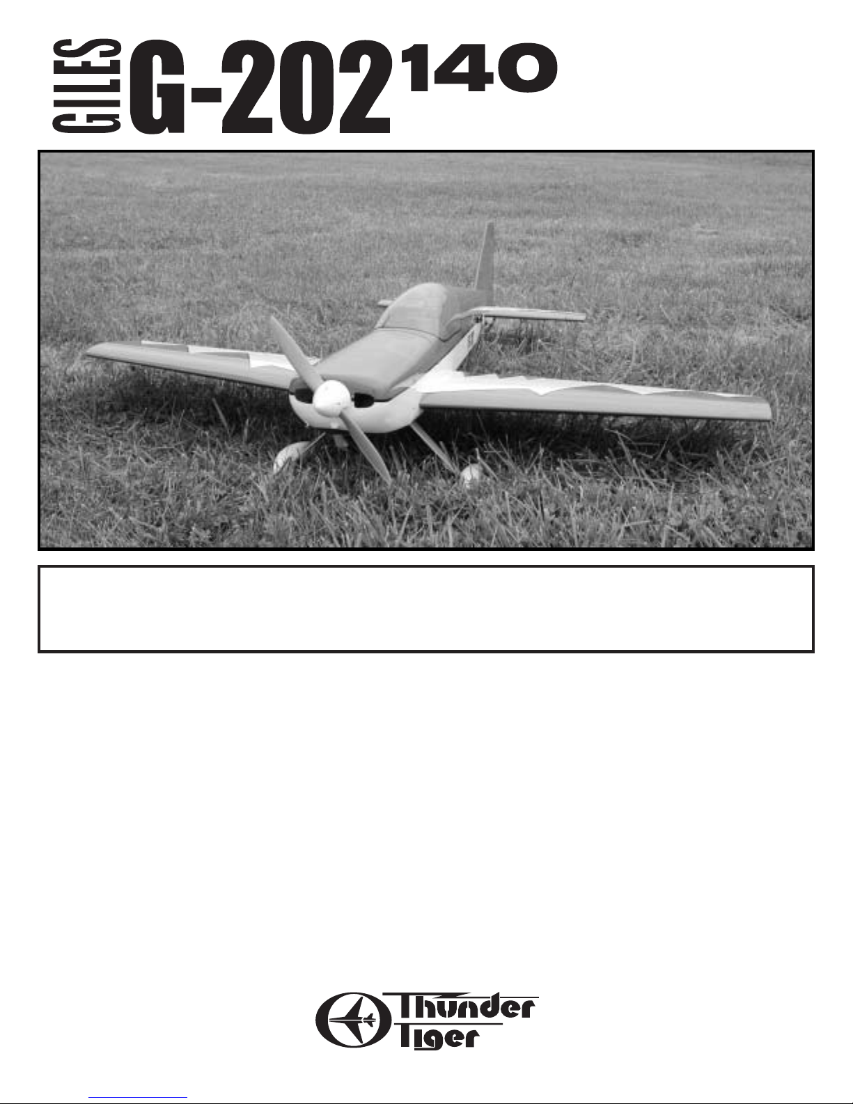
Congratulations on the purchase of one of our finest ARFs to date. This scale replica of the famous Giles
G-202 is as faithful in its appearance as it is in its flight characteristics. Beautifully reproduced using balsa and
ply construction. Covered in durable and easily repairable UltraCote®,this plane is highly visible in the air
and strikingly recognizable on the ground.
Before beginning the assembly r ead the instructions thoroughl y to give an understanding of the sequence
of steps and a general awareness of the recommended assembly procedures.
By following these instructions carefully and ref erring to the corresponding pictures,the assembly of your
model will be both enjoyable and rewarding. The result will be a well built,easy to assemble ARF model,
which you will be proud to display.
This G202-140 is designed for intermediate to advanced pilots, and this manual assumes a basic knowledge of R/C model construction.
Before you begin,check the entire contents of your kit against the parts list and photos to make sure that
no parts are missing or damaged. This will also help you to become familiar with each component of your
plane. If you find that any of the parts are either missing or damaged,please contact Ace Hobby Distributors,
Inc.,Customer Ser vice (660-584-6704) immediately for replacements.
Please read the entire manual before beginning construction.
Neither your dealer nor Ace Hobby Distributors, Inc., can accept kits for return if construction has
begun.
Trial fit each part before gluing it in place. Make sure you are using the correct part and that it fits well
before assembling. No amount of glue can make up for a poor- fitting part.
Introduction . . . . . . . . . . . . . . . . . . . . . . . . . .2
Items Needed Check List . . . . . . . . . . . . . . .3
Parts Sketches . . . . . . . . . . . . . . . . . . . . . . .4-5
Wing Assembly . . . . . . . . . . . . . . . . . . . . . .6-9
Stabilizer Assembly . . . . . . . . . . . . . . . . . .9-11
Elevator Servos . . . . . . . . . . . . . . . . . . . .11-13
Tailwheel . . . . . . . . . . . . . . . . . . . . . . . . . . .13
Landing Gear . . . . . . . . . . . . . . . . . . . . . .13-14
Engine . . . . . . . . . . . . . . . . . . . . . . . . . . . 14-15
Fuel Tank . . . . . . . . . . . . . . . . . . . . . . . . .15-16
Cowl . . . . . . . . . . . . . . . . . . . . . . . . . . . . 16-17
Switch & Receiver . . . . . . . . . . . . . . . . . . . .17
Wing Attachment . . . . . . . . . . . . . . . . . . . . .17
Pilot . . . . . . . . . . . . . . . . . . . . . . . . . . . . . . .17
Canopy . . . . . . . . . . . . . . . . . . . . . . . . . . . .18
Prop & Spinner . . . . . . . . . . . . . . . . . . . . . . . .18
Control Throws . . . . . . . . . . . . . . . . . . . . . . . .18
CG,Flight Tips . . . . . . . . . . . . . . . . . . . . . . . . .19
TABLE OF CONTENTS
3
RECOMMENDED TOOLS & MATERIALS
Adhesives:
Instant setting cyanoacrylate adhesive (thin CA)
Slower setting cyanoacrylate adhesive (medium CA)
5 Minute Epoxy (fast)
20-30 Minute Epoxy (slow)
R/C 560 Canopy Glue
Zap-A-Dap-A-Goo II™
Tools:
Model knife,T-Pins,1/2”vinyl tape
Small screwdrivers,medium screwdrivers
Lexan Scissors
Steel straight edge
Long nose pliers and diagonal cutting pliers
Drill and drill bits
Dubro 8-32 tap
Sanding block
Fine felt tip pen and soft lead pencil
Straight building board
R/C System:
Seven channel radio with one standard servo and
five dual BB high torque servos
Four 12" aileron extensions
One servo reverser Y-harness
Engine:
2 cycle: 1.08-1.60
4 cycle: 1.20-1.80
Propeller (appropriate for engine type and
preferred performance)
Radio - A 7-channel radio with 5 high performance servos
and 1 standard servo is required.
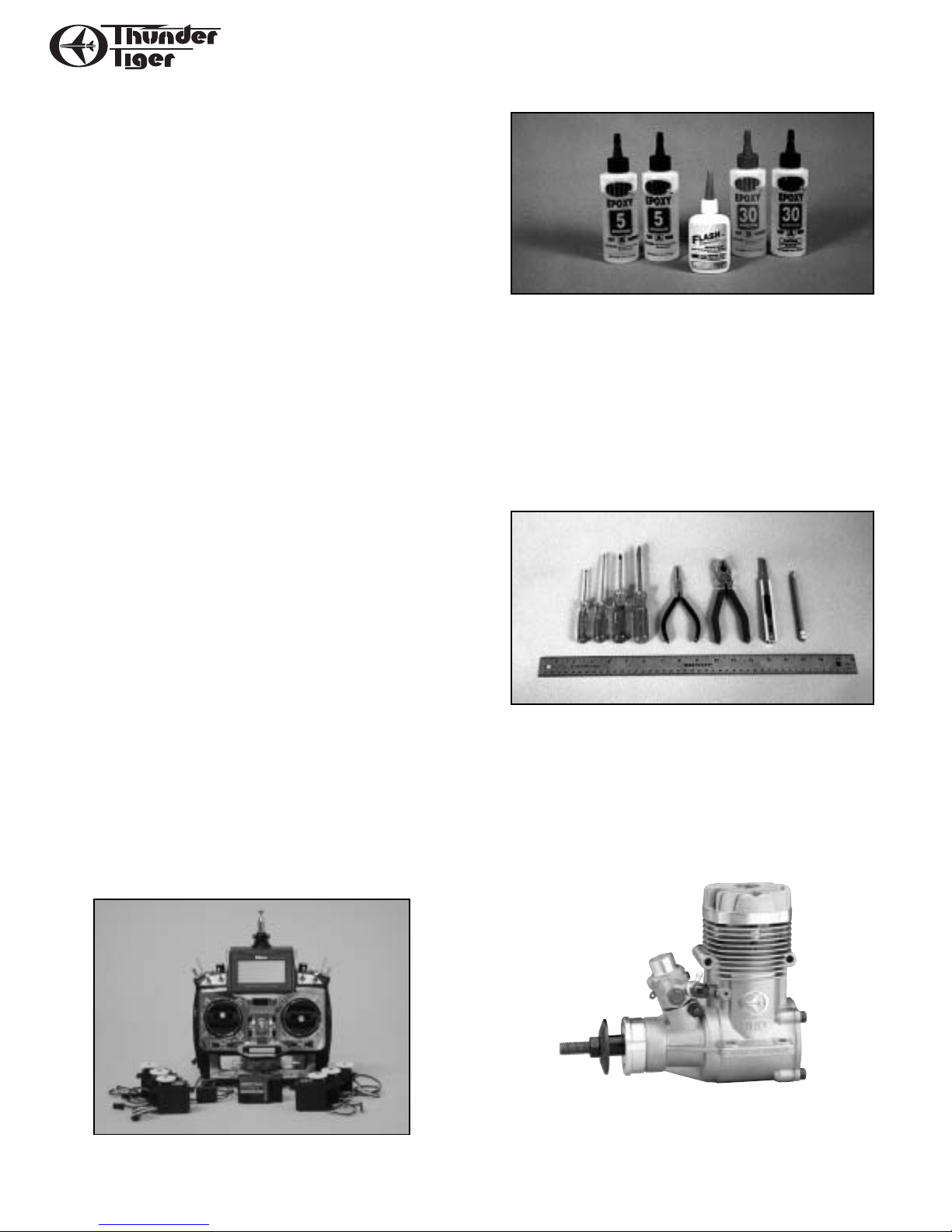
Adhesives - You will need two types of adhesives
for the G202-140 - Epoxy and Instant (cyanoacrylate) adhesives. We recommend that you purchase
both 5-minute and 30-minute epoxy to cut down on
assembly time, but you can get by with only 30minute epoxy if time is not important. You will also
need a small bottle of both “Thick” and “Thin”
instant CA adhesive.
Tools - Model assembly can be much easier if the
proper tools are used. Therefore, we have included
in our checklist to the left, a complete listing of all
the tools we used to assemble our prototype models. As you will notice, many household tools can be
utilized during construction.
Engine - The Thunder Tiger PRO-120 is the ideal
engine for this airplane.This quiet-running engine is
easy to start, requires no special break-in periods,is
very easy to maintain and will last for years.
4
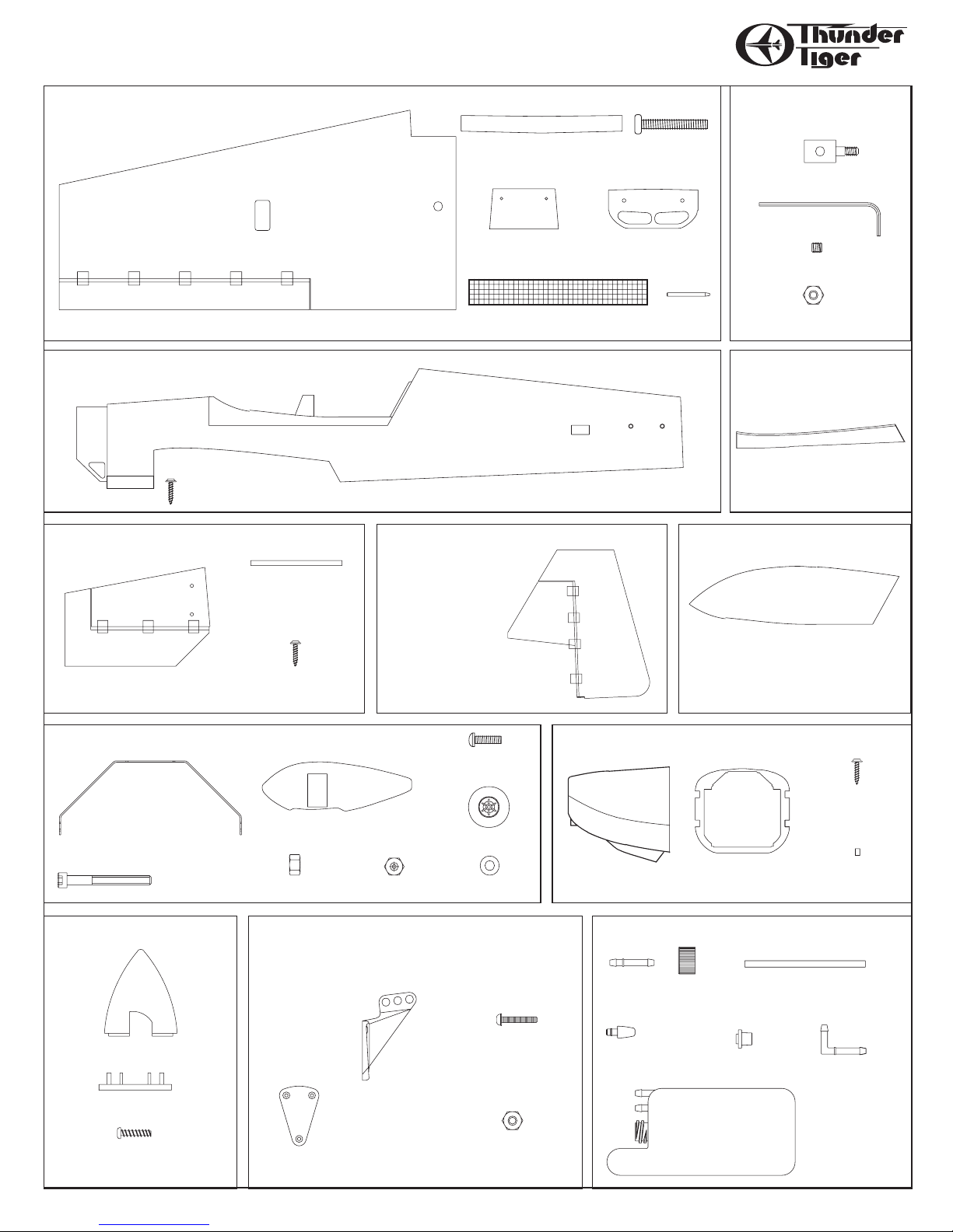
PARTS DRAWINGS
Main Landing Gear(1)
Wheel Pant(L/1, R/1)
AS6149 Main Landing Gear
4mm Nut(4) 4mm Locknut(2)
Wing Bolt Plate(1)
AS6146 Main Wing Set
Wing Joiner(4)
4mm Washer(2)
Main Wing( L/1 R/1)
Belly Front Former(1)
Fiber Cloth(1)
Dowel(2)
Wing Bolt(2)
AS6145 Fuselage
Fuselage(1)
2.3mm x 12mm Wood Screw(4)
AS6147 Horizontal Tail
stab./Elevator( L/1,R/1)
Carbon Tube(2)
2.3mm x 12mm
Wood Screw(4)
AS6148 Vertical Tail
Vertical Fin/Rudder(1)
Wheel(2)
4mm x 40mm
Socket Screw(2)
4mm x 16mm
Machine Screw(3)
AS6151 FRP Belly Pan
FRP Belly Pan(1)
PE0009 Hardware Set
(Sold in Pair)
2mm Hex Nut(1)
3mm x 3mm Set Screw(1)
Pushrod Connector(1)
Allen Wrench(1)
Canopy (1)
AS6152 Canopy
FRP Cowl(1)
AS6150 FRP Cowl
Mounting Ring(1)
2.3 x 12mm
Wood Screw(4)
Mounting Block(4)
Back Plate(1)
3mm x 12mm
Self-Tapping Screw(4)
No.3278W Spinner
720 c.c. Tank(1)
Fuel Stopper(1)
Cap(1)
90-degree Nipple(1)
Silicone Tube(1)
Nipple(1)
No.3272 Fuel Tank Set
Clunk (1)
No.3013 Swivel Ball Link Control Horn Set
(Sold in Pair)
2mm Hex Nut(15)
Back Plate(4)
2mm x 22mm
Screw(15)
Spinner(1)
Control Horn(6)
5
PARTS DRAWINGS
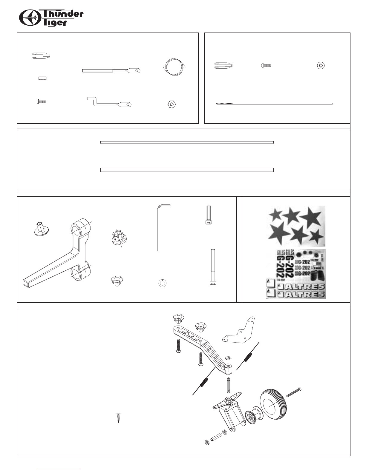
No.3014 Pull-Pull System
Clevis(2)
Threaded End(2)
2mm x 8mm
Screw(2)
Bass Tube(8)
2mm Hex Nut(2)
Z-Bend End(2)
Cable(1)
No.3015 Scale Tail Gear
Blind Nut(2, Installed in the Fuse.)
Tail Gear(1)
4mm x 20mm Sink Head Screw
Spring (2)
Control Horn(1)
E Clip(1)
Steering Shaft(1)
Steering Fork(1)
2.6mm x 26mm
Sink Head Screw(1)
Tire(1)
Tail Wheel(1)
Plastic Washer(2)
Wheel Spacer(1)
2.3mm x 12mm
Wood Screw(2)
No.3012 Anti Vibration Engine Mount
Mounting Beam(2)
TWasher(8)
Rubber(8)
Blind Nut(4)
5mmx40
Socket Screw(4)
Hex Wrench(1)
Spring Washer(4)
Eng Mounting Screw
6/32 x 20mm(4)
4mm x 20mm(4)
AS6154 Decal
AS6153 Piano Wire
Piano Wire(1)
No.3016 2.3mm Pushrod Set(Sold in Pair)
Dia 2.3mm(0.09") Pushrod (4)
Wire Guide(1)
2mm Hex Nut(4)
Clevis(4)
2mm x 8mm
Screw(4)
6
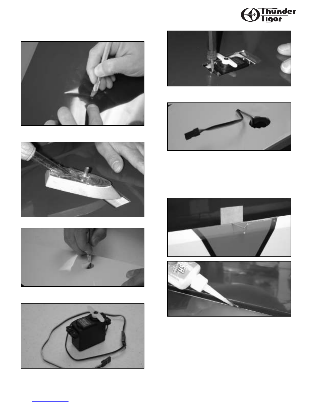
WING ASSEMBLY
I. Mount Ser vos
❐ With the wing panel upside down,locate the servo well and cut an
X from corner to corner using an Xacto knife.
❐ Use a sealing iron to tack down the covering inside the servo well.
❐ With the wing rightside up, locate the servo wire exit hole and
remove covering.
❐ Attach the 12" aileron extension lead to the servo.
❐ Install the servo in the wing. Use a servo arm instead of the
standard wheel.
❐ Use a piece of clear tape to temporarily hold the servo pigtail to the
wing to prevent it from slipping back into the wing while you are
working.
II. Install Ailerons
❐ Remove the aileron and insert T-pins into the centers of the hinges.
Install aileron onto the wing,remove T-pins,and apply thin CA to the
hinges (both sides).
 Loading...