

Page 1
1
Sparky ARF Airplane (TTR4307)
Distributed in North America by Ace Hobby Distributors,Inc.• 116 W 19th ST,Higginsville,MO 64037
Phone:660-584-7121 • www.acehobby.com • E-mail:service@acehobby.com
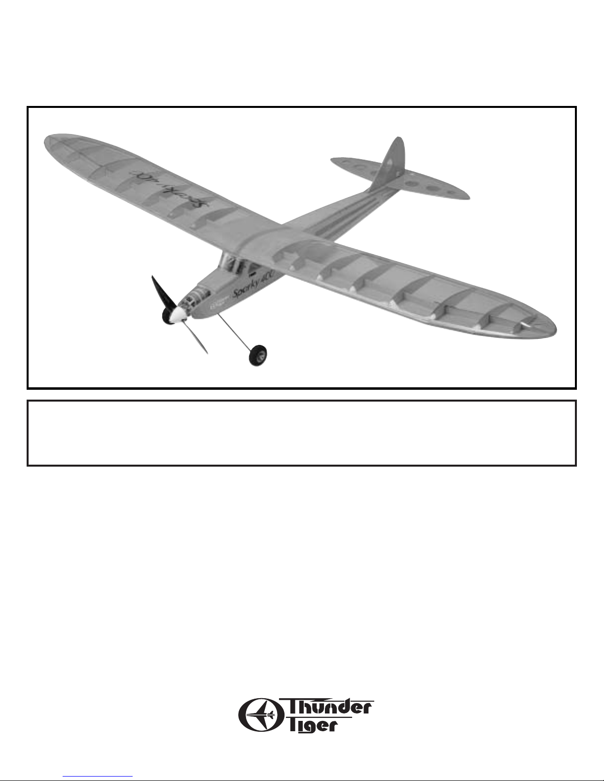
Sparky ARF
Assembly Manual
Wing Span: 57”(1450mm)
Wing Area: 360sq.in.(23.2dm2)
Length: 34”(865mm)
Weight: 1.6 lbs.(700-750g)
Motor: 400 Motor req’d
Radio: 2~3 channel
Specifications:
Warranty
This kit is guaranteed to be free from defects in material and workmanship at the date of purchase.
It does not cover any damage caused by use or modification. The warranty does not extend beyond the product itself and is limited only to the original cost of the kit. By the act of building this user-assembled kit,the
user accepts all resulting liability for damage caused by the final product. If the buyer is not
prepared to accept this liability,it can be returned new and unused to the place of purchase for a refund.
JE6454
Notice: Adult Supervision Required
This is not a toy. Assembly and flying of this product requires adult supervision.
Read through this book completely and become familiar with the assembly and f light of this airplane.
Inspect all parts for completeness and damage. If you encounter any problems,call 660-584-6724 for help.
Page 2
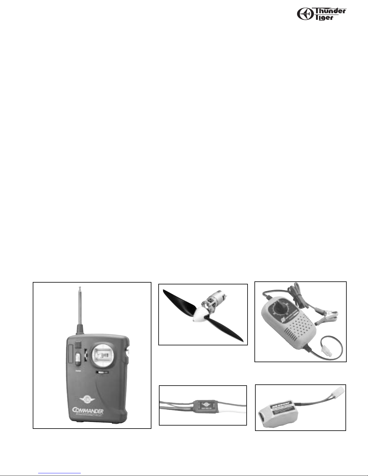
ITEM NEEDED FOR COMPLETION
Motor - Thunder Tiger Electric
Power System includes 400 motor,
1:2 gear reduction set,9 x 6 propeller and spinner.
2
INTRODUCTION
The Sparky is reminiscent of a time when things were more relaxed and life happened at slower pace;
everything was simpler...easier.
Now you can enjoy this "old-timer" feeling with these Almost-Ready-To-Fly planes. A large wing span,high
aspect ratio eliptical wing provides ultra-stable and slow flight, perfect for the beginner or an experienced
pilot looking for relaxation.
Pre-Assembly Notes
Before beginning the assembly r ead the instructions thoroughl y to give an understanding of the sequence
of steps and a general awareness of the recommended assembly procedures.
By following these instructions carefully and ref erring to the corresponding pictures,the assembly of your
model will be both enjoyable and rewarding. The result will be a well built, easy to assemble ARF model,
which you will be proud to display and also provide you considerable enjoyment.
If you are not an experienced R/C pilot,plan to have a fully competent pilot c hec k y our completed model
and help you with your first flights. Even though we have tried to provide you with a very thorough instruction manual, R/C models are rather complicated and an experienced modeler can quickly check over your
model to help make sure your first flights are successful.
Before you begin,check the entire contents of your kit against the parts list and photos at back cover to
make sure that no parts are missing or damaged. This will also help you to become familiar with each component of your plane. If you find that any of the parts are either missing or damaged, please contact Ace
Hobby Distributors,Inc.,Customer Service (660-584-6704) immediately for replacements.
Trial fit each part before gluing it in place. Make sure you are using the correct part and that it fits well
before assembling. No amount of glue can make up for a poor-fitting part.
Charger - Ace R/C 8.4V 60 min.
DC Quick Charger
8.4V Battery Pack - AcePower
8.4V 900mAh NiMH battery Pack
Radio - A 3-channel radio with three standard
or mini servos is required. The Ace R/C
Commander is ideal.
ESC - Ace R/C Electric Speed
Control Unit ESC-30
N0.8301
AS6162
8012AC
2604AC
2919AC
Page 3
3
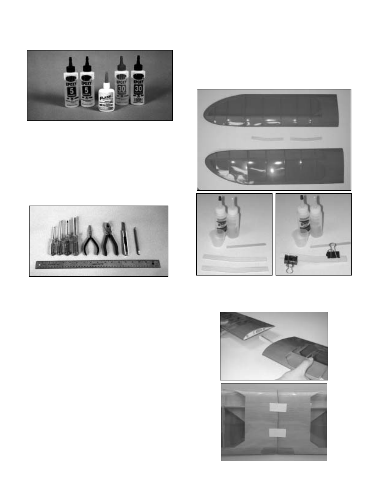
WING ASSEMBLYTOOLS & MATERIALS
Adhesives -You will need two types of adhesives for the
Sparky - Epoxy and Instant (cyanoacrylate) adhesives. We
recommend that you purchase both 10-minute and
30-minute epoxy to cut down on assembly time,but you
can get by with only 30-minute epoxy if time is not
important. You will also need a small bottle of both
“Thick”and “Thin”instant adhesive.
Tools - Model assembly can be much easier if the proper tools are used. As you will notice, many household
tools can be utilized during construction. Besides above
tools, some other tools or materials like T-Pins, Scissors,
Drill and Drill Bits, Fine Felt Tip Pen, Rubbing Alcohol,
Masking Tape will be used when assembling.
I. Wing Assembly
A. Locate both wing halves and the two dihedral braces.Mix a small
amount of 5-minute epoxy and glue both dihedral braces together.
With the two dihedral braces together trial fit the braces in each wing
half.With dihedral brace in one wing panel,trial fit it to the other wing
panel,assuring no gaps from leading edge to trailing edge.
B. Mix up a small amount of 30 minute epoxy and apply to both
sides of both inner ribs and dihedral brace slot.Insert brace into one
wing panel before putting wing panels together. After wings are
together,wipe off excess epoxy,tape and set aside to cure.After epoxy
is cured,glue the wing protector at the joint of the trailing edge.
Page 4
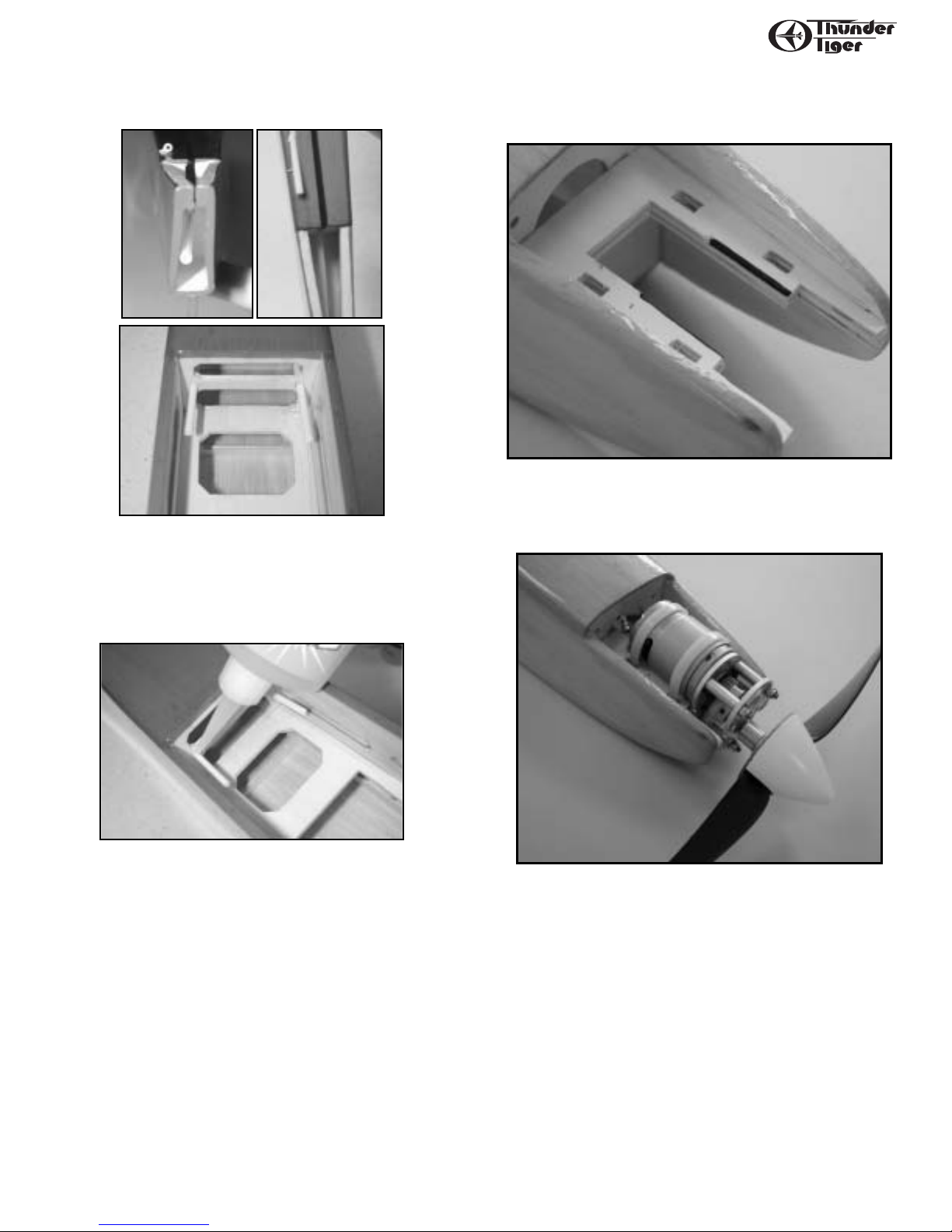
hold pushrod tubes in place.
III. Motor Installation
A. File the motor mount at the beam as shown for better fitness.
4
FUSELAGE
II. Pushrod Housing Installation
A. Carefully install rudder and elevator pushrod tubes;insert the elevator pushrod tube through the hole in the rear former through the
fuselage and out the pre-drilled hole in the right of the rear cabin former.
B. With a hobby knife,remove covering from existing slot in top rear
of fuselage and insert rudder pushrod tube through fuselage and out
pre-drilled hole in left rear cabin former. Use just a dab of CA glue to
R
L
Page 5

5
STABILIZER
B. Secure the motor tightly with enclosed Zip-Tie.
IV. Wing Hold Down Dowel Installation
A. Cut away the covering film from the predrilled holes in the fuselage with a hobby knife.
B. Install dowels and place a drop of medium CA to hold dowels in
place.
V. Stab and Rudder Installation
A. Center the main wing on the fuselage and attach using the rubber
bands provided.
B. Determine the top and bottom of the stab like this: the sealed
edge of the elevator should be on top,and the beveled edge be on the
bottom.
C. Place the stab on the tail of the plane and measure from points
shown above. This will square the stab in the saddle. Pin the stab in
Page 6

6
STABILIZER
place with T-pins,and mark the bottom of the stab.
D. Remove the stab and place top-down on a flat surface so you can
see the markings you just made. With a small steel rule,place it on the
inside of the lines about 1/16". Using an Xacto knife,cut to remove the
covering from the stab.BE CAREFUL NOT TO CUT TOO DEEP AS YOU
MAY WEAKEN THE STABILIZER. TRY TO CUT ONLY THE COVERING.
E. Use a hobby knife to remove the covering film from the fin slit in
the tail of the plane.
F. Trial fit stab and fin to fuselage before gluing. Mix a small amount
of 15 minute epoxy and glue the stabilizer into place,rechecking your
alignment marks by remeasuring as shown in previous step to insure
proper alignment of stab and wing.
G Insert the fin into the slot in the tail and mark the fin as shown.
Remove the fin and use a hobby knife and straightedge to remove the
covering film from the bottom of the fin.AGAIN,BE CAREFUL NOT TO
CUT TOO DEEP AS YOU MAY WEAKEN THE STABILIZER. TRY T O CUT
ONLY THE COVERING.
H. Apply some thick CA to the bottom rear of the fin and insert it
into the slit. Use a 90 degree triangle to square up the fin with the stabilizer. Next wick some thin CA in the joint where the fin meets the
slit.
I. Mount the rear control horns;place the control horn on the bottom center of the elevator in line with the pushrod tube. Mark the
Page 7

7
LANDING GEAR
holes for the control horn using a felt marker.
J. Attaching the control horn using two 2mm screws and backing
plate.It might be wisely to connect the pushrod at the z bent end and
insert the pushrod to the tube before installing the control horn.
Attach the rudder control horn in the same manner.
Note: The longer pushrod is for elevator, the short one is for rudder.
VI. Landing Gear Installation
A. Landing gear is assembled with 4 wheel collars,2 bushing,and 2
wheels. Install one wheel collar on to the landing gear,then slide the
brass bushing on,slide the wheel over the bushing, and finally install
the second wheel collar. Repeat process for other wheel.
B. Using a hobby knife remove the covering over the landing gear
slot. Push the landing gear down into the slot. Apply a few of drops
of medium CA into the slot and slide the former into place. WARNING:
WHEN YOU INSERT THE FORMER,IT WILL SQUIRT EXCESS CA OUT
THE HOLES NEAR THE LANDING GEAR,SO BE CAREFUL!!
VII. Servo, Radio,Battery,& Switch Installation
A. Using a hobby knife remove the cov ering film from the s witch cut
out on the left side of the fuselage.
B. Glue the two plywood pieces as the servo tray if you use the mini
servo. You might place your mini servo as a guide then glue the ply-
Page 8

8
RADIO
wood in place.
C. Secure the mini servo in place as shown.Install the EZ connector
on the servo horn.Insert the pushrod first then place the hor n on the
servo. Make sure the servos are in neutral position then screw the
horn.
D. Install the receiver,ESC,battery back as shown.Please refer to the
manufacturer's instruction manual for correct connection.Poke a hole
in the bottom of the cabin and run the antenna out and down the bottom of the fuselage and attach to the tail using whatever method you
prefer.
E. Install the ESC switch
VIII. Balancing
E. Balance the plane. With the wing on the airplane, use your two
index fingers to suspend the model in the air. Locate your fingers 1
1/4”back from the leading edge of the wing,about 4”out from the fuselage. At this point,a right angle is formed where the leading edge and
the center balsa sheeting ends. You can feel this point with your finger
tips.
The plane should hang level or slightly nose down at this point. If
the tail drops,you need to redistribute or even add weight to the nose
until the plane balances.
IX. Control Throws
Make sure that all control surfaces move in the proper direction.
Set the control surface throws as indicated for the initial flights.
These may be altered later for personal preference.
3/4”
neutral
3/4”
1/2”
neutral
1/2”
Rudder
Elevator
Page 9

9
RADIO/PREFLIGHT
X. Pre-Flight
❐ Prior to the first flight ensure that all batteries are properly
charged,that controls all move in the proper direction,and that a
thorough range check is made with and without the motor running.
❐ Rubber band the wing on using six rubber bands to secure the
wing. Use one on both the right and left side,then crisscross two
more from the right front to the left rear and crisscross the final
two from the left front to the right rear.
❐ Choose a calm day for your first flights. Also,choose an open field
with no obstacles or people.
❐ Make sure there are no other pilots operating on on the same
channel (frequency) as you are. If you turn your radio on while
he is flying, you will cause him to crash.
❐ Check you radio for good range (50 ft. with the antenna
collapsed) and proper operation.
❐ MAKE SURE NO ONE IS OPERATING ON YOUR FREQUENCY
(Channel number). Any flying field has rules to govern frequency
usage. Make sure you abide by them.
❐ Refer to your radio instruction manual for the proper ground
range you can e xpect from y our system. Perform this range check
each flying session.
❐ Check the motor,gear & propeller to make sure that everything
are secured.
❐ The rotating propeller is very dangerous, always switch on the
THE DIRECTION OF MOVEMENT (RUDDERAND ELEVATOR)
NEUTRAL RIGHTTURN LEFTTURN
Check the position of rudder and
elevator (if these are in neutral).
Set the trim in neutral position.
Move the stick to the right. Move the stick to the left.
Set the sticks in neutral position
Move the stick up. Move the stick down.
UPDOWN RIGHTAND UP
Move the stick down and right.
Page 10

10
GENERAL FLYING
transmitter first and make sure the throttle control stick or slide
throttle( ACE T3S) is at idle position.
XII. Flying
You should have a flight instructor teach you how to fly the
Sparky. Like a real airplane,you must have an understanding of how to
fly the model before launch, or you will probably not be successful.
Check at your hobby shop or call the AMA (800-435-9262) or surf its
website at www.modelaircraft.org for flying clubs in your area.
Take-off
A proper hand-launch of the airplane is necessary for flight. It
must be launched into the wind with a firm toss. The airplane must be
tossed level or even pointed a little down. It should never be thrown
upward,or it will stall and crash.
Flight
Steer very gently right and left to keep the wings level. Let the airplane climb out gradually and gently until it reaches a comfortable
cruise altitude at full flight speed. Always keep the airplane upwind of
yourself and within a reasonable distance so you can see what it is
doing. Remember,when the plane is coming toward you,when you
move the stick to the right, the aiplane will go to the left from your
point of view. This is the hardest thing to learn. Initially,you can keep
your body pointed in the same direction as the airplane and look over
your shoulder
Usually,only small stick movements are required.Try to keep your
flying smooth. You can turn the plane by bumping small amounts of
rudder and then return to neutral. Use the elevator to keep the airplane at the desired altitude. After a while,coordinate your turns with
the elevator;i.e., bank the plane with a little bit of r udder,then feed in
some up elevator to maintain the turn at the same altitude. If the plane
tends to turn one way or the other use the trim lever on the control
stick to neutralize the flight. Same thing applies if the place wants to
climb or dive.
Landing
Set up your landing approach. Always try to land INTO THE
WIND. Keep your turns gradual and only use elevator to maintain a
gradual glide. Since the motor is off,you can no longer climb and the
plane slows down. If you feed in too much up elevator,the plane will
stall and may crash.
Just before touchdown,“f lare” the plane by adding up elevator.
The plane should slow down even more and come in for a g entle landing. Don’t add too much elevator,too soon!
Walk over to the plane and turn of f the switch on the plane,then
the transmitter switch. Check over the plane to make sure nothing
loosened up or broke.
In Case of Trouble
If the radio is erratic (glitches), check that the transmitter and
receiver antennas are extended to their full length. Make sure the
transmitter batteries are fresh. Make sure no one else is operating on
your channel (frequency) in the immediate vicinity.
If the plane does not fly properly,make sure you are being gentle
with the control inputs. Make sure the plane is balanced properly.
If your trouble persists,call 660-584-6724 for technical help.
Conclusion
To defeat the laws of gravity and take to the wing is both
challenging and thrilling. We hope you enjoy your entry into the
fascinating world of R/C flight and make it your hobby for a lifetime.
Please let Ace R/C and Thunder Tiger be your chosen brand,no matter
what direction you progress.
XIII. Post-Flight
Turn off all switches and if you are done for the day,clean-up your
plane with some spray cleaner (such as 409) and paper towels. While
you are cleaning the plane up,inspect it for damage...check the prop
for dings or chips. Spray some WD40 on and in the gear section and
motor shaft for better lubrication.
XIV. Safety Precautions
1. Take great attention to the motor and propeller as they might be
deadly weapon when rotating.
2. Always switch on the Transmitter first and make sure the throttle
at the “Down”position then switch on the ESC switch.
3. Always stay behind the propeller when the motor is running.
Only switch on the motor when you are ready for launching.
Under no circumstances should you allow your face or body
near the plane on rotation of the propeller when motor is run-
ning.
4. Do not allow loose clothing or other loose objects close to the
prop.
5. To stop a motor,switch off the power or move the throttle stick
down.
6. Move the throttle stick (slide throttle) down to switch off the
power immediately in case of any CRASH,HEAVY LANDING and
NOSE DOWN or any situation that prop could not rotate freely as
it might damage the ESC and motor.
XV. Repair
In the event of a minor mishap, the Sparky usually can be
repaired. Begin by completely cleaning the area being repaired with
alcohol to remove any oil residue.
* Balsa components can be glued back together with CA glue.
* If you need to repair around the firewall/motor mount area, use
epoxy.
* Locate the covering film and heat iron for patching at your local
hobby shop if necessary.
Page 11

11
FLYING
Wind Direction
Example of a turn using
only rudder
Example of a turn using
rudder then elevator
Launch
Landing
Launch firmly into wind straight and level.
Do not throw upwards or the plane will
stall and crash!
Correct
Straight
level with ground
and
Incorrect
Wind
Wind Direction
3 ft.
Page 12

PARTS DRAWINGS
AS6159 Wing Set
AS6023 Control Horn Set
PE0009 Hardware Set
AS6160 Pushrod Set
AS6164 Decal
IMPORTANT
Please check the contents of your kit box with these part sketches before beginning
construction. This will not only familiarize you with the parts and their names, but it
will also give you a head start in the unlikely event that you are missing a part.
Parts are not necessarily drawn actual size
AS6166 Vertical T ail
AS6158 Fuselage
AS6142 Landing Gear Set
AS6165 Horizontal Tail
Fuselage(1)
Wheel (2)
Z Bent Pushrod (2)
2mm HEX Nut (2)
Control Horn Back Plate(2)
Plastic Guide Tube (2)
Main Landing Gear (1)
3mmx5mm Screw (2)
Collar (2)
2mmx8mm Screw (4)
Pushrod Connector (2)
Allen Wrench (1)
3mmx3mm Screw (2)
(Left/1,Right/1)
Dihedral Brace (2)
Wing Protector (1)
Servo T ray (2)
Bushing (2)
JE6452
 Loading...