

Page 1
1/10 NITRO POWERED 4WD TOURING CAR
No.6167-F
Thunder Tiger Corporation guarantees this model kit to be free from defects in both material and workmanship.
The total monetary value under warranty will in no case exceed the cost of the original kit purchased. This warranty
does not cover any components damaged by use or modification. Part or parts missing from this kit must be
reported within 60 days of purchase. No part or parts will be sent under warranty without proof of purchase.
To receive part or parts under warranty, the service center must receive a proof of purchase and/or the defective
part or parts. Should you find a defective or missing part, contact the authorized Thunder Tiger Service/Distributor
nearest you. Under no circumstances can a dealer or distributor accept return of a kit if assembly has started.
JD6221
Page 2
INTRODUCTION
Thank you for the purchase of this Thunder Tiger product. You should enjoy many hours of trouble free use
from this advanced R/C product. Thunder Tiger strives to bring you the highest level of quality and service we
can provide. We race and test our products around the world to bring you state-of-the-art items.
We offer on-line help 24-7 on our www.acehobby.com forum and our product specialists are ready to take your
call if you have any technical questions. Please read all instructions and familiarize yourself with the systems
and controls of this product before operating. Have fun and enjoy the exciting world of R/C.
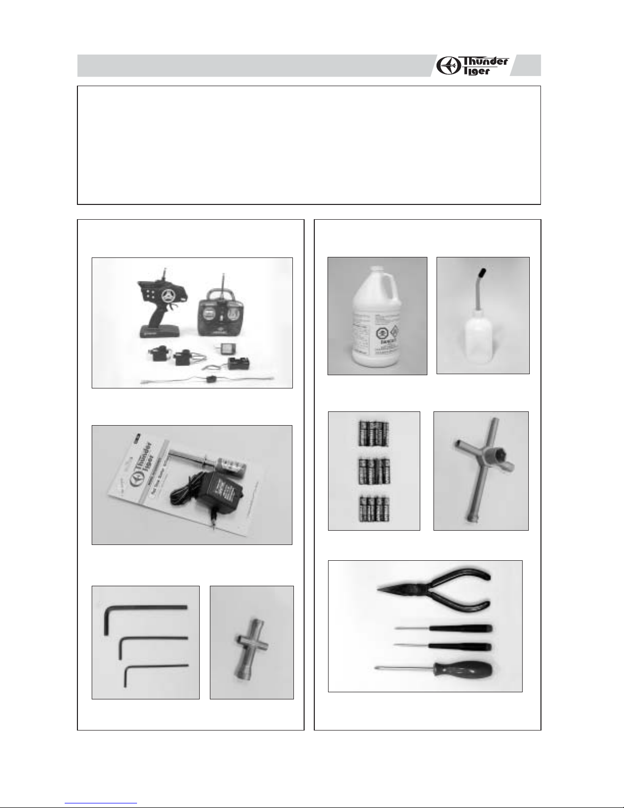
ITEMS SUPPLIED
PURCHASED SEPARATELY
WITH ARTRMODELS
2-Channel, surface radio with 2 high torque servos
ITEMS REQUIRED
Glow Fuel, Methanol
10% to 20% Nitro
5% to 18% Caster / Synthetic Oil
Fuel Bottle
(300cc/600cc)
Glow Starter w/ Charger
HexWrench Set 4-Way Wrench
Alkaline Batteries
(12), AA-size
Philips Screw Drivers, Slotted Screw Driver,
Needle Nose Pliers.
5-Way Wrench
1
Page 3
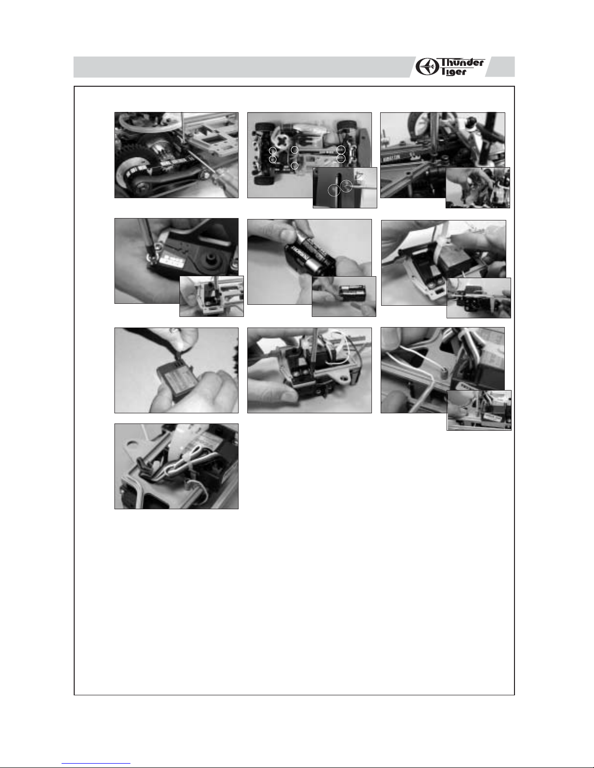
INSTALLING THE RADIO GEAR
skip if already assembled
1
a
c
f
b1
d
g
g
b2
e
h
i
a. Disassemble the roll bar.
b. Remove the 8 screws on the radio plate and two 3*10mm countersunk screws on the chassis.
c.
Install the steering / throttle servos onto the mounts with four tap screws. Notice the orientation of the
throttle / steering servo output shafts
d. Install 4 AAsize alkaline batteries in receiver battery box and connect the receiver battery box to the
receiver switch.
e. Install the battery box below the radio plate and the receiver above the radio plate. Then secure the
two on the radio plate with large zip tie.
f. Properly plug the connectors/wires into the receiver: steering servo connector/wire into channel 1 slot,
throttle servo connector/wire into channel 2 slot, and battery switch connector/wire into battery slot.
g. Install the receiver switch onto the radio plate with its original screws.
h. Thread the receiver antenna / wire through the antenna mount and the antenna tube. Press-fit the
tube onto the antenna mount.
I. Use a small zip tie to organize the excess wiring away from any high temperature or moving parts.
.
2
Page 4
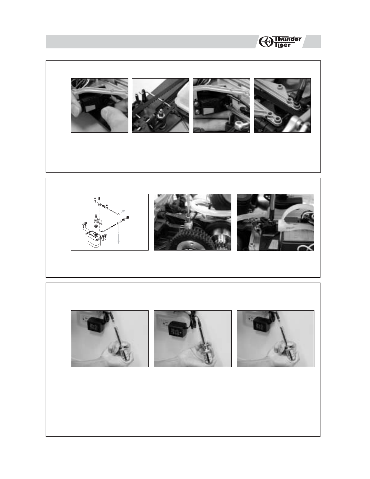
INSTALLING STEERING SERVO LINKAGE
skip if already assembled
2
3
c
a b
a. Install the steering linkage rod onto steering servo horn.
b. Plug the steering linkage rod into the hole on the steering servo saver arm.
c. Install the servo horn onto steering servo output shaft. (In neutral, servo horn should be pointing
straight up, the steering arm should be pointing straight forward.)
d. Reassemble the radio plate onto the car with its original screws.(8 on the plate and 2 on the chassis)
INSTALLING THROTTLE LINKAGE
To engine
a
a. Build the throttle/brake linkages as shown on the diagram.
b. Secure the brake cam lever onto brake cam with set screw.
c. Install the servo horn onto throttle sero output shaft.
carburetor
lever
To brake cam
b
c
skip if already assembled
c
d
d
4
CHARGING THE GLOW PLUG IGNITER
Thunder Tiger Optional Part #2165, 1300MAH Glow Starter w/220V Charger.
Thunder Tiger Optional Part #2166, 1300MAH Glow Starter w/110VCharger.
a b c
a. Plug the charger into an AC outlet, and then pull on the igniter lever to accept the charging adapter.
b. At this point, the small red LED indicator on the charger should light up indicating the charging sequence
is in progress.
c. When the charging complete, pull on the glow plug igniter lever to unplug the glow igniter.
Charge the new glow plug igniter for 16 to 24 hours on the first charge. For subsequent charges, charge
it about 12 hours before next use.
NOTE:
If the igniter gets warm or hot during the charge, unplug the igniter from charger immediately. A warm /
hot igniter means the igniter is overcharged. Overcharging can damage the internal battery in the igniter;
thus, shortening its life.
3
Page 5

PREPARING THE RADIO
5
6
a
a c
a. Install the antenna into transmitter.
b. Check the frequency printed on the transmitter crystal.
c. Check the frequency printed on the receiver crystal, and make sure it matches with the transmitter
crystal. Make sure no one will operate on the same frequency when you are. When there is a radio
glitch, it will most likely be caused by improper crystal, damaged crystal, or people operating on the
same frequency.
RADIO BATTERY INSTALLATION
b
c
a b c
7
a. Install 8AA-size alkaline batteries into transmitter.
b. Undo the large zip-tie, and install 4AA alkaline batteries into receiver battery box.
c. Secure the receiver with batteries back onto the radio plate with the large zip-tie.
RADIO OPERATION
a
a.
When turning radio on, first turn on the transmitter.
b. Then, turn on the receiver. When turning off, first turn the receiver off, then the transmitter off.
c. To reverse the functions of servos, use the small, white servo reverse switches located on side of the
pistol transmitter (or the inset servo reverse switches located at the bottom of the stick transmitter).
To trim the servos on pistol transmitter, use the trim switches on side of the steering wheel (the ST.
trims steering, and the TH trims throttle/brake). On a stick transmitter, the trim levers are located
accordingly around the sticks.
d. For more details, please check the transmitter instruction manual.
b
4
c
Page 6

OPERATING RADIO STEERING FUNCTION
8
abc
a. Checkthe radio steering functions. With the radio transmitter and receiver on, turn the steering wheel/stick
to the left. The front tires/wheels should turn left accordingly. If not, flip the steering servo reverse
switch.
b. Return the steering wheel/stick to neutral. The front tires/wheels should point straight forward. If not,
use the steering trim lever to correct it.
c. Turn the steering wheel/stick to the right. The front tires/wheels should turn right accordingly.
9
OPERATING RADIO THROTTLE / BRAKE FUNCTION
abc
a. Check the radio throttle/brake functions. With the radio transmitter and receiver on, pull the trigger/push
the stick forward. The carburetor should be fully opened and the brake disengaged. To reverse this
function, flip the throttle/brake servo reverse switch.
b. Return the trigger/stick to neutral. The carburetor should be closed to a point where the idle has
been set (see step for ADJUSTING THROTTLE/BRAKE LINKAGE), and the brake still disengaged.
If not, use the throttle/brake trim lever to correct it.
c. Push the trigger/pull the stick backward. The carburetor opening should still be the same at neutral,
throttle spring compressed slightly, and the brake engaged.
5
Page 7

ADJUSTING THROTTLE / BRAKE LINKAGE
10
a
a. To set the throttle/brake linkage, first the radio should be on and neutral; thus, the servo is at neutral
b.
c. With the servo at neutral, loosen the throttle collars. Then, manually closethe carburetor, and set the
ADJUSTING CARBURETOR
b c
position.
With the servo at neutral, turn and adjust the brake adjust knob to a point
engages the brake system, but not yet.
collar (next to the spring) with the spring slightly compressed. Then, set the other collar next to the
linkage pivot.
where the brake lever almost
11
a. To set the carburetor idle (small needle sticking out from the carburetor body), turn the screw as
b. To set the high speed needle (large needle sticking out from the carburetor body), turn the screw as
c. Remove the outer foam from filter and make it moist evenly with a few drops of fuel. If the vehicle
a bc
pictured. Initial idle setting should leave 1mm carburetor gap. Clockwise turn will provide higher idle
(larger carburetor opening), and counterclockwise turn will provide lower idle (smaller carburetor
opening).
pictured. Initial high speed needle setting should be 2.5 turns (close the needle completely, then back
out 2.5 turns). Clockwise turn will provide leaner setting (lower fuel to air mixture), and counterclockwise
turn will provide richer setting (higher fuel to air mixture). Please refer to ENGINE BREAK-IN/SETTING
procedures to properly set the engine.
will be operated in an area with fine dust, use filter oil or caster oil instead of fuel. It is important that
the foam is only moist to trap dirt and allow air passage. With the foam too wet, limited air can pass
through; therefore, limiting engine performance. Finally, make sure the air cleaner boot is securely
fastened with a zip-tie.
6
Page 8

FUELLING
12
a
a. Remove the cap from fuel bottle nozzle.
b. Squeeze the fuel bottle, insert into fuel, and draw fuel into the fuel bottle. The fuel used should be
c. Fill car's fuel tank with glow fuel.
PREPARING THE ENGINE
13
b
methanol based model engine glow fuel (available at hobby shops) with 10% to 20% nitro content
and 5% to 18% caster/synthetic oil content for lubrication.
ba
c
c
c
d e
a. To start an engine, first remove the glow plug.
b. Check the glow plug by plugging it into the glow plug igniter. The glow plug element should light up
brightly. If it lights up dimly, then the glow plug igniter is low (and it needs recharging). If it does not
light up or the plug element looks distorted, then the glow plug is bad (replace with new one). After
checking, reinstall the glow plug.
The glow plug used for this engine can be: Thunder Tiger 9281, McCoy #9 / #59,
Novarossi C4S / C5S / C6S,OS #8 / #A3 / #A5, and Picco P6S / P7S.
c. With the radio off, manually turn the servo to open the carburetor (open throttle).
d. Plug the tuned pipe exhaust tip.
e. Keeping the exhaust tip plugged, pull on the engine's starter. Keep doing it until fuel reaches engine's
carburetor, then pull it 3 more times to prime the engine.
f. Manually return the servo back to neutral.
7
f
Page 9

STARTING THE ENGINE
14
a b
a. Turn on the radio (transmitter first, then receiver).
b. Clip the glow plug igniter onto engine's glow plug.
c. Pull on the engine starter, release, repeat until the engine starts. Throttle maybe required to be opened
Remove the glow plug igniter from engine after engine has started and warmed up. If the engine stops
right after the igniter is removed, the carburetor setting is too rich. Please refer to engine setting section.
If engine starter becomes hard to pull, the engine maybe flooded. To unflood an engine, remove the
glow plug from engine, flip the car upside down, and pull on the starter to release excess fuel. Then,
reinstall the glow plug and repeat the engine starting procedure.
STOCK AND TOE-IN ADJUSTMENT
c
momentarily,but release throttle back to neutral immediately after the engine starts.
15
a. Use the included shock clips to adjust for spring pre-load. Pressing the entire car down, release, and
b. Use a small piece of paper to protect and turn the tie rod. the fronts toe-in angle can be adjusted by
c. The rear toe-in angle is adjusted with the tie rods that connect the rear hubs. To create more/less
a b c
the car should returm to ride height ( indicated on set-up page ). More pre-load clips will produce
higher ride height, and less clips will produce lower ride height. Amount of clips used to front and
rear shocks can be different, but clips should be the same for the left and right.
turning the tie rods that connect the servo savers to the steering blovks. Making longer/shorter the
tie rod, create more/less front toe in.
rear toe-in, turn in/out the front tie rod and turn out/in the rear tie rod. Beware of making equal(but
opposite)adjustments to each tie rod.
8
Page 10

ENGINE BREAK-IN
16
For a new engine (break-in setting), the high speed needle needs to be set as rich as possible. Turn the
high speed needle 1/4 turn counterclockwise from initial setting (2.5 turns from fully closed). Repeat step
15b. Keep doing this until the engine stalls at full throttle, then turn the high speed needle 1/4 turn clockwise.
Run the car in an open parking lot with this rich engine setting for at least 5 tanks of fuel to complete the
break-in process. It is normal for a new engine to stall many times during this time due to the rich setting.
When it does, just restart the engine. After break-in, follow the ENGINE SETTING procedure to set the
carburetor for normal operations.
ENGINE SETTING
Due to different fuel formula, operating elevation, humidity...etc., the engine may/may not operate properly
at initial setting. Please follow the following procedure to achieve proper carburetor setting. Do not perform
this procedure until the engine has been properly broken in.
a. Start the engine.
b. With a running engine, run the car back and foreth in a straight line (full throttle achieved furing each
c. If the exhaust does not reach a high pitch note, turn the high speed needle (long needle, extending from
d. Repeat step 15c until the engine reaches optimum setting (turning in the high speed needle will no longer
e. Toset the idle, turn the idle screw in (higher rpm) or out (lower rpm). Basically, the idle needs to be set
f. To set the low speed needle (inside the throttle lever), the engine needs to be broken in and high speed
g. Repeating step 15b every 10 seconds (1 second full throttle and 10 seconds idle). If the engine rpm at
h. Keep repeating step 15g until the engine rpm drops (goes to idle rpm, then drops a few more rpm after a
passage) in an open parking lot. Repeat and note the sound of the exhaust. Do not hold the throttle
open with car off the ground or the engine connecting rod may break.
carburetor body, pointing up) 1/4 turn clockwise, and repeat step 15b.
have an effect at full throttle and turning out the needle will cause the engine's full throttle rpm to drop a
little). For normal operations, turn the high speed needle 1/4 turn counterclockwise from the optimum
setting.
at the lowest possible point before the engine stalls.
needle needs to be set first.
idle drops after a few seconds and stalls, then turn in the low speed needle (clockwise) 1/4 turn. If the
engine rpm stays the same or goes up at idle, then turn out the low speed needle (counterclockwise) 1/4
turn.
few seconds) but does not stall.
WARNING
Thank you for purchasing a Thunder Tiger Product. Please read all instructions thoroughly before operation.
1. This product is not a toy.It is a high performance model product. It is important to familiarize yourself with the model,
its manual, and its construction before assembly or operation.
2. Do not operate model products in rain, on public roads, near crowds, near airport, or near areas with restricted
radio operation.
3. Always keep fuel away from heat and open flame. Only operate in open, well-ventilated area. Store fuel in cool,
dry area. Keep the fuel bottle cap tightly closed. Clean up any leak or excess fuel before starting the engine.
4. This product, its parts, and its construction tools can be harmful to your health. Always exercise extreme caution
when assembling and/or operating this product. Do not touch any part of model which rotates.
5. Check your radio frequency with the proper operating frequency of the area or country. Always check to see if
there are any modelers operating on the same frequency as your are. Also, check your radio for proper operation
before operating a mode.
6. Improper operations may cause personal and/or property damage. Thunder Tiger and its distributor have no control
over damage resulting from shipping, improper construction, or improper usage.
7. Thunder Tiger assumes and accepts no responsibility for personal and/or property damages resulting from the
use of improper building materials, equipment and operations. By the act of assembling or operating this product,
the user accepts all resulting liability. If the buyer is not prepared to accept this liability, then he/she should return
this kit in new, unassembled, and unused condition to the place of purchase.
9
Page 11

SET-UP
By setting different adjustments on your TS-4N car can help you
obtaining improved steering, traction, and the handling for different
track conditions.
LESS STEERING
FOR SMOOTH TRACK
OIL
450
FOURTH HOLE
FROM THE FRONT
STANDARD
MORE STEERING
LESS STEERING
LOOSEN BELT
TIGHTEN
BELT
MORE
STEERING
STANDARD
FRONT
SOFTER SUSPENSION,
MORE STEERING
STANDARD
STANDARD
STANDARD (3MM)
MORE NARROW, MORE STEERING
WIDER, LESS STEERING
2-SPEED SHIFT POINT ADJUSTMENT
Tighten shift adjust set screw
Shift timing becomes slower
Shifts at higher RPM
STANDARD
LESS STEERING, MORE CLIP
STANDARD,NO CLIP
CAMBER -2˚
More -, more steering
More +, less steering
CASTER 16˚ (max caster, all clips forward)
More +, slow steering / fast exit
More -, quick steering / slow exit
TOE -1˚
Toe-in, ,more straight
Toe-out, quick steering
RIDE HEIGHT 5mm (floor to chassis)
Lower on smooth track surface
Loosen shift adjust set screw.
Shift timing becomes quicker. Shifts at lower RPM
OIL
500
OIL
LESS CAMBER CHANGE
WITH SUSPENSION TRAVEL
FOR TRACK WITH SHARP
LOW SPEED TURNS
REAR
500 MORE TRACTION
(OR USE GREASE)
1000 STANDARD
3000 LESS TRACTION
STANDARD
SOTTER SUSPENSION,
MORE TRACTION
STANDARD
LOOSEN
BELT
LESS CORNER TRACTION
MORE STRAIGHT TRACTION
MORE CORNER TRACTION
LESS STRAIGHT TRACTION
10
FOURTH HOLE
FROM THE REAR
TIGHTEN BELT
STANDARD
CAMBER -2˚
TOE -2˚
RIDE HEIGHT 6.5mm (floor to chassis)
LESS TRACTION
FOR SMOOTH TRACK
STANDARD
LESS TRACTION, MORE CLIP
STANDARD,5MM + 2MM
MORE TRACTION, LESS CLIP
More -, less traction
More +, more traction
More -, more traction / less speed
More +, less traction / more speed
Lower on smooth track surface
OIL
OIL
350-400
400-450
Page 12

1/10 NITRO POWERED 4WD TOURING CAR
No.6166-F
2-CHANNEL RADIO
I
N
PRO-12BXS
C
L
U
Specification
Ǥ WHEELBASE: 265mm
Ǥ FRONT TRACK WIDTH: 200-205mm
Ǥ REAR TRACK WIDTH: 200-203mm
D
E
D
Ǥ WEIGHT (RTR): 1500g
Ǥ POWER UNIT: PRO-12 BXS
DODGE VIPER GTS-R
Features
Ǥ 100% Factory assembled
Ǥ 2-channel radio installed
Ǥ Painted and decaled body
Ǥ Strong, fiberglass reinforced
composite parts.
Ǥ Super low CG, center of gravity
design.
Ǥ Double foam air filter
Ǥ Steel drive cup and dog bones.
Ǥ Roll over bar/ Car handle
Ǥ Color coated springs
Ǥ Full array of option
Ǥ Triple belt, four wheel drive-train.
(4WD)
Ǥ Performance metal manifold &
tuned pipe
Ǥ PRO-12 BXS pull-start engine
Ǥ Full array of body can be
chosen.
Ǥ Fuel tank bottom protector
Ǥ Titanic color anodized chassis,
3mm
Ǥ 2 speed system
Ǥ Metal shock absorbers
Ǥ Full ball bearings equipped
SUBARU IMPREZA WRC
Thunder Tiger Corporation http://www.thundertiger.com
FORD FOCUSPEUGEOT 206
OPEL ASTRA V8
BENZ AMG C32
BMW M3 GT
 Loading...