

Page 1
1
Thunder Tiger Trainer MK II Super Combo/Combo Plus/TRTF (TTR4523)
Distributed in North America by Ace Hobby Distributors, Inc.
116 W. 19th ST, Higginsville, MO 64037
Phone: (660)-584-7121 • www.acehobby.com • email: service@acehobby.com
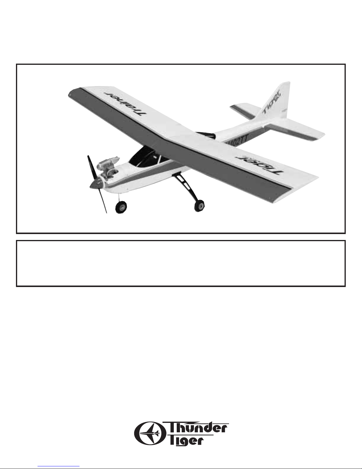
Tiger Trainer MK II
Assembly Manual
Wingspan: 61”
Length: 51”
Wing area: 675 in
2
Weight: 5-5.5lbs
Engine: .40-45
Radio: 4 Channel
Specifications:
Warranty
This kit is guaranteed to be free from defects in material and workmanship at the date of purchase.
It does not cover any damage caused by use or modification. The warranty does not extend beyond the
product itself and is limited only to the original cost of the kit. By the act of building this user-assembled
kit, the user accepts all resulting liability for damage caused by the final product. If the buyer is not
prepared to accept this liability,it can be returned new and unused to the place of purchase for a refund.
99211/JE6131
Notice: Adult Supervision Required
This is not a toy. Assembly and flying of this product requires adult supervision.
Read through this book completely and become familiar with the assembly and flight of this airplane.
Inspect all parts for completeness and damage. If you encounter any problems, call 660-584-6724 for help.
Page 2

2
Notes
Page 3
You have purchased the most pre-fabricated radio control model
airplane on the hobby market. Three versions of this airplane are
available:
TRTF Version: This will require installation of a .40 sized engine and
a four channel radio.
Combo Plus Version: This will require installation of a four channel
radio receiver and battery pack; of course you will need the matching
transmitter. The servos and GP-42 engine are included and installed.
Super Combo: If you have the Super Combo version,it will only take
you a few minutes to get your Tiger Trainer MK II ready for flight plus
no tools or glue are required for completion. Complete radio system
and GP-42 engine are included and installed.
Please read and understand this instruction manual completely
before starting assembly. It will give you an understanding of what you
are about to do and can eliminate the possibility of mistakes. Check
the contents of your airplane for completeness. If any parts are missing, customers in the U.S. and Canada can contact Ace Hobby
Distributors, Inc. for replacement parts at the below address:
Ace Hobby Distributors, Inc.
116 W. 19th ST
Higginsville, MO 64037
(660) 584-6704
NOTE: The batteries in your radio system must be charged
for 24 hours before use. Do not attempt to fly this
airplane without charging the batteries.
3
INTRODUCTION
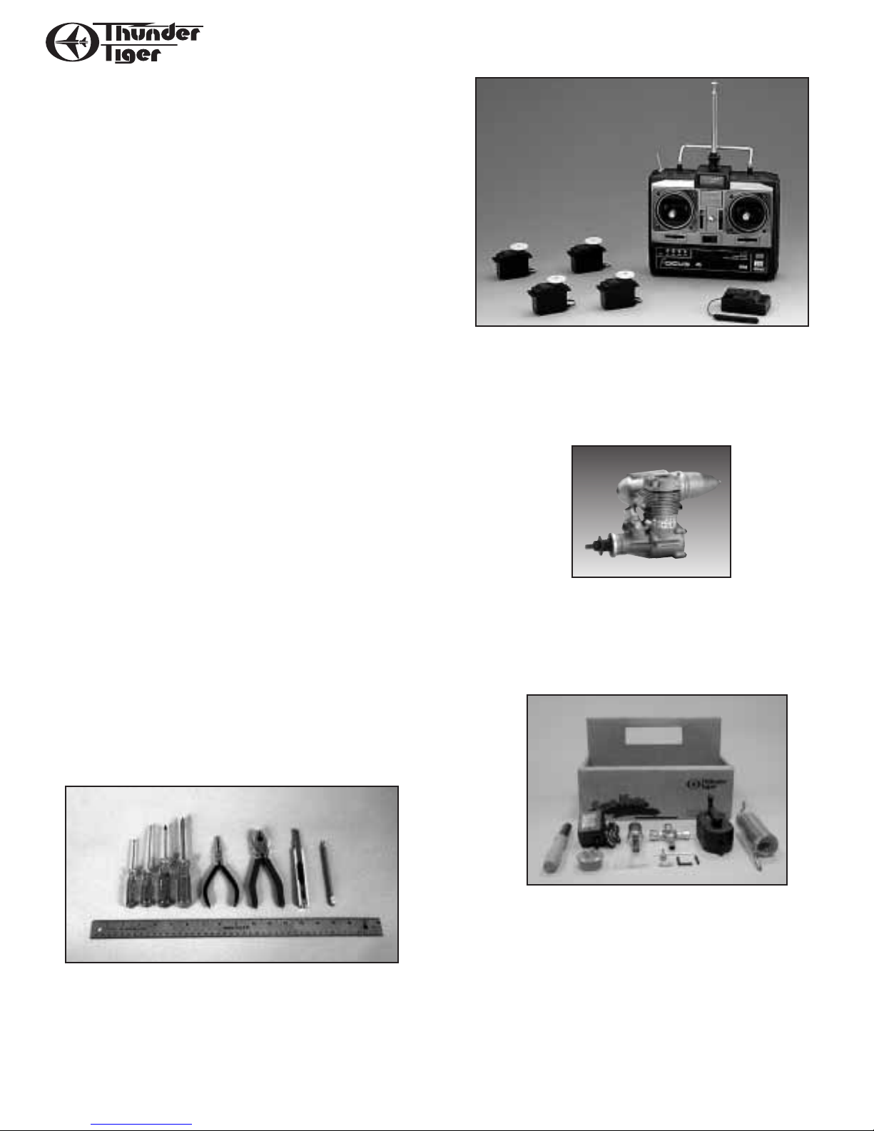
You will need the following to complete your Tiger Trainer MKII:
Super Combo: Nothing; no tools, no glue.
Combo Plus: Four Channel Transmitter, Receiver, and Battery Pack
TRTF: Four Channel Radio w/4 servos, Engine (.40-.46 cu. in.),
Household tools.
NEEDED FOR FLIGHT:
You will need “support” equipment to fly your MK II. This
includes model engine fuel (10% nitro recommended),a fuel pump or
bulb with fuel line, a glow plug clip and battery (or glow starter), electric starter or “chicken stick.”
Thunder Tiger makes a product called the “Side Kick” which contains all of the support equipment you need (except fuel) in a convenient tote box. You may want to consider this economical package if
you are just starting out.
Adhesives:
Instant setting Cyanoacrylate adhesive (thin CA)
Tools:
Model knife
Small and medium screwdrivers
Long nose pliers
Drill and drill bits
Fine felt tip pen and soft lead pencil
R/C System:
A 4-channel radio with standard servos is required for the TRTF version. Transmitter, receiver, and battery pack required for Combo Plus
Version. Radio furnished in Super Combo.
Engine:
The Thunder Tiger GP-42 is the ideal engine for this airplane.This quietrunning engine is easy to start, requires no special break-in period,
is very easy to maintain and will last for years.
Propeller appropriate for engine type and preferred performance.
Page 4
4
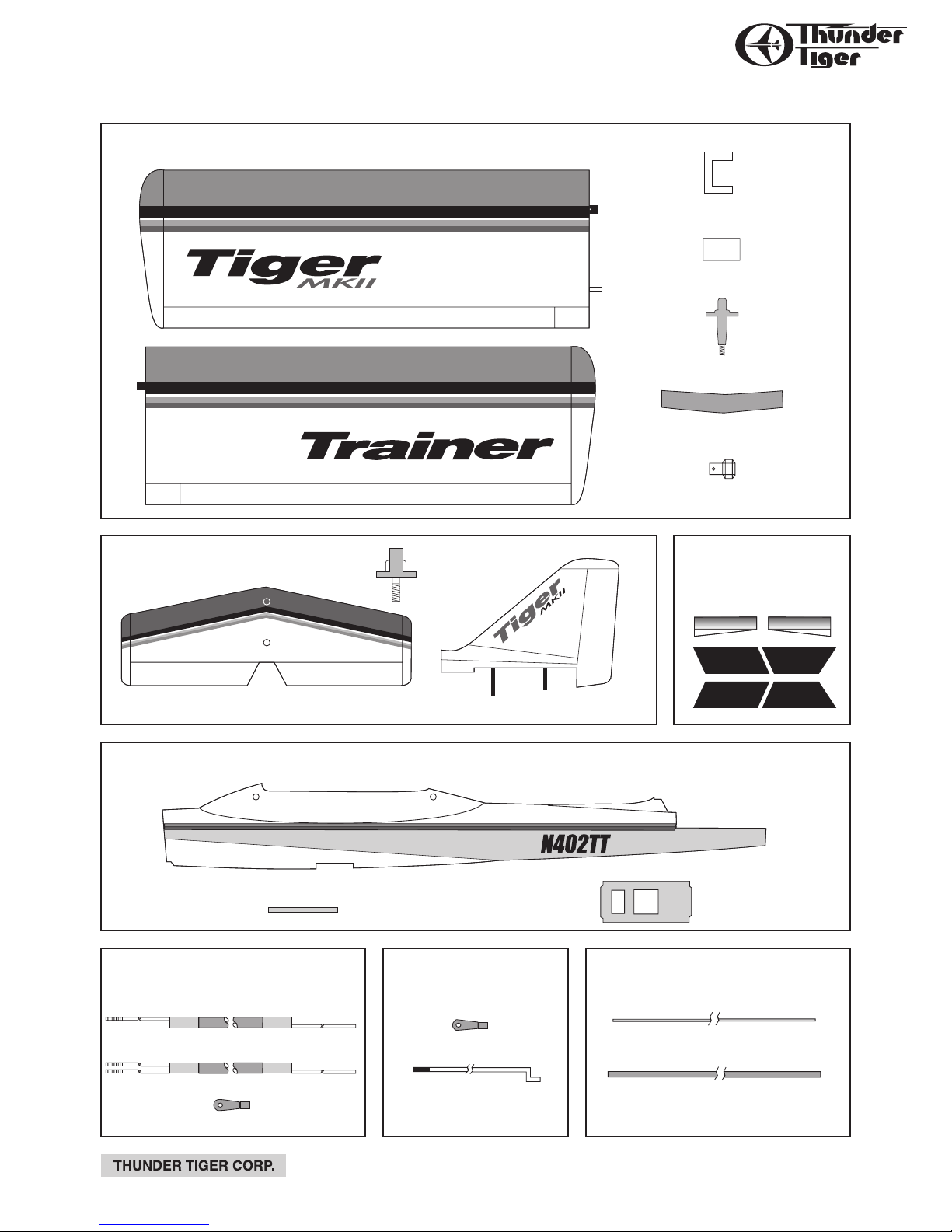
PARTS DRAWINGS
1999.10 V.1
ORDER BY BAG NUMBER ONLY
INDIVIDUAL PARTS NOT AVAILABLE
Left Wing (1)
AS6052 Wing Set
AS6053 Tail Feathers
AS6054 Fuselage Set
PE0005 Decal Set
0.05" Metal Pushrod
Plastic Guide Tube (2)
PE0577 Forward Pushrods
AS6056
Aileron Pushrods
Clevis (2)
Threaded Rod (2)
Aileron Servo Tray (1)
Plywood Wing Joiner
Torque Rod Horn (2)
Wing Dowels (2)
Fuselage (1)
Servo Tray (1)
Stabilizer/Elevator (1)
Vertical Fin/Rudder (1)
Right Wing (1)
AS6055 AFT Pushrods
Rudder Pushrods (1)
Clevis (3)
Retaining Screw (1)
Retainning Screw (2)
Wing Protector (2)
Stab Pushrod (1)
Page 5

5
PARTS DRAWINGS
1999.10 V.1
ORDER BY BAG NUMBER ONLY
INDIVIDUAL PARTS NOT AVAILABLE
Straight
Nipple (1)
Cap (1)
PE0004 Hardware Set
3mm x 3mm
Set Screw (1)Push Rod Connector (2)
2mm Hex Nut (2) Allen Wrench (1)
3263 Fuel Tank Set
Silicone Tube (1)
Clunk (1)
90˚ Nipple (1)
(Not Used)
Rubber Stopper (1)
300 c.c. Tank (1)
3150 Control Horn Set
2mm x 12mm Screw(6)
Wood Screw
2.6mm x 8mm (4)
3296 Wheels Set
(sold in pairs)
Wheel (3)
3162 Hinge Set
Point Style Hinges (15)
Windshield (1)
PE0002 Window Set
Rear Window (1)
3mm Hex Nut (2)
Spinner (1)
Self-Tapping Screw
3mm x 12mm (2)
3222R Spinner Set
Spinner Back Plate (1)
AS6050 Nose Gear Set
Steering Arm Collar (1)
Wheel Collar (2)
Steering Arm (1)
Nose Gear Wire (1)
Screw
3mm x 5mm (3)
PE0003 Cowl Set
Left Cowl (1) Right Cowl (1)
Control Horn (3) Nut Plate (3)
3102 Adjustable Engine Mount
Engine Mount Plate (1)
Beams (2, left/right)
Screw
3mm x 15mm (4)
6/32 x 18mm
Screw (6)
6/32 Blind Nut (6)
Nose Gear Bearing (1)
300 c.c.
AS6051 Main Landing Gear Set
AS6057 Decal Set
Main Landing Gear
4x32mm Screw (2)Mounting Plate (1) 4mm Locknut (1)
3x18mm
Self-Tapping Screw (4)
Page 6
6
ASSEMBLY
I. IF YOU HAVE A SUPER COMBO:
Skip to Section IV: ASSEMBLY on page 9.
II. IF YOU HAVE A COMBO PLUS:
Before performing the final assembly steps, it is necessary to
install your receiver and battery pack in the airplane, following your
radio system’s instructions.
The connectors on the servos and switch harness are compatible
with Futaba “J” style radios. If you are using a different type radio,you
will need to either modify the connectors or obtain adapters. The
small polarizing ear on the servo and switch harness connectors can
be carefully trimmed off with an Xacto knife to allow it to be plugged
into JR,Hitec, and Airtronics (Sanwa) “Z” receivers. If you have an older
style Airtronics (Sanwa) radio, you MUST obtain adapters because the
polarity is opposite all other brand radios.
Remember to wrap the receiver and battery pack in at least 1/4”
thick foam. Route the receiver antenna out the rear of the wing opening; if you wish, drill a 1/16” hole in the rear window for an antenna
exit. MAKE SURE you don’t put any strain on the antenna wire coming out of the receiver; have some sort of strain relief. Also, make sure
you don’t lengthen or shorten the antenna; performance will be
affected. Continue the antenna wire to the top of the fin and hook
with a straight pin and a small rubber band. Any excess can just trail
out the back of the plane.
Skip to Section IV: ASSEMBLY on page 9.
III. IF YOU HAVE THE TRTF VERSION:
A. Install the Main Gear
Referring to Sec. IV, Step A, secure the Main Gear in place. It will
help stabilize the fuselage as you work on it.
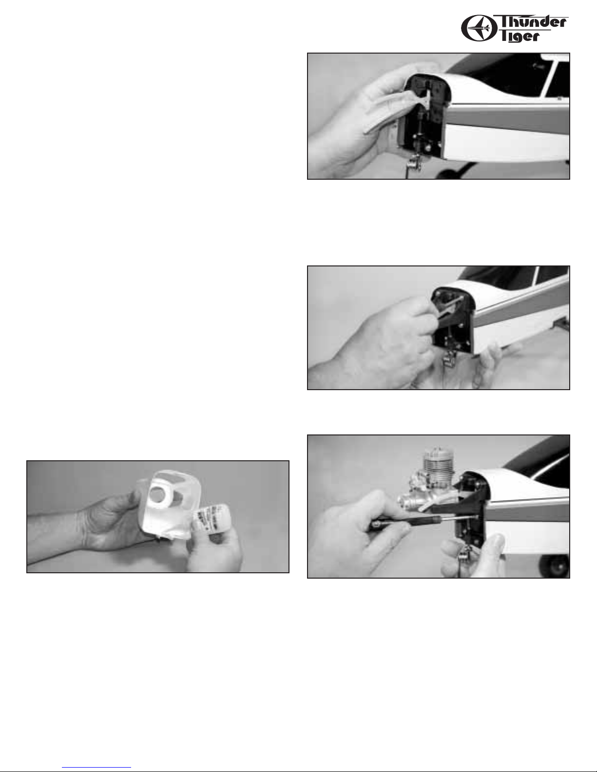
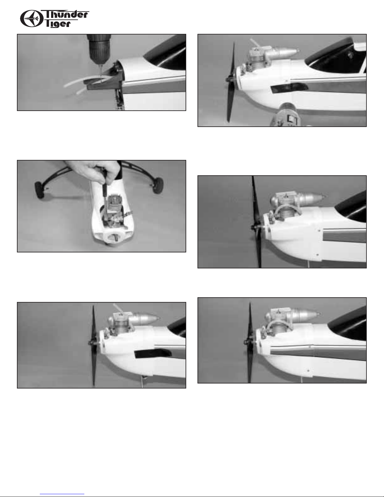
B. Engine/Cowl Installation
1. Test fit the two halves of the injection molded cowl together.
Trim away any molding “flash” that prevents a good fit. With the two
halves pressed tightly together,sparingly apply thin CyA glue along the
joint. Prevent runs by applying most of the glue from the inside.
2. Locate the three black nylon engine mount parts and the four
3X16 mm bolts. Position the engine mount plate on the firewall by
threading the fuel line coming from the fuel tank through the large
hole in the middle of the plate. Next, slip the bottom bracket on the
plate over the top of the nose gear assembly. You should now be able
to position the plate against the firewall and lined up with the four
mounting holes.
3. Place the left and right engine mount beams in position and
loosely hold in place with the four 3X16 mm bolts. The reinforcing
‘web’ on both beams should face upward and outward as shown.
4. Set your engine in place and adjust the engine mount beams so
they are centered on the plate and almost touching both sides of the
engine crankcase. Securely tighten the four bolts.
Page 7
7
ASSEMBLY
5. Position the engine so the thrust washer is 4 1/4” from the firewall. Making sure the engine is square on the mount, mark the four
hole positions on the beams with a pencil. Remove the engine and
drill 3/32”holes at each of the marked locations,making sure the holes
are perpendicular with the beams. Run the 3 X 15 mm self-tapping
engine mount screws in and out of these holes to establish threads.
6. There is a ‘z’ bend on the end of the throttle linkage. It connects the engine’s throttle arm to the linkage. Hook the ‘z’bend into
the throttle lever’s innermost hole, slip the cowl over the engine
cylinder head and move this assembly into position on the engine
mount (you will probably have to remove the needle valve). Secure
the engine with four 3 X15 mm self-tapping screws.
7. Install the muffler onto the engine. If needed, trim the cowl
for at least 1/8” clearance around the muffler and needle valve. Place
the spinner backplate on the engine prop shaft and temporarily secure
it with the prop, prop washer,and prop nut. Adjust the cowl until it is
centered behind the spinner with about 1/8” clearance between the
backplate and the cowl. Use a couple pieces of tape to hold it in place.
8. Drill four 1/16” holes through the cowl and into the fuselage
about 1/4” deep. Locate these holes about 3/8” forward of the rear
edge of the cowl. The bottom holes should be about 1/2”from the bottom edge of the fuselage and the upper hole should center in the yellow pin-stripe. Secure the cowl with the four 2X10 mm wood screws
furnished.
9. Route the fuel and vent lines to their correct fitting. The top
line is the vent line and goes to the pressure tap on the muffler; the
bottom line is the fuel line and goes to the carburetor.
10. Apply the cowl decals to the cowl, lined up with the stripes
on the fuselage. Note there is a right and a left.
Page 8

8
ASSEMBLY
11. Complete the spinner installation. Loosen the prop nut and
rotate the spinner backplate so the two little posts rest against the
prop trailing edge; then tighten the prop nut. Use the two special
screws furnished to secure the spinner nose cone onto the backplate.
12. Secure the wheel onto the nose gear using the wheel collar
and set screw furnished. Make sure it turns freely.
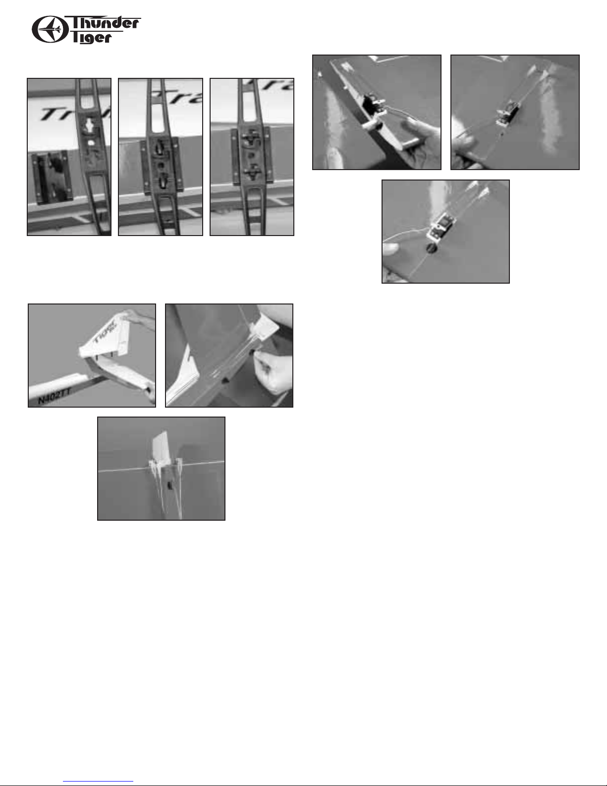
C. Install the Radio
1. Refer to your radio system’s instruction manual for complete
installation instructions. Prepare your servos by putting the rubber
grommets in the mounting ears. Install three of the servos in the fuselage’s servo tray, positioning them as shown. As you install each servo,
pass the connector end of the cable through to the forward compartment so you can plug into the receiver later. Drill 1/16” pilot holes
before securing the servos using the screws furnished with your radio.
Next,cut a hole in the side of the fuselage and drill holes to mount the
switch, using the switch cover as a template. Mount the switch.
2. Hooking your servos to the linkage is done according to the above
drawing. The pushrods are secured to
the servo wheels or arms with “z”
bends. (Note: the elevator pushrod has
two rods exiting the tail; the rudder
pushrod has only one.)
The throttle pushrod and the
nosegear pushrod are connected to the
servos with “EZ” connectors. The “EZ”
Connector barrel is attached to the
servo wheel/arm with the furnished
nut. The pushrod is secured in the barrel with a set screw and Allen
wrench, which makes the pushrod length easily adjustable.
3. Install your aileron servo in the tray that is glued into the left
wing half as shown. Linkage to the ailerons is done via two pushrods
with a “z” bend on the servo end and a nylon clevis on the aileron
torque rod end. Hook up the “z” bend ends of the two aileron
pushrods to both sides of the servo wheel/arm and secure the
wheel/arm to the servo. Snap the clevis onto the nylon torque rod
horn on the left aileron. You will attach the clevis to the right aileron
torque rod horn when the wing is joined.
4. Plug the servos into the proper receiver outlets. Wrap the
receiver and battery pack in at least 1/4”thick foam. Route the receiver antenna out the rear of the wing opening; if you wish, drill a 1/16”
hole in the rear window for an antenna exit. MAKE SURE you don’t
put any strain on the antenna wire coming out of the receiver; have
some sort of strain relief. Also, make sure you don’t lengthen or shorten the antenna; performance will be affected. Continue the antenna
wire to the top of the fin and hook with a straight pin and a small rubber band. Any excess can just trail out out the back of the plane.
Z-bend
to throttle arm
receiver
to nose gear
throttle servo
elevator servo
EZ connector
pushrod
to elevator
to rudder
rudder servo
allen wrench
set screw
barrel
nut
servo wheel or arm
Page 9
9
ASSEMBLY
IV. ASSEMBLY
A. Secure the main landing gear
The main landing gear is secured by a “twist ‘n lock” system.
Simply put the landing gear into position on the belly of the airplane
then rotate the thumb tab 1/4 turn clockwise until it snaps into the
groove.
B. Attach the tail
The vertical fin and horizontal stabilizer attach to the fuselage
with the two thumb screws furnished. Insert the plastic posts that
protrude out the bottom of the fin through the sleeves in the stabilizer as shown,then slip them into the sleeves in the rear of the fuselage.
Secure the tail assembly to the fuselage with the two special thumb
screws, making sure they are firmly tightened and the tail assembly is
securely attached to the fuselage.
Snap the pushrod clevises into the holes in the control horn as
shown.
C. Join the wing
Insert the dihedral brace into one wing half. Slip the other wing
half into place, lining up both the plastic joiner blocks and the rear
alignment dowel as the wing comes together.
Secure the connection with the special tapered thumb bolt,
screwing it in until it is snug to the bottom of the wing. Do not overtighten!
Snap the servo linkage clevises into the holes in the nylon horns
that are pre-installed on the aileron torque rods.
D. Charge the batteries
Refer to the Radio’s Instruction Manual.
Note that there is an unoccupied two-wire connector coming
from the receiver switch. It is your charging jack. The switch must be
OFF in order to charge the batteries. Plug the Receiver output from
your radio system charger into this connector. Plug the Transmitter
output into the charge jack on your transmitter. Now plug the
charger into a wall outlet. The two LED indicator lights should be lit,
indicating that current is flowing into the batteries. If not, double
check that connections are secure and both switches are off.
The first time you charge your batteries,leave them on charge for
24 hours. For all subsequent charges, charge the batteries overnight
(14-16 hours).
Page 10

E. Radio Check
Note that there is an unoccupied three wire cable coming from
your receiver. This is the receiver output for the aileron servo in the
wing. Plug the aileron servo into this cable’s connector and put the
wing in its place on the fuselage. Hold it in place with a few rubber
bands. Turn on your transmitter and then the receiver. Move the sticks
and observe the motion of the control surfaces on the airplane.
Referring to Drawing Four, make sure the direction of travel of
the control surfaces matches the proper direction of stick movement.
If it is opposite, refer to your radio system instructions on how to
reverse the servo travel.
Also make sure the surfaces are in neutral when both the stick
and the trim lever are in the center. If not, unsnap the clevis from the
control horn and screw it in or out until neutral is achieved.
Also make sure the amount of movement (throw) is proper. If the
throw is too much,move the clevis out on the control horn. If it is two
little, move the clevis in on the control horn. You will have to re-neutralize the surface when you’ve made a throw adjustment.
F. Balance Check
With the wing on the airplane, use your two index fingers to suspend the model in the air. Locate your fingers 3 3/4” back from the
leading edge of the wing,about 4” out from the fuselage. At this point,
a right angle is formed where the leading edge and the center balsa
sheeting ends. You can feel this point with your finger tips.
The plane should hang level or slightly nose down at this point.
If the tail drops, you need to redistribute or even add weight to the
nose until the plane balances. You can move the receiver battery pack
10
RADIO CHECK
to above the fuel tank if you need to. If the plane’s nose drops dramatically, add a little weight to the tail as a remedy. Stick-on weights
are available at your hobby shop for this purpose.
V. PRE-FLIGHT
A. Charge your batteries if it has been over two weeks since
they were charged last.
B. Rubber band the wing on:
Plug the aileron servo into the aileron cable coming from the
receiver. Making sure the excess cable is down inside the fuselage,
attach the wing to the fuselage using the rubber bands furnished. Use
eight rubber bands to secure the wing. Use two on both the right and
left side, then crisscross two more from the right front to the left rear
and crisscross the final two from the left front to the right rear.
C. Radio Check
MAKE SURE NO ONE IS OPERATING ON YOUR FREQUENCY
(Channel number). Any flying field has rules to govern frequency
usage. Make sure you abide by them.
Refer to your radio instruction manual for the proper ground
range you can expect from your system. Perform this range check
each flying session.
Move the transmitter sticks and verify that all control surfaces are
moving in the proper direction relative to stick motion. Make sure all
are working smooth and nothing is loose or binding.
Make sure all servo wheel/arm screws are in place. It is a common problem for a servo wheel to fall off a servo because the screw
was not re-installed after an adjustment!
Check the engine and engine components; make sure all screws
are tight.
D. Fuel-up the engine
Remove the fuel line from the engine’s carburetor. Plug your fuel
pump or bulb into this line. Pump fuel into the tank until you see it
coming out the line that is going to the engine’s muffler. (You may
want to remove this line from the muffler to prevent fuel from getting
into the muffler.)
high throttle killidle
3-3/4"
1/2"
down elevator up elevator
7/8"
right rudder right aileron
3/8"
1/2"
3/8"
pick up model at arrows
Page 11

11
FLYING
NOTE: If you get these fuel lines mixed up, look down into the
engine compartment and observe the fuel tank. The fuel line going
to the lowest part of the tank is the “fuel” line;it goes to the carb. The
other line that goes to the upper part of the tank is the “vent” line; it
goes to the muffler. Realize that the fuel system is a “closed loop” system; the back pressure in the muffler maintains a positive fuel flow
to the engine. Any air leaks in the system will degrade performance.
E. Start the engine
Carefully read and understand the Engine Operating Instructions
furnished so you are familiar with the operation of a model airplane
engine. As it comes in your Super Combo or Regular Combo Plus, it
should be ready to start as installed. Simply “choke” the engine, hook
up a hot 1.2V-1.5V battery to the glow plug, and flip the prop with a
“chicken stick” or an electric starter. Follow the break-in procedures
in the Engine Operating Instructions for the first 4 or 5 flights.
VI. FLYING
It is strongly recommended that you have a qualified instructor
teach you to fly. Without training, the likelihood of having a mishap is
increased greatly, just as if you were flying a real airplane. Also, there
are several good computer simulators on the market that can help
teach you the skills necessary for success. Talk to your hobby dealer
about instructors available in your area plus the simulators that he has
available.
You should join the Academy of Model Aeronautics. This membership is required by most clubs plus it provides liability insurance in
the case of an accident. Contact the AMA at:
5151 East Memorial Dr., Muncie, IN 47302
GETTING ORIENTED
We recommend that you find a large smooth and clear surface to
practice taxing your airplane around in before you try a take off.
To taxi, you only need to use the rudder stick. At the slow speeds
encountered during taxing, the elevator and ailerons will not be
effective. The first and most important thing to remember when controlling model aircraft is:the model controls are set up to operate as if
you were sitting in the cockpit of the model. This means that when
you pull back (down) on the elevator stick the nose of the plane will
go up. Moving the rudder stick to the right will “yaw”the plane to the
right and moving the aileron stick to the right will “roll” the plane to
the right. Pretty simple right? Well, not quite. Since you are really standing on the ground and not sitting in the plane,this is how the controls
work when you are facing the same direction the plane is flying.The
problem is that when the plane is flying towards you, the rudder and
aileron controls seem reversed to the inexperienced pilot.This is the
reason we recommend that you practice taxing around in a large open
area to try and get used to the control reversal.
During your first few flights, try to face the direction that the plane is
flying and looking over your shoulder as needed.This makes it a little
easier to pretend that your sitting in the cockpit.
FIRST FLIGHT
When you are comfortable with the controls,you should be ready
for your first flight. Go over the Pre-Flight Check List one more time
for good measure and taxi out to the runway (hopefully with an experienced pilot by your side). Point the model directly into the wind and
gradually increase the throttle to full throttle. As the model starts
rolling forward it may try to turn to the left due to the engine torque.
Apply enough right rudder to keep the plane rolling relatively straight
into the wind. If you built the model with right thrust, this tendency
may not be noticeable.As the plane picks up speed, the right rudder
input can be reduced.
Once the plane reaches flying speed, it will probably try to fly by
itself.If the grass seems to be impeding takeoff,a very slight amount of
“up” elevator can be applied, but it is very important that you do not
apply too much up elevator too early or the plane will stall and roll
over into the ground.
As the plane becomes airborne, reduce the “up” elevator and
allow the plane to pick up flying speed while gently gaining altitude.
Once a safe flying speed and altitude has been obtained, feel free to
turn the airplane back toward the flying field. Make all control inputs
smoothly and gradually so you can see the effect they have on the
plane.A small amount of “up” elevator will need to be applied to keep
the plane level during turns.You should be able to reduce the throttle
to about 1/2 throttle for normal cruising flight which will reduce the
flying speed and give you more time to think about what is going on.
You will find that once airborne, you can fly the plane with only the
aileron and elevator sticks.This is perfectly fine and will make it much
easier for you to learn.
If the plane has a tendency to turn, roll, climb, or dive, you can
adjust the transmitter trims to correct this. On your first flights, it
might be a good idea to have an experienced pilot make the adjustments for you while you fly the plane.
If you get disoriented or the plane gets out of control,simply take
your hands off all the controls and allow the plane to stabilize. Clear
your head and try to picture yourself sitting in the cockpit.Then input
Page 12

12
the required control movements to get the plane back on the correct
flight path. If you run out of time or flying space and realize the plane
is going to hit something (ground, tree, etc), pull the throttle back to
idle and pull the elevator stick back about half way.This will reduce
the speed of the plane and minimize the damage sustained.
When you are ready to land, do a couple of slow fly-bys at a safe
altitude to get familiar with the plane’s slow-flying characteristics.An
important factor to remember here is that you should regulate your
altitude with the throttle not the elevator as you might expect.Practice
raising the nose of the plane slightly with a touch of “up” elevator and
then using the throttle to regulate the plane’s altitude.When you are
ready to land,fly downwind past the runway.When the plane is a hundred yards or so downwind, reduce the throttle to almost an idle and
turn 90 degrees towards the runway. Fly straight for a second or two
until the plane is almost even with the runway.Turn 90 degrees again
and fly directly toward the runway using the throttle to govern how
quickly the plane is descending. Keep the nose of plane up slightly
with the elevator and allow the plane to fly gently onto the runway.
Do not try to stretch the glide path without increasing the throttle or
the plane may stall.
VII. POST-FLIGHT
Turn off all switches and if you are done for the day, de-fuel the
tank. Clean-up your plane with some spray cleaner (such as 409) and
paper towels. While you are cleaning the plane up, inspect it for damage...check the prop for dings or chips. Spray some WD40 on and in
the engine for protection.
If you want, you can disassemble your airplane for easy transportation. Disassembly is as simple as assembly. You can remove the
landing gear, break the wing down in two pieces, and remove the tail.
Just make sure you don’t lose any of the hardware, especially the special thumb screws.
When you get home, ALWAYS charge your batteries overnight,
even if you only flew once.
VIII. SAFETY PRECAUTIONS
1. Wear safety glasses when starting and running all model engines.
2. Model engine fuel is very flammable and the flame is very dan-
gerous because it is almost invisible! Do not smoke or allow
sparks, high heat or other flames near the fuel.
3. Do not run model engines inside a garage or other closed room
as they give off large amounts of deadly carbon monoxide gas.
4. Do not run model engines around gravel, sand or other loose
debris.These materials will be ingested through the carburetor
and can also be kicked up by the prop.
5. Always stay behind the propeller when the engine is running.
Make all engine adjustments from behind the engine. Under no
circumstances should you allow your face or body near the
plane on rotation of the propeller when the engine is running.
6. Do not allow loose clothing or other loose objects close to the
prop.
7. To stop an engine, cut off the fuel or air supply to the engine.
Do not throw rags or other objects into the prop to stop the
engine.
8. Do not touch the engine or muffler during or right after it has
been running–It gets very hot!
IX. REPAIR
In the event of a minor mishap, the MKII usually can be repaired.
Begin by completely cleaning the area being repaired with alcohol to
remove any oil residue.
• Balsa components can be glued back together with CA glue.
• If you need to repair around the firewall/engine area,use epoxy.
• The plastic parts can be taped back together,deleted, or rebuilt out
of balsa.
• Use Carl Goldberg Models’ Ultracote® to patch the covering film.
 Loading...