

Page 1
JE6911
Assembly Instructions
Warranty
Thunder Tiger Corp. guarantees this model kit to be free from defects in both material and
workmanship at date of manufacture. This warranty does not cover any components
damaged by use or modification, and in no case shall Thunder Tiger's liability exceed the
original purchase price of the kit. Thunder Tiger also reserves the right to change or
modify this warranty without notice.
Since Thunder Tiger Corp. has no control over possible shipping damages or construction
by the modeler, no liability can be assumed nor accepted for damage resulting from the
use by the user or the final user-assembled product. By the act of using this userassembled product, the user accepts all resulting liability. If the buyer is not prepared to
accept this liability, he should return this kit in new and unused condition to the place of
purchase for a full refund.
1
No.4582
16
POST-FLIGHT CHECK
SAFETY PRECAUTIONS
1.Wear safety glasses when starting and running all
model engines.
2.Model engine fuel is very flammable and the flame is
very dangerous because it is almost invisible! Do not
smoke or allow sparks, high heat or other flames near the
fuel.
3.Do not run model engines inside garage or other closed
room as they give off large amounts of deadly carbon
monoxide gas.
4.Do not run model engines around gravel, sand or other
loose debris. These materials will be ingested through
the carburetor and can also be kicked up by the prop.
5.Always stay behind the propeller when the engine is
running. Make all engine adjustments from behind the
engine. Under no circumstances should you allow your
face or body near the plane on rotation of the propeller
when the engine is running.
6.Do not allow loose clothing or other loose objects close
to the prop.
7.To stop an engine, cut off the fuel or air supply to the
engine. Do not throw rags or other objects into the prop to
stop the engine.
8.Do not touch the engine or muffler during or right after it
has been running-It gets very hot!
9.If you hear any unusual noises while your plane is flying,
land at once and determine the problem before returning
to the air. Control surface flutter, which often emits a lowpitched Buzz, can quickly destroy an airplane and
should not be ignored. Flutter is usually caused by sloppy
control surfaces and is generally relatively easy to cure.
If you get disoriented or the plane gets out of control,
simply take your hands off all the controls and allow the
plane to stabilize. Clear your head and try to picture
yourself sitting in the cockpit. Then input the required
control movements to get the plane back on the correct
flight path. If you run out of time or flying space and
realize the plane is going to hit something (ground, tree,
etc), pull the throttle back to idle and pull the elevator
stick back about half way. This will reduce the speed of
the plane and minimize the damage sustained.
When you are ready to land, do a coupler of slow fly-bys
at a safe altitude to get familiar with the plane's slowflying characteristics. An important factor to remember
here is that you should regulate you altitude with the
throttle not the elevator as you might expect. Practice
raising the nose of plane slightly with a touch of “up”
elevator and then using the throttle to regulate the
plane’s altitude. When you are ready to land, fly
downwind past the runway. When the plane is a
hundred yards or so downwind, reduce the throttle
almost an idle and turn 90 degrees towards the runway.
Fly straight for a second or two until the plane is almost
even with the runway. Turn 90 degrees again and fly
directly toward the runway using the throttle to govern
how quickly the plane is descending. Keep the nose of
plane up slightly with the elevator and allow the plane to
fly gently onto the runway. Do not try to stretch the glide
path without increasing the throttle or the plane may
stall.
1.Be sure that both the transmitter and receiver switches
are turned off.
2.Drain all excess fuel from the tank. Fuel left in the tank
for extended periods can “gunk up” the tank, fittings and
carburetor.
3.Clean the plane with paper towels and a light-duty
spray cleanser. Keeping your plane clean will make it last
longer and keep it looking nice.
4.Put a few drops of after-run or light oil in the carburetor
and turn the prop over a few times (without the glow plug
ignited) to distribute the oil throughout the engine.
5.Inspect the prop and replace it if any chips or cracks
are found.
6.Inspect the entire plane for covering tears, new dings
and dents, loose screws and connect connectors and
any other wear and tear.
7.Use a voltmeter to check the receiver battery voltage.
If it is low, you now know not to fly so long next time. If it
is still high, you should be able to fly a little longer next
session.
POST-FLIGHT CHECK LIST
Page 2
INTRODUCTION
Tools-Model assembly can be much easier if the proper
tools are used. Therefore we have included in our
checklist to above, a complete listing of all the tools we
used to assemble our prototype models. As you will
notice, many household tools can be utilized during
construction.
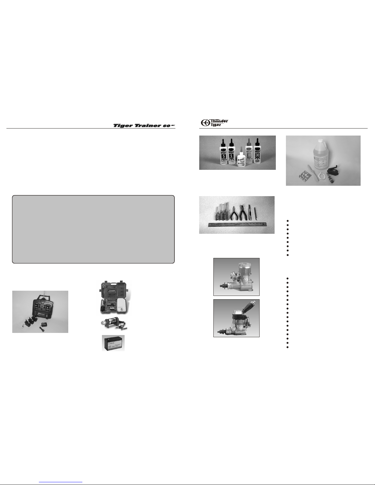
Engine The Thunder Tiger GP-61 and F-75S are the ideal
engines for this airplane. These quiet running engines are
easy to start, require no special break in periods, are very
easy to maintain and will last for years.
Flight Equipment There are several “support” items
that you will need to purchase in order to get your engine
running and your plane in the air. These are listed at the
bottom.
ITEMS NEEDED
Introduction
A checklist is also provided on the next page which
will make shopping for these items easier.
OTHER ITEMS REQUIRED FOR
ASSEMBLY
Radio - A 4- channel radio with 4 standard servos is
required. Most lower priced 4-channel radios only
come with three standard servos so you may need to
purchase the fourth servo separately.
Comprehensive Items Needed Check List
4-Channel Radio with 4 Standard Servos
5-Minute Epoxy (4 ounces or so)
30-Minute Epoxy (4 ounces or so)
“Thin” Instant Adhesive (1/2 ounce)
“Thick” Instant Adhesive (1/2 ounce)
Hobby Knife and Blades
Epoxy Mixing Sticks and/or Brushes
Sandpaper (150 grit)
Masking Tape
Rubbing Alcohol
Paper Towels
Ruler
90 Degree Triangle
Waxed Paper
Fine-Point, Felt-Tip Pen
Misc. Household Tools
Drill and Bits (1/16", 5/64", 9/64”)
Flight Equipment Needed Check List
Foam Rubber Padding for the Radio
Stick on Lead Strip for Balancing the Plane
3 or 4 Props (see engine instructions)
10%-15% Glow Fuel
Fuel Pump or Bulb
Electric Starter or “ Chicken Stick”
Glow Starter
Extra Glow Plug(s)
Silicon Tubing
Adhesives- You will need two types of adhesives for the
Tiger Trainer - Epoxy and Instant ( cyanoacrylate )
adhesives. We recommend that you purchase both 5minute and 30-minute epoxy to cut down on assembly
time, but you can get by with only 30-minute epoxy if time
is no important. You will also need a small bottle of both
"Thick" and "Thin" instant adhesive.
All of us at Thunder Tiger want to thank you for choosing the best looking, easiest building and best flying ARF trainer
available, the Tiger Trainer 60 MKII.The kit features state-of-the-art engineering that provides quick and easy
assemble of a strong, yet lightweight airplane that will give you an enjoyable and educational experience.
To gain the most from this airplane kit, it is important that you read the instructions thoroughly and then follow them
exactly. This instruction manual has been written with a novice modelers in mind, but includes many hints and
modeling tips that even experienced modeler can benefit from. We strongly suggest that you read through the
construction sequence and eliminate many questions you might have if you did not read the manual prior to starting the
actual construction.
The first thing you should do before beginning assembly is to check the contents of your kit against the parts list on
pages 4 and 5. If any parts are missing, contact your dealer or authorised Thunder Tiger Distributors immediately for
replacement.
32
No.9060
No.9802
Introduction...........................................................................................2
Other Items Required..........................................................................2
Items Need Check List ............................................................................3
Parts List..............................................................................................4-5
Pre-assemble Notes............................................................................6
Wing..........................................................................................7
Fuselage..............................................................................................7-8
Install the Engine................................................................................8-9
Install Fuel Tank..........................................................................................9
Tail....................................................................................................10-12
Install The Radio..........................................................................................12-13
Balance & Final Assembly Flight.................................................14-16
TABLE OF CONTENTS
Carry Master-Thunder
Tiger offer a complete
organizer of field
equipment. All you
need is included.
No.1263-65
ACCESSORIES
12V DC Starter- Provides high
torque starting power to start
your outboard engine.
Sealed Battery- 7Ah 12V
Sealed Battery.
No.2674
No.2624
GP-61
F-75S
Page 3
N
6
0TT
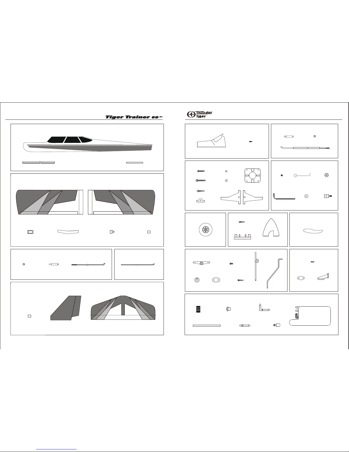
Fuselage (1)
PARTS DRAWINGS
AS6600 Aileron Pushrod
PARTS DRAWINGS
AS6595R Fuselage
AS6595L
AS6596R Main Wing
AS6596L
AS6599 Forward Pushrod
54
Dowel (2)
Left Wing (1)
Right Wing (1)
Aileron Servo Tray (1)
Wing Joiner (1)
Aileron Torque Horn (2)
CA Hinge (10)
Tig
e
r
CA Hinge (9) Fin/Rudder (1)
Stab./Elevator (1)
Clevis (2) Pushrod (2)
Plastic Guide Tube (2)
0.05" Piano Wire (2)
AS6597R Tail Feathers
AS6597L
2 1/4” Spinner (1)
AS6598 Windshield
3103 Adjust Engine Mount
AS6602 Hardware Set
AS6604 Spinner
AS6606 Control Horn
AS6605 Landing Gear
3266 Fuel Tank
3x3mm
Set Screw (2)
Allen Wrench (1)
Push Rod
Connector (2)
2mm Washer (4)
2mm Hex Nut (2)
3x12mm Self
-Tapping Screw (2)
Backplate (1)
Nose Gear Mount (1)
Engine Mount Plate (1)
Beams (L/1, R/1)
AS6601 Rudd/Elev. Pushrod
AS6603 Wheels
Wheel (3)
Pushrod (2)
Clevis (2)
2.3x15mm Screw (4)
Nut Plate (2)
Control Horn (2)
Main Gear (2)
Nose Gear (1)
3x5mm Screw (1)
3x12mm Self Tapping Screw (4)
Steering Horn (1)
Collar (8)
Mounting Strap (2)
420cc Fuel Tank (1)
Clunk (1)
Cap(1)
90-degree Nipple (1)
Rubber Stopper (1)
Silicone Tube (1) Straight Nipple (1)
2.3x8mm
Wood Screw (10)
Windshield (1)
4x24mm Screw (4)
Silicon Ring(2)
Silicon Ring(2)
4x25mm Wood Screw (4)
3x20mm Screw (2)
AS6607 Rubber Bands
Rubber Bands(8)
4mm Washer (4)
3mm Washer (2)
Switch Pushrod (1)
Tiger Sport
Page 4

WINGPREASSEMBLY
PRE-ASSEMBLY NOTES
1. If you are not an experienced R/C pilot, plan to have a
fully competent pilot check your completed model and
help you with your first flights. Even though we have tried
to provide you with a very thorough instruction manual,
R/C models are rather complicated and an experienced
modeler can quickly check over your model to make sure
your first flights are successful.
2. Please assemble your model exactly according to these
instructions. Do not attempt to modify or change the Tiger
Trainer in any way as doing so may adversely change
its flying characteristics.
3. Before you begin, please check the entire contents of
this kit against the parts drawing make sure that no parts
are missing or damaged. This will also help you to
become familiar with each component of your plane. If
you find that any of the parts are either missing or
damaged, please contact your dealer immediately for
replacement.
Note: Your dealer cannot accept kits for return if
construction has begun.
4. Trial fit each part before gluing it in place. Make sure
you are using the correct part and that it fits well before
assembling. No amount of glue can make up for a poor
fitting part.
WING ASSEMBLY
76
1.Before gluing the two wing halves, trail-fit the wing
joiner into the wing panels. If it is not easy to slide into
the wing, sand it until it will.
2. With 30-minute epoxy, liberally coat all sides and
edge of the wing joiner and slip it into one wing half.
Now coat the inside edge of the center wing rib where it
will join to the other wing half. This is called the “root” of
the wing.
Join the two wing halves and firmly press wing panels
together. Wipe off any excess epoxy with a paper towel
and rubbing alcohol. Make sure the two panels are
accurately aligned with each other. You may hold
together with several strips of masking tape.
3. Place the servo tray centered over the cutout in the
bottom of the wing. Mark around the servo tray with a
marker.
4. Remove the tray, and use a sharp knife to score the
covering material where marked. Remove the covering
material to expose the wood underneath. Use thick CA
or epoxy to glue the servo tray securely in place.
5. You may apply tape(not furnished) to center wing joint.
Start at the servo tray and work around the wing. Gently
pull on the tape while pressing it down onto the wing to
slightly stretch the tape into place and provide a smooth
seam.
6. To hinge the ailerons, remove the clear tape that
holds one of the ailerons in place. Pull the aileron off the
wing, revealing five hinges. Center these hinges in their
slots in the AILERON and secure them with THIN CA,
letting it wick into the joint. Glue both sides of the hinge.
7. When the glue has set, re-install the aileron onto the
wing. Hint: While flexing the aileron one way or the other
and while holding the wing up on its front edge, carefully
wick CA into the slot where the hinge goes into the wing.
Do so on both sides of the hinge. After the glue has set,
tug on the aileron at each hinge location to make sure
the hinges are securely glued in place. Also, make sure
the aileron is free to move up and down.
Note: you can remove any residue from the tape with
alcohol. Set your wing aside, for now.
FUSELAGE ASSEMBLY
8. Insert the throttle tubing first. It runs along the right
side of the fuselage and goes from the up corner of the
firewall back through the right hole in the first former and
then through second and third formers. Glue it securely
in place with thick CA.
9. Same way to the nose gear tubing. Insert the tube
through the first former and second former. Glue the tube
in place with thick CA.
Page 5

FUSELAGE
ENGINE
98
INSTALL THE MAIN GEAR
10. Locate the main landing gear channel in the bottom
of the fuselage. Use a sharp hobby knife to remove any
covering from the slot. You might lightly coat the
exposed wood in the landing gear slot with 5-minute
epoxy to prevent the wood from becoming fuel soaked.
11.Position the two plastic landing gear straps across
the landing gear strut. Using a felt tipped pen, mark the
location for the four landing gear mounting strap holes.
Drill the four mounting holes as marked with 5/64” drill
bit. Secure the mounting strap by four 2.3X12 screws.
12. Install the wheels onto the main gear using the
supplied two wheel collars and 3X5mm set screws.
Make sure the wheel rotates freely.
INSTALL THE ENGINE
13.Attach the engine mount plate, both mounting beams
and the nose gear bearing to the fire wall using the 4
X24mm screws provided. Make sure the mounting beam
“webs” are near the outside of the mount. It is not
necessary to fully tighten the four engine mount screws
at this time. Also temporarily install the nose gear, using
the steering arm to secure it. A special collar and
Phillips head screw inserts in the steering arm, which
secures it to the nose gear. The screw should contact
the “flat” that is ground into the nose gear. Note the
orientation of the coil on the nose gear. The nose wheel
is secured with two wheel collars and phillips head
screws.
14.Set the engine on the mount and adjust the beams, if
necessary, so that they are almost touching both sides
of the engine crankcase and are centered in relation to
the engine mount. Now position the engine so that the
front of the thrust washer is approximately 5” from the
firewall.
15.Remove the engine and drill a 3.5mm(9/64'') hole at
each of the four marks you just made. “Break-in'' the
mounting holes by inserting a 4X20mm wood screw into
each hole without the engine in place. A drop of oil in
each hole may help the screws thread in easier.
16. Using either Z-bend pliers or a regular pair of pliers,
make a “Z” bend in one end of one .050'' piece of wire.
Slide it into the throttle linkage tube.
Hook the “Z” bend onto your engine's throttle arm and
move the engine into position. You may have to bend
some jogs in the wire to prevent binding of the linkage.
Screw the engine in place on the mount.
17.In a similar fashion, make a “Z” bend in the remaining
piece of .050'' music wire for the nose gear steering
arm. You will need to remove the nose gear so the
steering arm is loose and “Z” bend can engage the outer
tube and re-install the nose gear. Make sure the 3X5mm
screw firmly tightens on the “flat” that is ground on the
nose gear. Rotate the nose wheel back and forth a few
times to make sure it rotates freely without binding. You
may need to bend the pushrod wire slightly to eliminate
any binding in the pushrod. If the alignment between the
nose gear bearing and the engine mount seems to be
causing some binding, loosen the mounting screws and
adjust the mounts until it rotates smoothly.
INSTALL THE FUEL TANK
18.Assemble the fuel tank by first cutting the silicone
tube to 3-3/4’' in length. Press the straight plastic nipple
into the rubber stopper (Saliva will ease insertion.) Now
slip the silicone tubing onto the nipple and insert the
metal clunk into the other end of the tubing. Insert this
assembly into the tank (clunk first) and securely tighten
the threaded cap on to hold everything together.
19. Attach two 7’' standard fuel lines (not furnished) to
both the fuel outlet nipple and the vent nipple on the tank.
Slide the fuel tank (cap end first) into the front of the
fuselage, threading the fuel lines through the oblong
hole in the firewall. The tubing coming from the tank's
fuel outlet (center) goes to the carb and the tubing from
the vent (upper) goes to the muffler's pressure fitting.
Trim the length as needed. The tank fits tightly in the
former.
20.Trim the windshield along with the molded cutting line
with curved scissors. Apply the windshield decal.
Page 6

TAILSTAILS
1110
21. Put the windshield on the front fuselage. It is held in
place with eight 2.3X8mm wood screws. You will need to
drill a 1/16'' pilot hole for each screw first. Next install
the wing dowels.
INSTALL THE TAIL GROUP
22.Remove the elevator and rudder and glue the hinges
into the control surfaces using the same technique
outlined for the ailerons.
23. Trim away the covering from the slot and pushrod
exit hole at the rear of fuselage where vertical fin and
horizontal stab go.
24.Use ruler to decide the center of stab and make
marks. With the main wing centered on the fuselage,
position the horizontal stab. Draw lines at both sides of
stab.
25.Remove the stab and fin from the fuselage and use a
hobby knife to carefully score the covering material
where marked. Make the score approximately 1/16''
inside the lines you drew. It is very important that you do
not press hard enough to cut into the wood itself or the
stabilizer may fail in flight. Just score the covering and it
will peel away nicely.
In a similar fashion, remove the covering material on the
vertical fin.
26. Glue the stab and fin to the fuselage with epoxy,
keeping the stab and fin in position as diagram shown.
o
90
A
A'
A=A'
The fin is perpendicular to the stab. Both stab tips to the
main wing are equal from the rear view (A=A').
27.The rudder and elevator pushrods have already
been pre-assembled at the factory. Insert the rudder
pushrods which is bent at the thread end , thread end
first, into the fuselage and exits the slot on the top of the
rear fuselage. Locate the clevis, thread the clevis onto
the threaded end at least 1/4'' in length.
28.Locate the control horns and 2X20mm screws. Snap
the clevis onto the control horns. Now position this horn
onto the Rudder in such a way that the nyrod runs
straight and the holes in the control horn are in line with
the hinge line of the stabilizer. Mark the location of the
control horn mounting holes on the elevator. Next, drill
5/64'' holes where marked.
29.Cut the control horn as photo shown.
30. Carefully cut a hole with hobby knife at the tail as the
elevator pushrod exit.
31.Use control horn as template and drill 5/64'' holes
with the control horn in line with the hinge line of
elevator and right at the pushrod exit.
Page 7

RADIO
1312
CONTROL THROWS
INSTALL THE RADIO
33. Mount three servos on the servo tray which is
already installed in your fuselage. Note their orientation
in the photo. Follow your radio's instruction manual and
make sure you use the grommets, eyelets, and screws
furnished with your radio. Drill 1/16'' pilot holes for the
mounting screws before insertion.
34.Now it is time to hook the servos up to the control
surface. Install the pushrod connector onto the
outermost hole in the rudder servo arm as shown. To do
so, remove the servo arm from the servo place the
pushrod connector so the threaded portion exits the
bottom of the servo arms. Secure in place using a 2mm
washer and nut. You may need to apply tiny glue to keep
nut in place but make sure connector rotates freely.
35. Do the same procedure on throttle servo arm.
Ensure that the hole for the pushrod wire is parallel to
the length of the fuselage. Align the pushrod tube with
the servo. The pushrod tube should not extend all the
way to the servo as this would cause the pushrod to
bind during operation. To shorten the pushrod tube,
remove any excess length with a sharp hobby knife
accordingly. Insert the pushrod wire through the
pushrod connector. Secure in place using a 3mm set
screw. Carefully adjust the control throws as page 13
and 14 shown.
36.Hookup to the ailerons is via a nylon horn that is
threaded onto the torque rod that is already installed in
the wing. Screw the horn down until there is about 1/16''
of threads exposed above the horn. Use threaded rods
with clevises on the end for the linkage. Apply a small
piece of silicone and slide it onto the clevis. Bend a “Z”
bend on the servo end of the rod at the proper length so
you have neutral aileron when the servo is centered.
37.Mount the switch on the servo tray. Drill a 2mm hole
on the fuselage for the switch extension rod to control
the switch.
38. Wrap your receiver and battery with packing foam
which is available at local hobby shop. Install the
receiver and battery in the front of the servo tray.
Receiver is near the servo tray and battery is far from
the servo tray as shown.
Drill a 1/16'' hole through the fuselage side, about one
inch behind the switch mount. From the inside out,
thread the receiver antenna through this hole. You may
want to tie a knot in the antenna 3'' or 4'' from the
receiver to act as a strain relief. Attach the end of the
antenna to the top of the vertical fin with a small #10
rubber band and a T-pin. Maintain only a slight amount
of tension on the antenna wire.
39.Correctly install the prop in front of the spinner
backplate using the engine prop washer and prop nut.
Note that the spinner backplate has two little posts that
must be rotated up against the prop blade before the
spinner will fit on. Rotate the prop counter clockwise
until it is vertical when it is against the engine's
compression stroke. Securely tighten the prop nut using
a prop wrench or correctly fitting wrench. It is not a good
idea to use pliers when tightening the prop nut! Attach
the spinner to the spinner backplate using the two
3x12mm self tapping screws provided.
Make sure the direction of servo moves correctly. If not
switch the reversing switch on the transmitter. If the
control surface does not move far enough, either move
the pushrod out farther on the servo horn or move the
clevis in farther on the control horn. If the control
surface moves too much, either move the pushrod in on
the servo horn or move the clevis out farther on the
control horn. Adjust the control throws as following
suggested.
CONTROL THROWS
Elevator-High Rate
1/2",12mm
1/2",12mm
Elevator-Low Rate
3/8",9.5mm
3/8",9.5mm
Aileron-High Rate
5/8",18mm
5/8",18mm
Aileron-Low Rate
1/2",12mm
1/2",12mm
Rudder
7/8",22mm
7/8",22mm
1/4” 6mm
Nose Wheel
32. Mount the control horn with 2X20mm screws. Insert
the elevator pushrod with clevis threaded on. Apply a
small piece of silicone and slide it onto the clevis. Then,
snap the clevis on the outmost hole of control horn.
40. Place the wing onto the fuselage and tuck the
aileron extension into the radio compartment. Use at
least 8(eight) rubber bands to hold the wing in place. A
good method of doing this to apply 2 rubber bands from
the left front dowel to the left rear dowel, 2 from the right
front dowel to the right real dowel . 2 from the right front
dowel to the left rear dowel and the remaining 2 from
the left front dowel to the right rear dowel .
Congratulations ! Now your Tiger Trainer 60 is
ready to fly. Please do the radio movement check as
well as the balance and control throw before you go to
fly. All Thunder Tiger staffs hope you enjoy flying your
new Tiger Trainer 60.
1/4” 6mm
Page 8

1514
PRE-FLIGHT CHECKSBALANCE
With the radio system still on, move the throttle trim
lever up the middle. This should open the carburetor
barrel up slightly(1/32"-1/16") and allow the engine to
idle satisfactorily. To shut the engine off from the
transmitter, simply move the throttle stick and trim lever
all the way down. Now move the throttle stick up and
watch the carburetor barrel. It should reach full open at
the same time the stick reaches it end point. If it does
not follow the instructions below. If the barrel does not
open all the way, move the pushrod in one hole in the
carburetor throttle arm. If the carburetor barrel reaches
full open and makes the servo " hum" very early in the
transmitter sticks movement, move the pushrod
connector in on the servo horn( to a hole that is closer to
the center of horn).
Grasp the throttle pushrod, and while looking at the
opening in the top of the carburetor, adjust the pushrod
until the throttle barrel( inside ) is all the way closed.
Tighten the setscrew in the pushrod connector to secure
the pushrod in that postion. Cut off the excess throttle
pushrod approximately 1/2" past the EZ connector.
Barrel Closed
Open Slightly
Barrel Open
N
60TT
Tiger
IMPORTANT- Do not attempt to fly your model before
completing this every important section. A model that is
not properly balanced will be unstable and could cause
serious damage and /or injury.
The balance point for this model is 3” behind the leading
edge of the wing. Measure this distance and mark it on
both sides of the fuselage right under the wing. With
your model fully assembled but without fuel, pick it up
with your index fingers at each of the two balance marks
you made earlier. If balanced properly, the plane will
hang horizontally. If the plane hangs with the tail down,
then you need to add (or redistribute) some weight in the
nose. Usually the plane will either balance or hang
slightly tail heavy. The easiest cure for a tail-heavy plane
is to move the receiver and battery forward as far as
possible. If the plane hangs nose down, then you need to
add some weight to the tail. Stick-on lead weights are
available from your hobby dealer that will make adding
weight a simple task. Once you have everything
positioned as necessary, wrap your receiver and battery
pack in 1/4'' or 1/2'' thick foam for protection.
BALANCING YOUR PLANE
If you are an experienced pilot, some of the following
text will not apply to you. Simply disregard references
to “your first flights”.
LOCATE A GOOD FLYING SITE
Generally, the best place to fly your model is at AMA
(Academy of Model Aeronautics) charactered club field.
Your local hobby dealer can tell you if there is such a
club a club in your area or write the AMA for information.
It is also a good idea to join this organization before
flying your model since they offer liability insurance that
can protect you if your model causes damage or injury
to others.
If there is not a chartered club field in your community,
you will need to find a large area free of obstructions,
which has a smooth grass or asphalt surface to be used
as a runway. For safety's sake, it should be located well
away from houses, building schools, power lines and
airport. If you will be flying within 6 mile of an airport,
you should check with the airport manager before flying
your model.
PRE-FLIGHT
Academy of Model Aeronautics
5151 East Memorial Dr.
Muncie, In 47302-9252
The batteries are the heart of your radio system. Make
sure you have fully charged batteries! With
rechargeable batteries, follow the manufacturers
instructions to make sure the batteries are fully charged,
especially the first time the radio is used.
If your radio uses dry cells, make sure your batteries are
in new condition. You have a lot of money invested in
this project so it is not worth the risk of using old
batteries.
A NOTE ON BATTERIES
You should perform these checks before each flying
session.
1. Check all control surfaces for possible looseness or
deterioration.
2. Check all screws, rubber band, clevises, nuts and all
other connectors to make sure they are securely
fastened.
3. Check which radio frequencies are being used. Do not
turn your radio until absolutely sure you are the only one
operating on that frequency.
4. Check for proper operation of all control surfaces.
5. Check the level of charge in both the transmitter and
receiver batteries before flying.
6. Range check the radio both with and without the
engine running! Follow the radio manufacturer's
instructions for this.
PRE-FLIGHT CHECKS
Learning to fly a radio control aircraft can be very exiting,
but it is important that you thoroughly understand the
basics of flight and controls before you attempt your first
flights. Therefore, we highly recommend that you seek
the expertise of an experienced instructor pilot for the
first few flights. He (or she ) can get you in the air much
more smoothly than trying everything yourself for the
first time.
FLYING
GETTING ORIENTED
We recommend that you find a large smooth and clear
surface to practice taxing your airplane around in before
you try to take off. To taxi, you only need to use the
rudder stick. At the slow speeds encountered during
taxing, the elevator and ailerons will not be effective.
The first and most important thing to remember when
controlling model aircraft is: the model controls are set
up to operate as if you were sitting in the cockpit of the
model. This means that when you pull back (down) on
the elevator stick the nose of the plane will go up.
Moving the rudder stick to the right will “yaw” the plane
to the right and moving the aileron stick to the right will
“roll” the plane to the right. Pretty simple right? Well, not
quite. Since you are really standing on the ground and
not sitting in the plane, this is how the controls work
when you are facing the same direction the plane is
flying. The problem is that when the plane is flying
towards you, the rudder and aileron controls seem
reversed to the inexperienced pilot. This is the reason
we recommend that you practice taxing around in a large
open area to try and get used to the control reversal.
During your first few flights, try to face the direction that
the plane is flying and looking over your shoulder as
needed. This makes it a little easier to pretend that your
sitting in the cockpit.
FIRST FLIGHT
When you are comfortable with the controls, you should
be ready for your first flight. Go over the Pre-Flight
Check List one more time for good measure and taxi out
the runway (hopefully with an experienced pilot by your
side). Point the model directly into the wind and
gradually increase the throttle to full throttle. As the
model starts rolling forward it may try to turn to the left
due to the engine torque. Apply enough right rudder to
keep the plane rolling relatively straight into the wind. If
you built the model with right thrust, this tendency may
not be noticeable. As the plane picks up speed, the right
rudder input can be reduced.
Once the plane reaches flying speed, it will probably try
to fly by itself. If the grass seems to be impeding take off ,
a very slight amount of “up” elevator can be applied, but
it is very important that you do not apply too much up
elevator too early or the plane will stall and roll over into
the ground.
As the plane becomes airborne, reduce the “up” elevator
and allow the plane to pick up flying speed while gently
gaining altitude. Once a safe flying speed and altitude
has been obtained, feel free to turn the airplane back
toward the flying field. Make all control inputs smoothly
and gradually so you can see the effect they have on the
plane. A small amount of “up” elevator will need to be
applied to keep plane level during turns. You should be
able to reduce the throttle to about ½ throttle for normal
cruising flight which will reduce the flying speed and
give you more time to think about what is going on. You
will find that once airborne, you can fly the plane with
only the aileron and elevator sticks. This is perfectly fine
and will make it much easier for you to learn.
If the plane has a tendency to turn, roll, climb, or dive,
you can adjust the transmitter trims to correct this. On
your first flights, it might be a good idea to have an
experienced pilot make the adjustments for you while
you fly the plane.
3”
 Loading...