

Page 1
WARRANTY
Thunder Tiger Model Company guarantees this model kit to be free from defects in both material and
workmanship at date of manufacture.This warranty does not cov er any components damaged by use or
modification and in no case shall Thunder Tiger’s liability exceed the original purchase price of the kit.
Thunder Tiger also reserves the right to change or modify this warranty without notice.
Since Thunder Tiger Model Co. has no control over possible shipping damages or construction techniques and materials used for construction by the modeler, no liability can be assumed nor accepted for
damage resulting from the use by the user of the final user-assembled product.By the act of using this
user-assembled product, the user accepts all resulting liability.If the buyer is not prepared to accept this
liability, he should return this kit in new and unused condition to the place of purchase for a full refund.
Assembly Instructions
Tiger
Bipe 40
Item No. 4557
JE6351.V1
Page 2
2
INTRODUCTION
INTRODUCTION
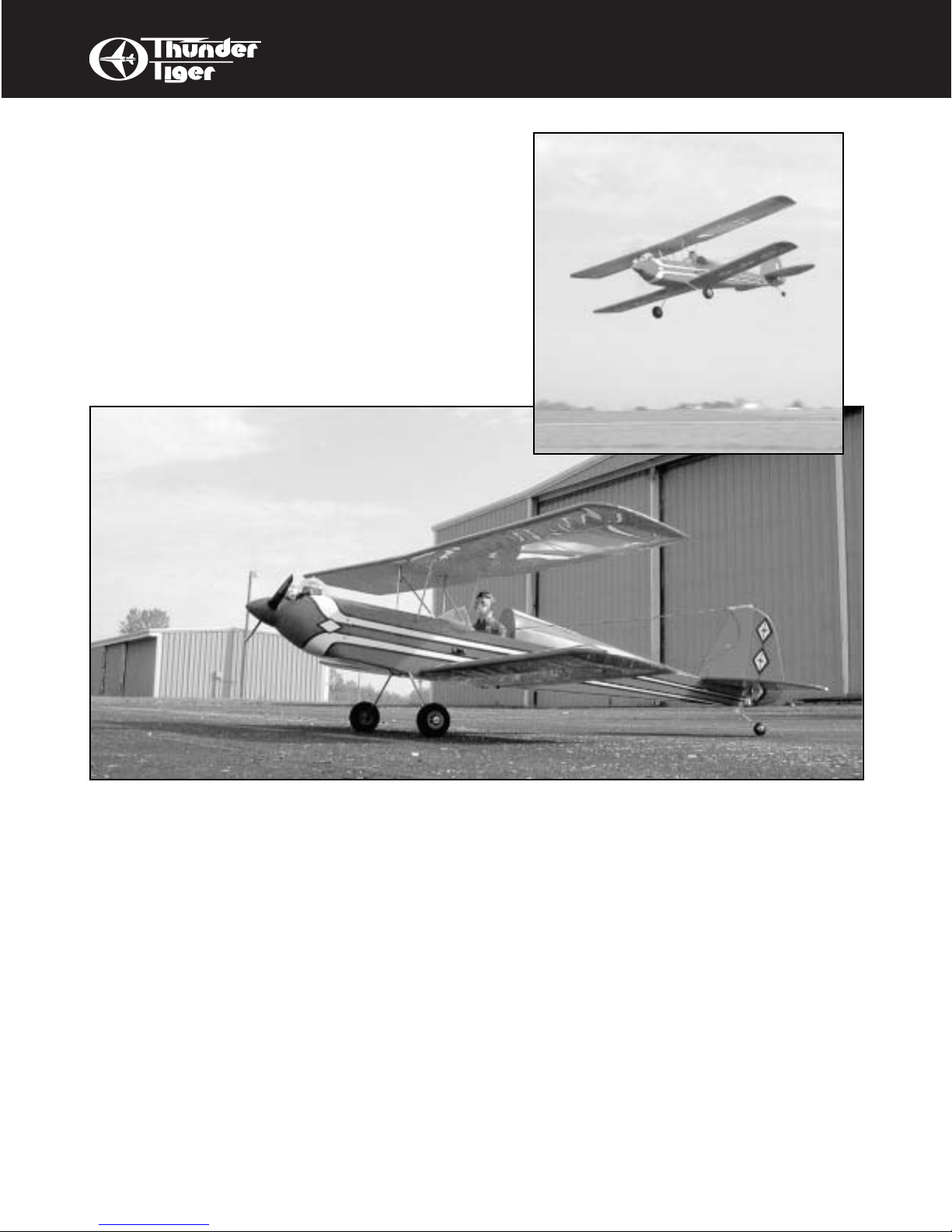
All of us at Thunder Tiger want to thank you for choosing the best looking, easiest building and best
flying ARF biplane available, the Tiger Bipe 40. This kit features state-of-the-art engineering that provides quick and easy assembly of a strong, yet lightweight air plane that will give you an enjoyable and
thrilling experience.The Tiger Bipe will allow you to enjoy model airplanes the way they were meant to
be: with two wings!
To gain the most from this airplane kit, it is important that you read the instructions thoroughly and then
follow them exactly.We strongly suggest that you read through the instructions completely before beginning construction.This will give you a good idea of the construction sequence and eliminate many questions you might have if you did not read the manual prior to starting the actual constr uction. Due to the
nature of this design, this airplane is not intended for a beginner’s first model and the instructions are
written with this in mind. We assume you have a working knowledge of airplane and radio terminology.
The first thing you should do before beginning assembly is to check the contents of your kit against the
parts list on pages 4 and 5. If any parts are missing, contact your dealer immediately for replacement.
Customers in the United States and Canada may contact Ace Hobby Distributors at 116 W. 19th
Street, Higginsville, MO 64037 (660) 584-6704 for replacement parts. Under no circumstances can a
kit be returned if assembly has already been started.
Introduction . . . . . . . . . . . . . 2
Other Items Required . . . . . . . . . 2
Items Need Check List . . . . . . . . . 3
Parts List . . . . . . . . . . . . . 4-5
Pre-Assembly Notes
. . . . . . . . . . 6
Wing
. . . . . . . . . . . . . . . . 7
Landing Gear . . . . . . . . . . . . 8
Tail . . . . . . . . . . . . . . . 9-10
Engine. . . . . . . . . . . . . . . 11
Tank. . . . . . . . . . . . . . . . 12
Install the Radio. . . . . . . . . . 13-14
Cowl
. . . . . . . . . . . . . . . 15
Flight
. . . . . . . . . . . . . . 16-17
Safety . . . . . . . . . . . . . . . 18
A checklist is also provided on the next page
which willmake shopping for these items easier.
TABLE OF CONTENTS
OTHER ITEMS REQUIRED
FOR ASSEMBLY
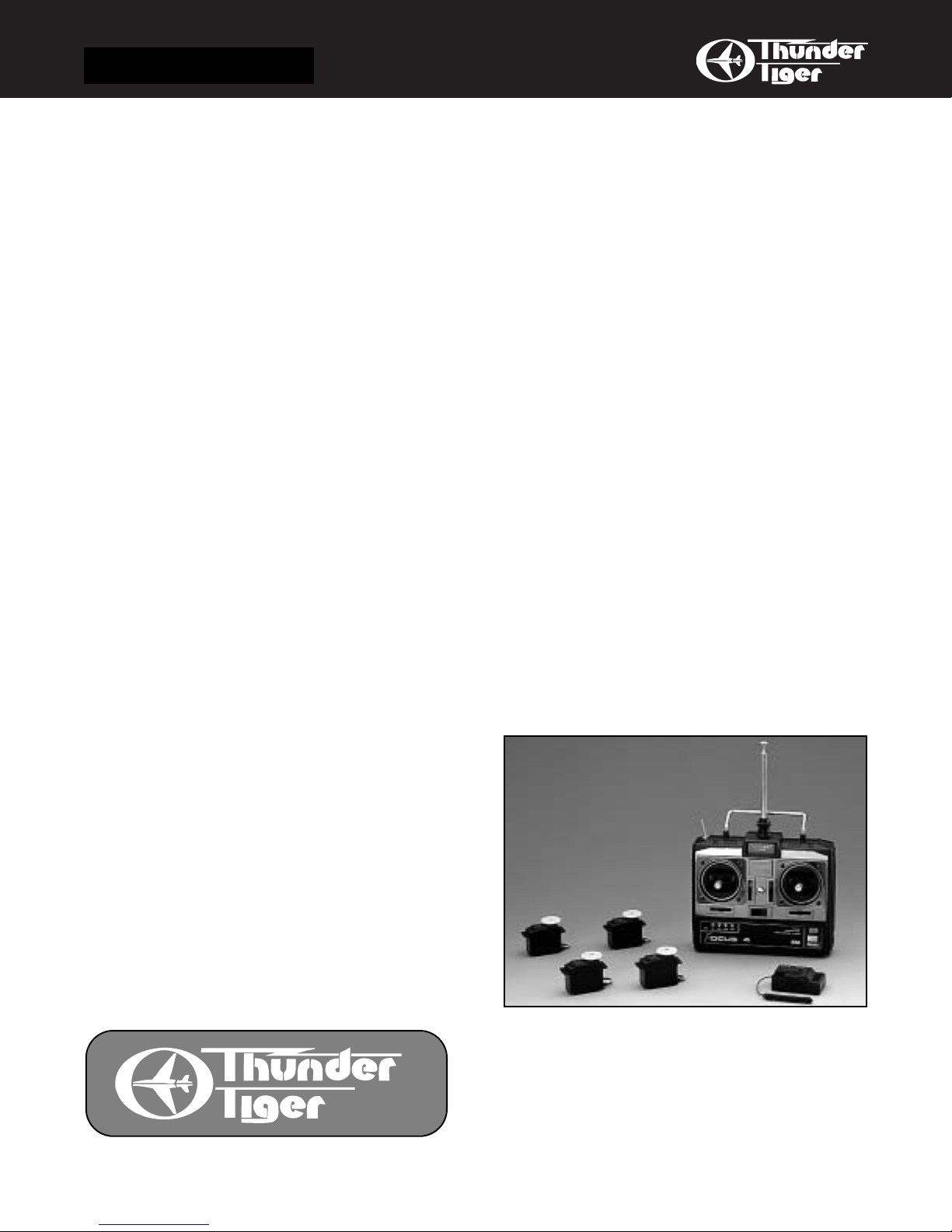
Radio - A 4-channel radio with four standard
servos is required.
Page 3
3
ITEMS NEEDED
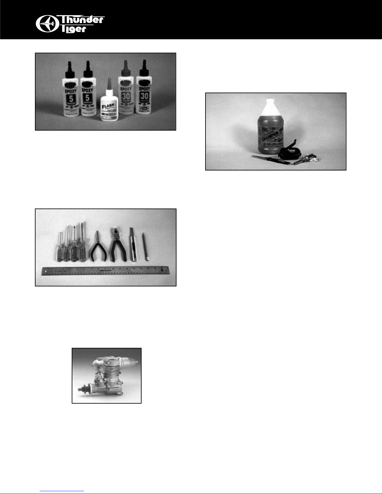
Adhesives - You will need two types of adhe-
sives for the Tiger Bipe - Epoxy and Instant
(cyanoacrylate) adhesives.We recommend that
you purchase both 5-minute and 30-minute
epoxy to cut down on assembly time, but you
can get by with only 30-minute epoxy if time is
not important. You will also need a small bottle
of both “Thick” and “Thin” instant adhesive.
Tools - Model assembly can be much easier if
the proper tools are used. Therefore, we have
included in our checklist to the right, a complete
listing of all the tools we used to assemble
our prototype models. As you will notice, many
household tools can be utilized during construction.
Engine - The Thunder Tiger PRO-36 is the ideal
engine for this airplane. It is a quiet running
engine that is easy to start and require no special break- in period, is very easy to maintain,
and will last for years.
Flight Equipment - There are several “support”
items that you will need to purchase in order to
get your engine running and your plane in the
air.These are listed at the bottom of the page.
Comprehensive Items Needed
Check List
❏ 4-Channel Radio with 4 Standard Servos
❏ 5-Minute Epoxy (4 ounces or so)
❏ 30-Minute Epoxy (4 ounces or so)
❏ “Thin” Instant Adhesive (1/2 ounce)
❏
“
Thick” Instant Adhesive (1/2 ounce)
❏ Hobby Knife and Blades
❏ Epoxy Mixing Sticks and/or Brushes
❏ Sandpaper (150 grit)
❏ Masking Tape
❏ Rubbing Alcohol
❏ Paper Towels
❏ Ruler
❏ 90 Degree Triangle
❏ Waxed Paper
❏ Fine-Point, Felt-Tip Pen
❏ Misc. Household Tools
❏ Drill and Bits (1/16", 5/64", 3/32", 5/32", 3/16")
Flight Equipment
❏ Foam Rubber Padding for the radio
❏ Stick on Lead Strip for balancing the plane
❏ 3 or 4 Props (see engine instructions)
❏ 10%-15% Glow Fuel
❏ Fuel Pump or Bulb
❏ Electric Starter or “Chicken Stick”
❏ Glow Plug Clip and Battery
❏ Extra Glow Plug(s)
Page 4
4
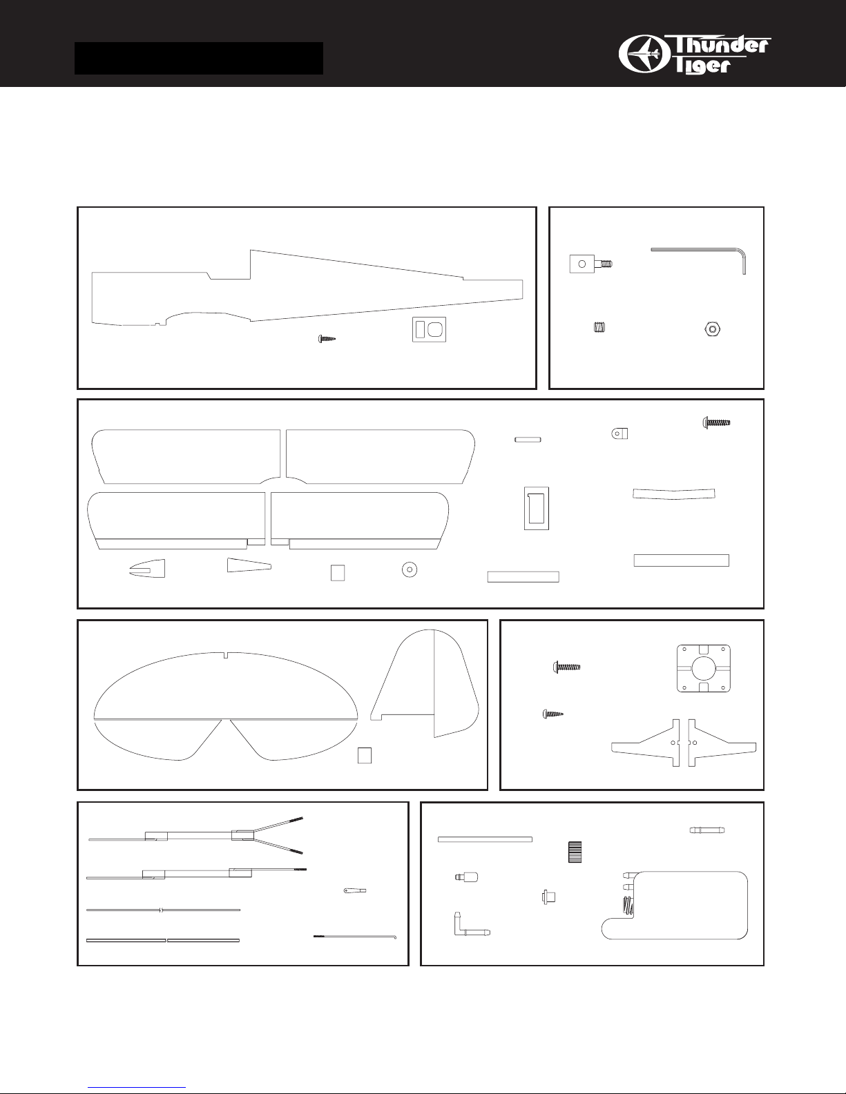
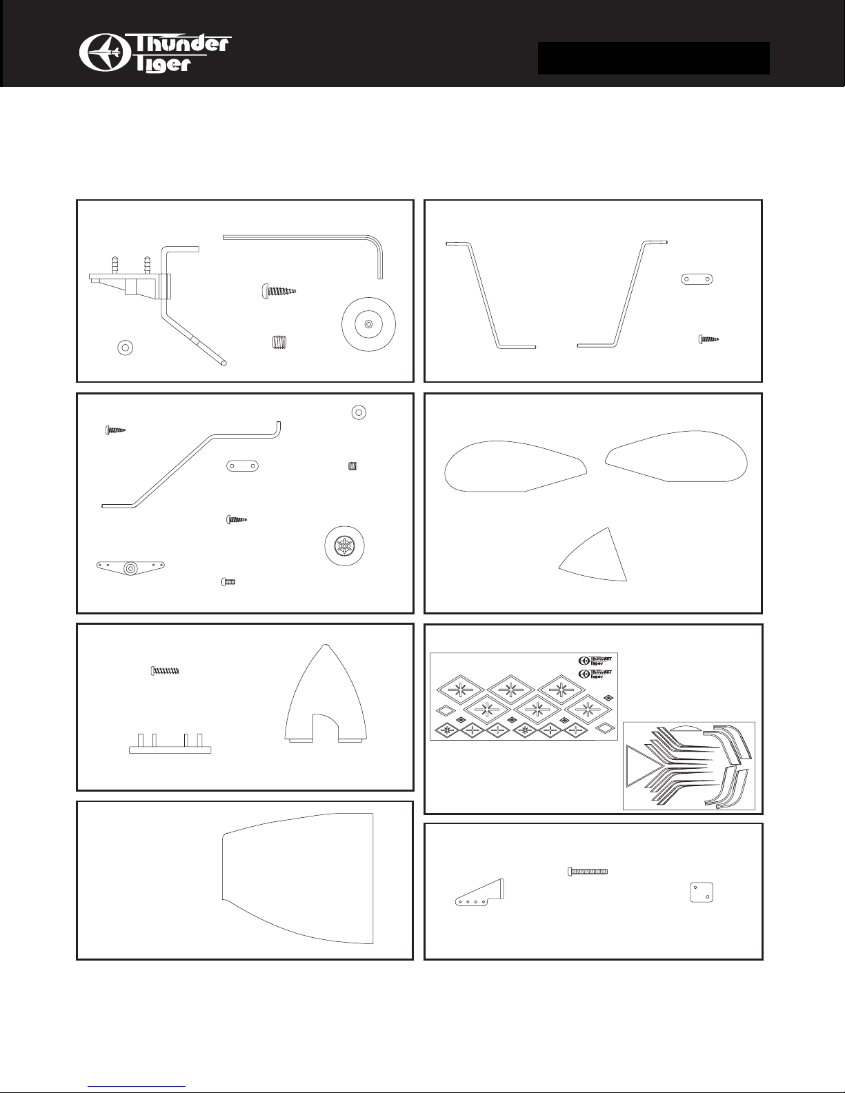
PARTS SKETCHES
IMPORTANT
Please check the contents of your kit box with these part sketches before beginning
construction.This will not only familiarize you with the parts and their names, but it will
also give you a head start in the unlikely event that you are missing a part.
Parts are not necessarily drawn actual size!
AS6119 Fuselage Set
Fuselage(1)
2x8mm Self-Tapping(4)
AS6120 Main Wing Set
Top Left Wing(1)
Bottom Left Wing(1)
Front Wing Dowel
Doubler(2)
Rear Wing Dowel
Doubler(2)
Top Right Wing(1)
Bottom Right Wing(1)
CA Hinge(6)
Washer(2)
Servo Tray(1)
Connector(1)
Wing Dowel(1)
Aileron Servo Tray(2)
Top Wing Joiner(2)
PE0009 Hardware Set
Allen Wrench(1)
Push Rod
3x3mmSet Screw(1)
Aileron Horn
Torgue(2)
Bottom Wing Joiner(2)
2mm Hex Nut(1)
Wing Bolt
6/32 x 24mm(2)
Trim Tape(2)
AS6121 Tail Feather
H. Stab./ Elevator(1)
AS6122 Pushrod Set
Stab Pushrod(1)
Rudder Pushrod(1)
0.05" Metal Pushrod(1)
Plastic Guide Tube(1)
V. Fin/ Rudder(1)
CA Hinge(8)
Clevis(5)
Aileron Pushrod(2)
3102 Adjustable Engine Mount
Screw 6/32 x 18mm(4)
Screw3x15mm(4)
3261 Fuel Tank Set
Silicone Tube(1)
Cap(1)
Clunk(1)
Rubber Stopper(1)
90-degree Nipple(1)
Engine Mount Plate(1)
Beams(L/1 R/1)
Straight Nipple(1)
180cc (6oz)
180cc Fuel Tank(1)
Page 5
5
PARTS SKETCHES
Parts are not necessarily drawn actual size!
Replacement parts must be ordered by Set Number
AS6007 Tail Gear Set
Allex Wrench (1)
Tail gear (1)
Collar (1)
3x10mm SelfTapping Screw(2)
3x3mm Set
Scrent(1)
AS6123 Main Landing Gear
3x12mm SelfTapping Screw(4)
Landing Gear(2)
Steering Horn(2)
Mounting Strap(2)
2.6 x 8mm SelfTapping Screw(4)
3x5mm Screw(4)
3x3mm Set Screw(2)
Wheel (2)
Tail Wheel (1)
4mm Collar(4)
AS6125 Cabane Strut
Mounting STRAP(4)
Cabane Strut(R/1) Cabane Strut(L/1)
2.6 x 8mm SelfTapping Screw(8)
AS6126 Wheel Pant / Canopy
Wheel Pant(R/2)
Canopy(1)
Wheel Pant(L/2)
3282R Spinner
3x12mm Self-Tapping Screw
Back plate(1)
AS6124 Cowl
Cowl(1)
AS6127 Decals
Tiger Bipe
THUNDERTIGER CORP.JE6352
2" Spinner(1)
AS6049 Control Horn Set
2x12mm Screw(6)
Control Horn(3)
THUNDERTIGER CORP. JE6353
Nut Plate(3)
Page 6
6
PRE-ASSEMBLY
❏ Note: the bottom wing is shorter than the top
wing and has ailerons. Before gluing the two
wing halves together, trial-fit the bottom wing
joiner into both wing panels. If it is not easy to
slide into the wing, sand it until it will. Note: this
joiner is the shorter of the two and has more
angle in it. To fit properly, note that the wing has
an upward “bend”in it, called dihedral. While fitting, also have the front and rear wing dowel
doublers temporarily in place.
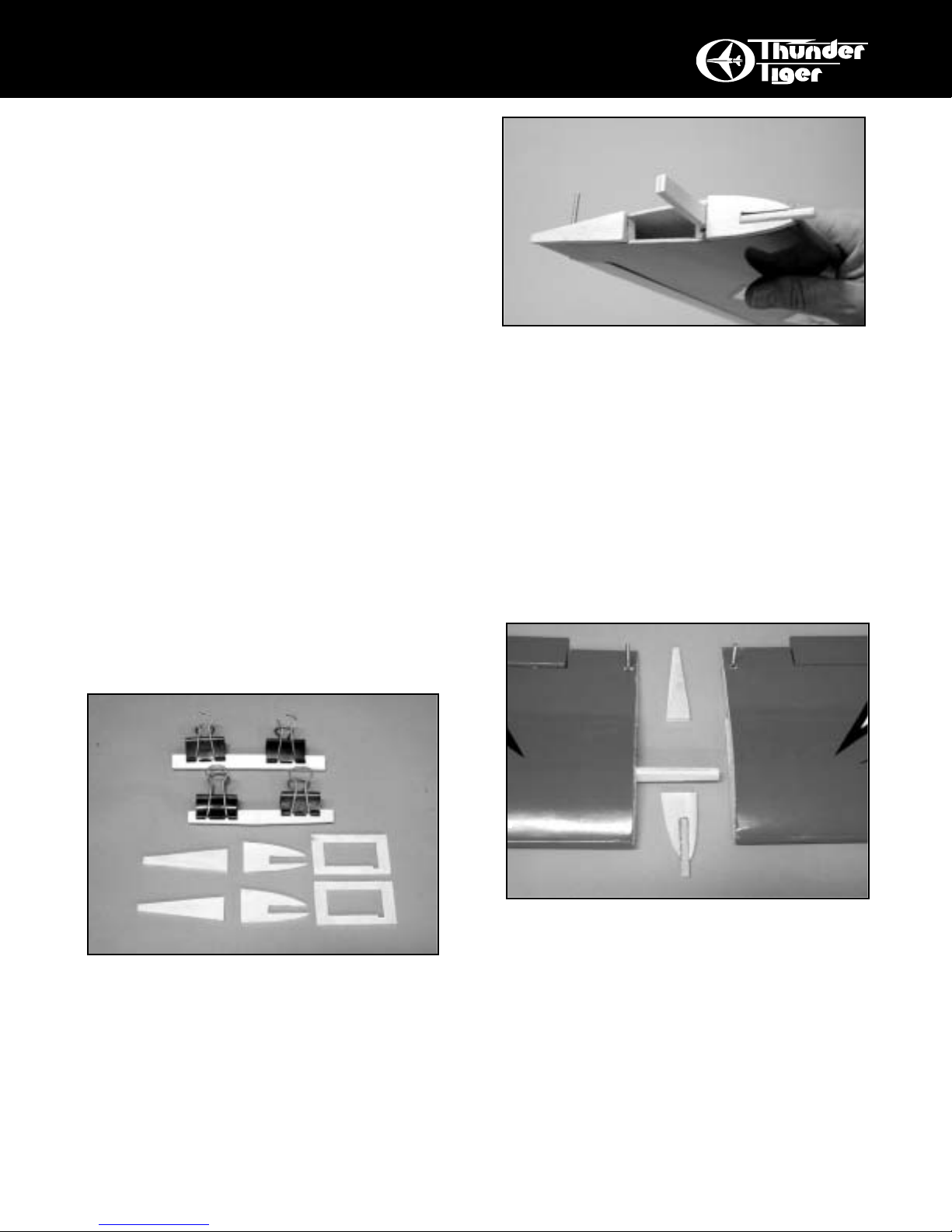
WING ASSEMBLY
❏ Locate the following pairs of plywood parts:
top and bottom wing joiners, front and rear wing
dowel doublers, and aileron servo tray. Using
epoxy or thick CyA, glue and clamp these pairs
of pieces together to form 6mm thick parts.
Keep the edges of the pieces lined up and wipe
off any excess glue.
PRE-ASSEMBLY NOTES
1. Please assemble your model according to
these instructions. Do not attempt to modify or
change in any way as doing so may adversely
change its flying characteristics.
2. Before you begin, please check the entire
contents of this kit against the parts list and
photo to make sure that no parts are missing or
damaged. This will also help you to become
familiar with each component of your plane. If
you find that any of the parts are either missing
or damaged, please contact your dealer immediately for replacement.
3. Each step of these instructions is preceded by
a box which can be check ed off as you complete
the step. This will allow you to follow your
progress and quickly find your starting place
after any interruptions or breaks.
Note: Your dealer cannot accept kits for
return if construction has begun
.
❏ With 30 minute epoxy, liberally coat all sides
and edges of the wing joiner and slip it into one
wing half. Now coat the inside edge of the center
wing rib where it will join to the other wing half.
This is called the “root” of the wing.
Put the front and rear wing dowel doublers in
place WITH THE WING DOWEL PLACED IN
ITS SLOT.
Now coat the root edge of the other wing
panel with epoxy.
Page 7
7
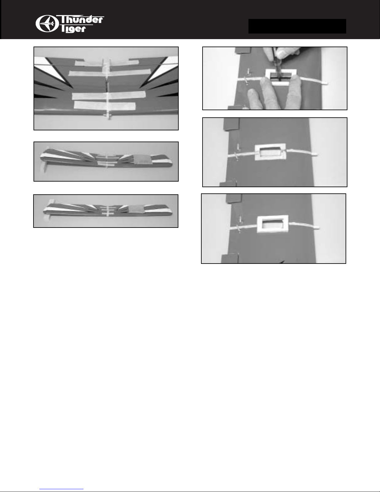
WING ASSEMBLY
❏ Join the two wing halves and firmly press
wing panels together. Wipe off any excess
epoxy with a paper towel and rubbing alcohol.
Make sure the two panels are accurately
aligned with each other and hold together with
several strips of masking tape.
To make sure you have the correct amount
of dihedral, place the wing on a flat surface;
keep one wing half flat on the surface and prop
up the other panel so there is 2” under the rear
part of the tip rib. Loosen the tape if necessary.
❏ Repeat for the top wing with two differences...there are no wing dowel doublers and
the total amount of dihedral is 3/4”.
❏ Place the servo tray in the middle of the top
surface of the bottom wing. Line it up with the
rear INNER edge aligned on the rear dowel
doubler. Mark around the inside and outside of
the servo tray with a felt tip pen.
❏ Remove the tray, and use a sharp knife to cut
through and remove the covering material and
balsa where you marked the INSIDE of the
servo tray.
❏ Use a sharp knife to score the cov ering material where marked around the OUTSIDE of the
tray. Remove the covering material to expose
the wood underneath. Use thick CA or epoxy to
glue the servo tray securely in place.
❏ Strips of covering film are provided to trim out
the center joint. You will need to use a covering
iron or a household iron to secure the film.
Page 8

8
WING ASSEMBLY
❏ To hinge the ailerons, remove the clear tape
that hold the ailerons in place, if necessary. Pull
the aileron off the wing, revealing the hinges.
Center these hinges in their slots in the
AILERON and secure them with THIN
CA,
letting it wick into the joint. Glue both surfaces
of the hinge.
❏ When the glue has set, re-install the aileron
onto the wing. Hint: if you trim a little bit off
each corner of the hinges, they will insert in the
slots easier. While flexing the aileron one way
or the other and while holding the wing up on
it’s front edge, carefully wick CA into the slot
where the hinge goes into the wing. Do so on
both sides of the hinge. After the glue has set,
tug on the aileron at each hinge location to
make sure the hinges are securely glued in
place. Also, make sure the aileron is free to
move up and down.
Repeat for the other aileron.
Set your wings aside, for now.
❏ Locate the tailwheel assembly. Obser ve that
is secured to the bottom of the fuselage with two
barbed posts. Mark the locations for these
posts on the rear of the fuselage so that the tiller
arm of the tail wheel assembly will be flush with
the rear edge of the fuselage. Drill 1/8” holes at
these locations and push the tailwheel assembly’s barbed posts into these holes. Your
assemble should be secure. If you want, you
can add some screws in the holes provided in
the assembly (not furnished.) The tailwheel is
secured with a wheel collar and set screw.
❏ Cut away the covering material that covers
the slot for the main gear. Insert the vertical
arm of one mail gear strut in the hole provided.
Repeat for the other. Secure them in place with
two landing gear straps and 3x10mm screws.
(Drill 3/32” pilot holes first.)
The wheels and wheel pants will be added
later.
Now that the plane is “up on its feet”, it will
be easier to work on.
INSTALL LANDING GEAR
Page 9
9
TAIL GROUP
INSTALL TAIL GROUP
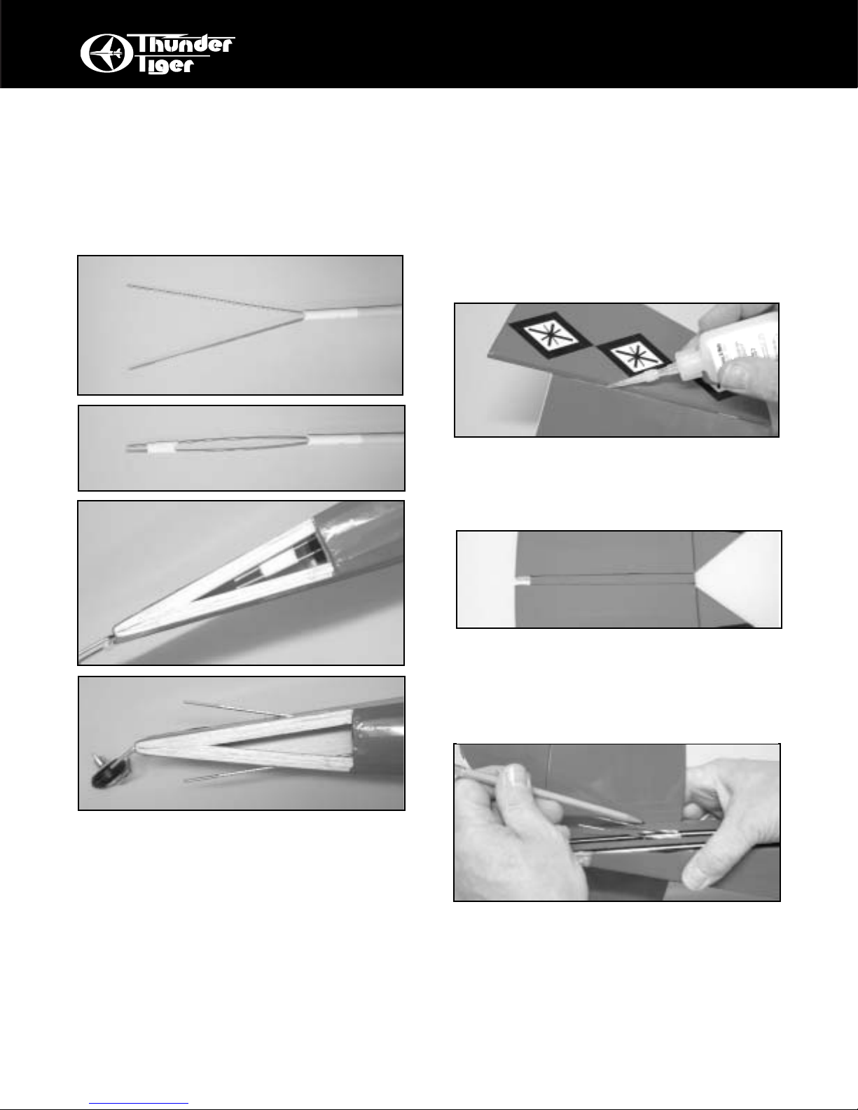
INSTALL PUSHRODS
❏ CA the hinges into the rudder and stabilizer
control surfaces using the same technique outlined for the ailerons.
❏ Trim the material away that covers a notch in
the front of the stabilizer. On the top of the
stab, use a straightedge and a pencil to extend
the lines formed by the notch back to the rear
of the stab. This mar ks the center of the stab.
❏ Position the stablilizer on top of the fuselage
and line up the mark you just drew on top of the
stab with the center of the fuselage; the rear
edge of the fuselage should line up with the
hinge line. Use a pencil to draw a line on the
bottom of the stab along the fuselage sides.
❏ Locate the elev ator pushrod. It is the one with
the two rods on one end.
Use a pliers and spread the two rods apart
so they are about 2” apar t at the end.
❏ Now, use some tape to hold the two rods
together so they are only about 1/2” apar t.
❏ Insert this pushrod into the fuselage. Note: It
is easiest to start at the opening in the tail, working from the tail end forward until the nonthreaded end is in the radio compartment.
❏ Cut the tape loose so the rods can spread
and let them come out the two uppermost slots
in the fuse sides.
❏ In the same fashion, insert the rudder
pushrod so the threaded end comes out the
lower slot in the right side of the fuse.
❏ Cut away the covering material over the two
uppermost slots that are on the right and left
sides of the fuselage at the rear.
Cut away the covering from the lowermost
slot on the RIGHT side of the fuselage.
Page 10

10
TAIL GROUP
❏ Move the rudder/fin into position
and mark the location of the tail wheel
assembly’s tiller
arm. Drill a 1/16”
hole in the rudder to
accommodate the
arm. Making sure the tiller arm slips into the
hole you just drilled, epoxy the fin to the stabilizer. Make sure the fin remains perpendicular
to the stab as the glue cures.
❏ Score and remove the covering material
between the lines you drew on the top of the
stab.The vertical fin will glue here.
❏ Next, apply a second, liberal coat of
epoxy to the joint
where the fin joins the
stabilizer. Form a filet
with the tip of your finger dipped in alcohol.
❏ Repeat this
process for the stabilizer/fuselage joint.
❏ Glue the stab to the fuselage with epoxy,
keeping the stab parallel with the work surface
as the glue cures.
❏ Remove the stab from the fuselage and use
a straight edge to carefully score the covering
material where marked.Make the score approximately 1/16" inside the lines you drew.It is very
important that you do not press hard enough to
cut into the wood itself or the stabilizer may fail
in flight. Just score the covering and it will peel
away nicely.
90°
Epoxy Filet
Page 11

11
ENGINE
❏ Attach the engine mount plate and both
mounting beams to the firewall using the 6-32 x
18mm screws provided.Make sure the mounting beam “webs” are on the outside of the
mount. Do not fully tighten the four engine
mount screws at this time.
❏ With the engine in place, mark the spot on
the firewall that is straight behind the throttle
arm on the carburetor and adjacent to the
engine mount back plate. This marks the hole
for the throttle linkage tubing.
Drill a 1/8” hole in the firewall at this mark.
Insert the furnished yellow “inner nyrod”into this
hole. It will act as a housing for the .050” music
wire throttle linkage.
❏ Remove the engine and drill a 3/32" hole at
each of the four marks you just made. “Breakin” the mounting holes by inser ting a 3 x 15mm
sheet metal screw into each hole without the
engine in place. A drop of oil in each hole may
help the screws thread in easier.
❏ Set the engine on the mount and adjust the
beams so they are almost touching both sides
of the engine crankcase and are centered in
relation to the engine mount back plate. Now
position the engine so that the front of the thrust
washer is approximately 4-1/4" from the fire
wall. Mark the hole locations for the engine
mounting screws in the engine mount beams.
INST ALL THE ENGINE
❏ Locate the music wire throttle linkage and
hook the “z” bend onto your engine’s throttle
arm and move the engine into position. You may
have to bend some jogs in the wire to prevent
binding of the linkage. Screw the engine in
place on the mount.
Page 12

12
FUEL T ANK
❏ Slide the fuel tank (cap end first) into the
front of the fuselage, threading the fuel lines
through the oblong hole in the firewall.The tubing coming from the tank’s fuel outlet (center)
goes to the carb and the tubing from the vent
(upper) goes to the muffler’s pressure fitting.
Trim the length as needed. Wedge some
pieces of foam rubber or “b ubb le wrap”(not furnished) beside and on top of the tank to gently
hold it in place.
❏ Attach a 6” piece of standard fuel line (not
furnished) to both the fuel outlet nipple and the
vent nipple on the tank. The vent nipple is the
top one with the hole.
❏ Assemble the fuel tank by first cutting the silicone tube to 2-1/2" in length. Press the straight
plastic nipple (the 90 degree nipple is not used
in this plane) into the rubber stopper (Saliva will
ease insertion.) Now slip the silicone tubing
onto the nipple and insert the metal clunk into
the other end of the tubing. Inser t this assembly
into the tank (clunk first) and securely tighten
the threaded cap on to hold everything together .
INST ALL THE FUEL T ANK
CABANE STRUTS
❏ Locate the holes in the side of the fuselage
for the cabane struts and cut away the covering
material that covers them.
❏ Insert the two preformed Cabane Struts in the
holes as shown. As you look at them, they
should form the letter “N”. You may have to run
a 1/8” drill bit in the holes to ease insertion.
Page 13

13
RADIO INSTALLATION
RADIO INSTALLATION
❏ Locate the three control horns and 2x12mm
screws. Also locate three of the nylon clevises.
Thread a clevis onto the rudder control rod until
about 1/8” of threads are showing on the inside
of the clevis body. Snap it onto the outer hole in
one of the control horns. Position the horn on
the rudder so the holes line up with the hinge
line. (For smooth operation, you may have to
bend the pushrod so it runs parallel to the fuselage.) Mark and drill 3/32” holes for the mounting screws and secure the horn with two screws
and the nylon nut plate.
❏ Repeat for the two elevator pushrods.
❏ Mount two ser vos on the servo tray which is
already installed in your fuselage. These are
for elev ator and rudder . Note their orientation in
the photo. Follow your radio’s instruction manual and make sure you use the grommets, eyelets, and screws furnished with your radio. Drill
1/16" pilot holes for the mounting screws before
insertion.
❏ Hook the pushrods to the servo arms marking the proper length and making “Z” bends in
the wire ends. A Z-Bend Pliers is a handy tool
for this purpose. Note that the rods hook on the
outside of the servo. This is to allow room for
the aileron linkage when the wing is installed.
❏ Mount the throttle ser vo tray into place with
four 2x8mm self-tapping screws in the fuselage
so the cutout for servo corresponds with your
throttle linkage. Mount the ser vo in place and
hook the throttle pushrod to the servo arm with
the "EZ Connect" furnished. Secure the body of
the EZ Connect to the arm with the small nut
furnished. Use the set-screw furnished to lock
the throttle pushrod wire in place. Trim the nylon
tube and wire as needed.
Page 14

14
RADIO
❏ Mount the aileron servo in the bottom wing as
shown. Screw the nylon horns fur nished onto
the threaded ends of the aileron torque rods;
screw down until about 1/16” of threads are
exposed above the horn. Use the threaded
rods, clevises, and “Z” bends to link the servo to
the ailerons.
Adjust the linkage so the bottom surface of
the wing is consistent with the bottom surface of
the ailerons when the servo is in neutral.
❏ When all is complete, install the receiver,
switch harness, and battery pack. The receiver
can go in the cutout in the throttle servo tray and
a flat battery pack will fit under the fuel tank.
You may need to reposition the battery to
achieve proper balance.
❏ Trim the rear of the cowl to remove the molding flange. Make cutouts as needed to clear the
prop shaft, cylinder head, carb, and muffler. A
sanding wheel on a Dremel tool is handy for
this.
With the cowl in position, drill 1/16” holes for
the small mounting screws in four places.
Locate them in the white area on the fuselage
side.
After the cowl is mounted, add the sticky
backed trim material to dress up your cowl.
Mounting Strap
3x12 Self Tapping Screw
2.6x8 Self Tapping Screw
Landing Gear Installation
Collar
Steering Horn
3x3mm Set Screw
3x5mm Screw
Page 15

15
COWL AND WHEEL PANTS
❏ Assemble and mount the wheel pants
according to the drawing.
Add the trim material furnished to dress up
the pants.
❏ Trim the excess plastic from the clear windshield and glue it in place with RC-56 canopy
glue or thick CA.
❏ The bottom wing is secured by means of two
6-32 bolts. The blind nuts are already installed
in the hold-down plate in the fuselage. Run the
bolts into the blind nuts so the head is about
1/2” from the hold-down plate.
Put the bottom wing in position with the
dowel going into the hole in the fuselage former .
Keeping the wing perpendicular to the fuselage,
press the wing into the bolts you just installed so
you leave an impression in the wood.
Remove the wing and, using the impres-
sions you just made, drill two 3/16” holes in the
wing for the bolts.
WING ATTACHMENT
Page 16

16
WING ATTACHMENT
BALANCE and SURFACE THROWS
❏ Set-up your radio so the airplane has the following throws. Make sure the directions of the
surfaces corresponds with the commands from
the transmitter; i.e., right is right and up is up.
Rudder = 3/4” Right and Left
Elevator = 1/2”Up and Down
Ailerons = 5/16” Up and Down
(Throws are measured at the rearmost edge of
the surface.)
Balance Point = 1/4”Behind Top Wing Main Spar
❏ To attach the top wing, begin by removing the
covering material over four slots in the bottom
surface of the top wing.
Put the top wing upside down on your work
surface using a piece of foam or a towel to protect the wing.
Place the cabane struts into position so the
wire is engaged in the slots you revealed earlier. The wing is held in place with four metal
straps and small self-tap screws. Position the
straps close to the bend in the struts. Pre-drill
for the screws with a 1/16” drill.
IMPORTANT- Do not attempt to fly your model
before completing this very important section.
A model that is not properly balanced will be
unstable and could cause serious damage
and/or injury.
❏ The balance point for this model is 1/4”
behind the main spar of the top wing, fully
assembled but without fuel.
Once you have everything positioned as
necessary, wrap your receiver and battery pack
in 1/4" or 1/2" thick foam for protection.
❏ Using the switch cover as a template, cut an
opening in the side of the fuselage to mount the
switch in. It should be on the left side of the
fuselage. Drill two 1/16" holes for the switch
mounting screws and install the switch. Drill a
1/16" hole through the fuselage side, about one
inch behind the switch mount. From the inside
out, thread the receiver antenna through this
hole.You may want to tie a knot in the antenna
3" or 4" from the receiver to act as a strain relief .
Attach the end of the antenna to the top of the
vertical fin with a small #10 rubber band and a
T-pin. Maintain only a slight amount of tension
on the antenna wire.
Page 17

17
FLIGHT
LOCATE A GOOD FLYING SITE
Generally, the best place to fly your model is at
an AMA (Academy of Model Aeronautics) chartered club field.Your local hobby dealer can tell
you if there is such a club in your area or write
the AMA for information.It is also a good idea to
join this organization before flying your model
since they offer liability insurance that can protect you if your model causes damage or injury
to others.
Academy of Model Aeronautics
5151 East Memorial Dr.
Muncie, IN 47302-9252
If there is not a chartered club field in your community, you will need to find a large area free of
obstructions, that has a smooth grass or asphalt
surface to be used as a runway. For safety’s
sake, it should be located well away from houses, building, schools, po wer lines and airports.If
you will be flying within 6 mile of an airport, you
should check with the airport manager before
flying your model.
ANOTEONBATTERIES
The batteries are the heart of your radio system. Make sure you have fully charged batteries! With rechargeable batteries, f ollo w the manufacturers instructions to make sure the batteries are fully charged, especially the first time the
radio is used.
If your radio uses dry cells, make sure your
batteries are in new condition.You have a lot of
money invested in this project so it is not wor th
the risk of using old batteries.
FLYING YOUR TIGER BIPE
You will find your Tiger Bipe ver y enjoyable
to fly. It is quite aerobatic and capable of very
“snappy” manuevers.
You will find this tail-dragger has great
ground handling and only requires a touch of
right rudder when you power-up. Let the airplane’s tail come up and fly it off the ground,
don’t horse it off with up elevator. The most
appealing aspect of flying this airplane is the
visual impact of a biplane. It puts you back to a
“Waldo Pepper” time when airplanes had to fly
on the wings, not on the prop. Fly your Tiger
Bipe the same way. Keep the maneuvers large
and smooth. When you are ready to tighten up
the maneuvers, gradually add some weight to
the tail to bring the CG rearward.
Landings are a breeze. Just adjust the altitude of the plane with the throttle, and the attitude with the elevator. Nothing is nicer than a
biplane making a perfect three-point landing.
PRE-FLIGHT CHECKS
You should perform these checks before each
flying session.
❏ 1. Check all control surfaces for possible
looseness or deterioration.
❏ 2. Check all screws, clevises, nuts and all
other connectors to make sure they are
securely fastened.
❏ 3. Check which radio frequencies are being
used. Do not turn on your radio until
absolutely sure you are the only one
operating on that frequency.
❏ 4. Check for proper operation of all control
surfaces.
❏ 5. Check the level of charge in both the
transmitter and receiver batteries before
flying.
❏ 6. Range check the radio both with and with-
out the engine running! Follow the radio
manufacturers instructions for this.
Page 18

18
POST-FLIGHT CHECK LIST
❏ 1. Be sure that both the transmitter and
receiver switches are turned off.
❏ 2. Drain all excess fuel from the tank. Fuel
left in the tank for extended periods can
“gunk up” the tank, fittings and carburetor.
❏ 3. Clean the plane with paper towels and a
light-duty spray cleanser. Keeping your
plane clean will make it last longer and
keep it looking nice.
❏ 4. Put a few drops of after-run or light oil in
the carburetor and turn the prop over a
few times (without the glow plug ignited)
to distribute the oil throughout the engine.
❏ 5. Inspect the prop and replace it if any
chips or cracks are found.
❏ 6. Inspect the entire plane for covering tears,
new dings and dents, loose screws and
connectors and any other wear and tear.
❏ 7. Use a voltmeter to check the receiver bat-
tery voltage. If it is low, you now know not
to fly so long next time.If it is still high, you
should be able to fly a little longer next
session.
SAFETY PRECAUTIONS
1. Wear safety glasses when starting and running all model engines.
2. Model engine fuel is very flammable and the
flame is very dangerous because it is almost
invisible! Do not smoke or allow sparks, high
heat or other flames near the fuel.
3. Do not r un model engines inside a garage or
other closed room as they give off large
amounts of deadly carbon monoxide gas.
4. Do not run model engines around gravel,
sand or other loose debris. These materials
will be ingested through the carburetor and
can also be kicked up by the prop.
5. Always stay behind the propeller when the
engine is running. Make all engine adjustments from behind the engine. Under no
circumstances should you allow your face or
body near the plane on rotation of the
propeller when the engine is running.
6. Do not allow loose clothing or other loose
objects close to the prop.
7. To stop an engine, cut off the fuel or air
supply to the engine. Do not throw rags or
other objects into the prop to stop the engine.
8. Do not touch the engine or muffler during or
right after it has been running–It gets very
hot!
9. If you hear any unusual noises while your
plane is flying, land at once and determine
the problem before returning to the air.
Control surface flutter, which often emits a
low-pitched “buzz”, can quickly destroy an
airplane and should not be ignored. Flutter is
usually caused by sloppy control surfaces
and is generally relatively easy to cure.
SAFETY
 Loading...