

Page 1
WARRANTY
Thunder Tiger Model Company guarantees this model kit to be free from defects in both material and
workmanship at date of manufacture. This warranty does not cover any components damaged by use
or modification and in no case shall Thunder T iger’s liability exceed the original purchase price of the kit.
Thunder Tiger also reserves the right to change or modify this warranty without notice.
Since Thunder T iger Model Co. has no control over possible shipping damages, construction techniques
or materials used for construction by the modeler, no liability can be assumed nor accepted for damage
resulting from the use by the user of the final user-assembled product. By the act of using this userassembled product, the user accepts all resulting liability. If the buyer is not prepared to accept this liability, he should return this kit in new and unused condition to the place of purchase for a full refund.
Assembly Instructions
&
No. 4517
No. 4518
Page 2
2
INTRODUCTION
INTRODUCTION
All of us at Thunder Tiger want to thank you for choosing the best-looking, lightest-weight,
and best -flying ARF available in this category of R/C, the profile fuselage Fun Fly. This kit features
state-of-the-art engineering that provides quick and easy assembly of a strong, yet lightweight airplane
that will provide you with an enjoyable experience. The Fun Tiger will do every maneuver in the book!
To gain the most from this airplane kit, it is important that you read the instructions thoroughly and
then follow them exactly. This instruction manual has been written with an inexperienced modeler in
mind, but includes many hints and modeling tips that even experienced modelers can benefit from.
We strongly suggest that you read through the instructions completely before beginning construction.
This will give you a good idea of the construction sequence and eliminate many questions you might
have if you did not read the manual prior to starting the actual construction.
The first thing you should do before beginning assembly is to check the contents of your kit against
the parts list on pages 4 and 5. If any parts are missing, contact your dealer immediately for
replacement. Customers in the United States and Canada may contact Ace Hobby Distributors direct-
ly at 116 W. 19th Street, Higginsville, MO 64037 660-584-6704 for replacement parts.
Under no cir-
cumstances can a kit be returned if assembly has already been started.
Introduction . . . . . . . . . . . . . . . . . . . . . . .2
Other Items Required . . . . . . . . . . . . . . .2
Items Needed Check List . . . . . . . . . . . .3
Parts Sketches . . . . . . . . . . . . . . . . . . .4-5
Pre-Assembly Fuselage . . . . . . . . . . . . .6
Pre-Assembly Wing . . . . . . . . . . . . . . .7-8
Pre-Assembly Hinging . . . . . . . . . . . . . . .8
Landing Gear . . . . . . . . . . . . . . . . . . . . .9
Install the Engine . . . . . . . . . . . . . . . . . .9
Install the Fuel Tank . . . . . . . . . . . . . . . . .9
Install the Linkage
. . . . . . . . . . . . . . . . . . . . . . .
10-12
Set-Up . . . . . . . . . . . . . . . . . . . . . . . . .13
Flying Hints . . . . . . . . . . . . . . . . . . . . . .13
Balance . . . . . . . . . . . . . . . . . . . . . . . .13
Pre-Flight Checks . . . . . . . . . . . . . . . . .14
Safety Precautions . . . . . . . . . . . . . . . .14
Post-Flight Check List . . . . . . . . . . . . .14-15
A checklist is also provided on the next page
which willmake shopping for these items easier.
TABLE OF CONTENTS
OTHER ITEMS REQUIRED
FOR ASSEMBLY
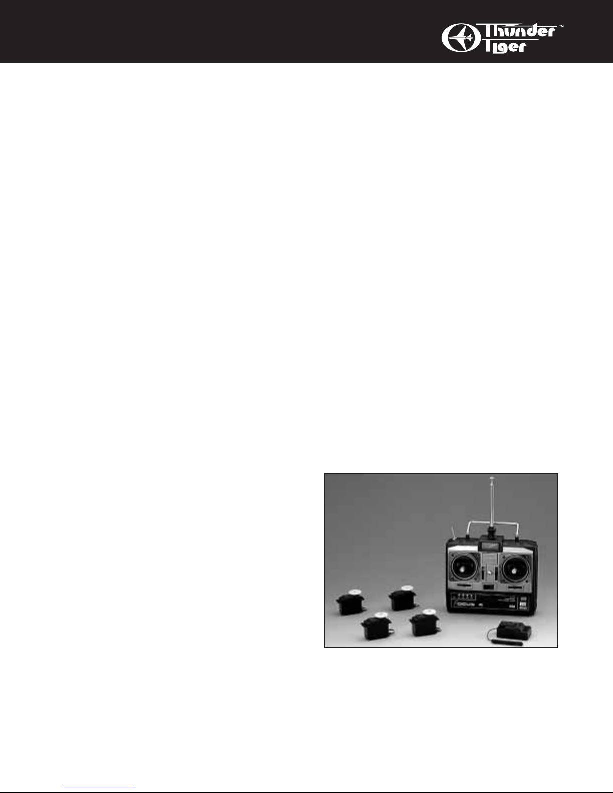
Radio - A 4-channel radio with five standard
servos is required. To achieve the maximum
maneuverability from this plane, we recommend
you use a computer-based radio for
elevator/flapperon mixing.
Page 3
3
ITEMS NEEDED
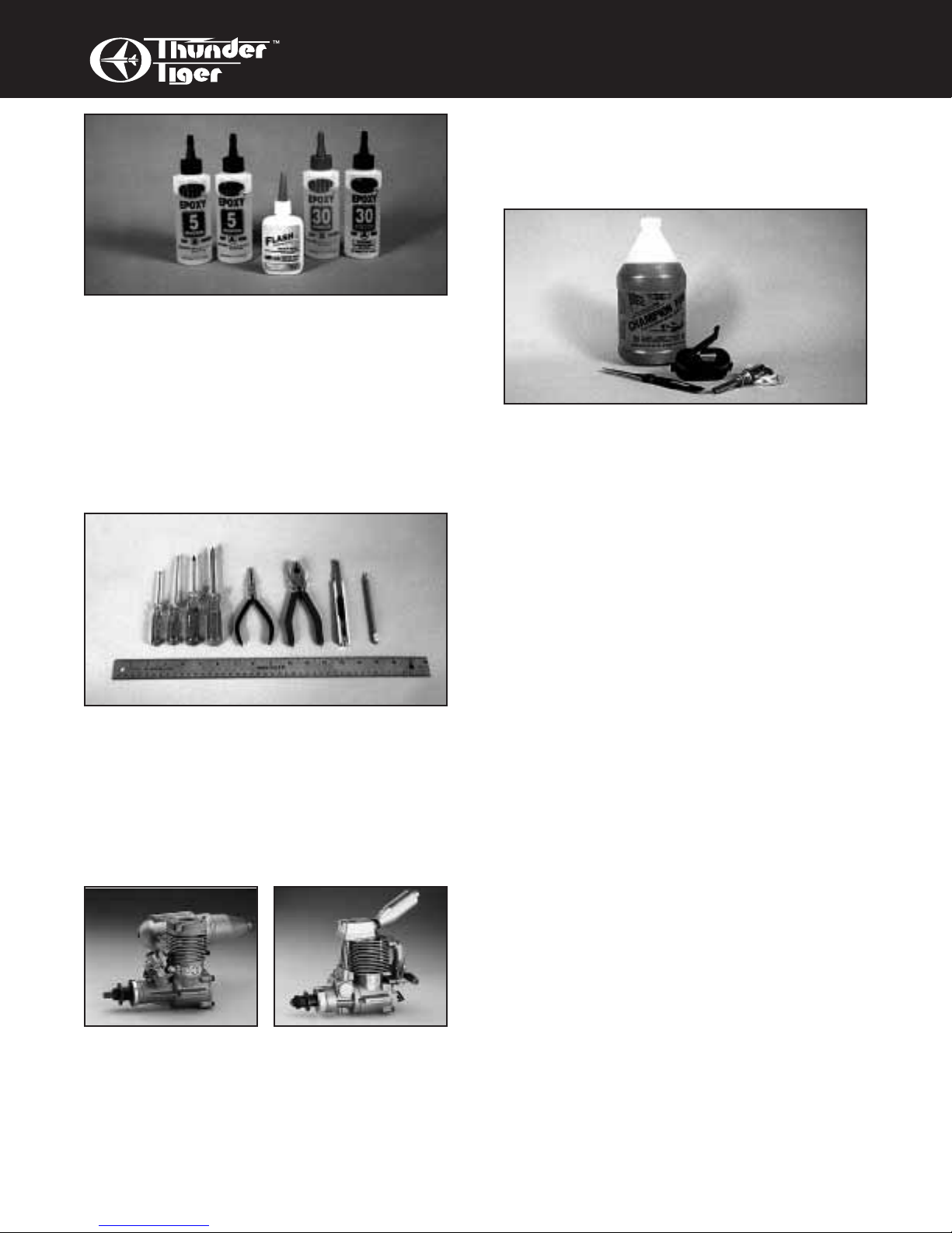
Adhesives - You will need two types of adhe-
sives for the Fun Tiger - Epoxy and Instant
(cyanoacrylate) adhesives. We recommend that
you purchase both 5-minute and 30-minute
epoxy to cut down on assembly time, but you
can get by with only 30-minute epoxy if time is
not important. You will also need a small bottle
of both “Thick” and “Thin” instant adhesive.
Tools - Model assembly can be much easier if
the proper tools are used. Therefore, we have
included in our checklist to the right, a complete
listing of all the tools we used to assemble our
prototype models. As you will notice, many household tools can be utilized during construction.
Engine - The Thunder Tiger GP-42, PRO-40/46
and F-54S are the ideal engines for this airplane. These quiet-running engines are easy to
start, require no special break-in periods, are
very easy to maintain and will last for years.
Flight Equipment - There are several “support”
items that you will need to purchase in order to
get your engine running and your plane in the
air. These are listed at the bottom of the page.
Comprehensive Items Needed
Check List
❏ 40 Size Engine
❏ 4-Channel Radio with 5 Standard Servos
❏ 5-minute Epoxy (4 ounces)
❏ 30-minute Epoxy (4 ounces)
❏ “Thin” Instant Adhesive (1/2 ounce)
❏“Thick” Instant Adhesive (1/2 ounce)
❏ Hobby Knife and Blades
❏ Epoxy Mixing Sticks and/or Brushes
❏ Sandpaper (150 grit)
❏ Masking Tape
❏ Rubbing Alcohol
❏ Paper Towels
❏ Ruler
❏ 90 Degree Triangle
❏ Waxed Paper
❏ Fine-Point, Felt-Tip Pen
❏ Misc. Household Tools
❏ Drill and Bits (1/16", 5/64", 3/32", 5/32", 3/16")
Flight Equipment
❏ Foam Rubber Padding for the Radio
❏ Stick on Lead Strip for Balancing the Plane
❏ 3 or 4 Props (see engine instructions)
❏ 10%-15% Glow Fuel
❏ Fuel Pump or Bulb
❏ Electric Starter or “Chicken Stick”
❏ Glow Plug Clip and Battery
❏ Extra Glow Plug(s)
Page 4
4
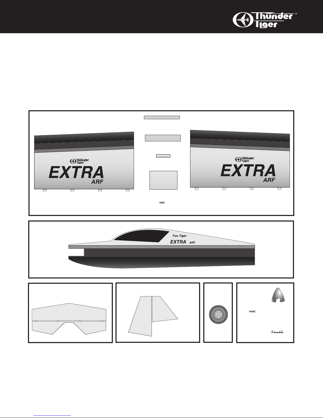
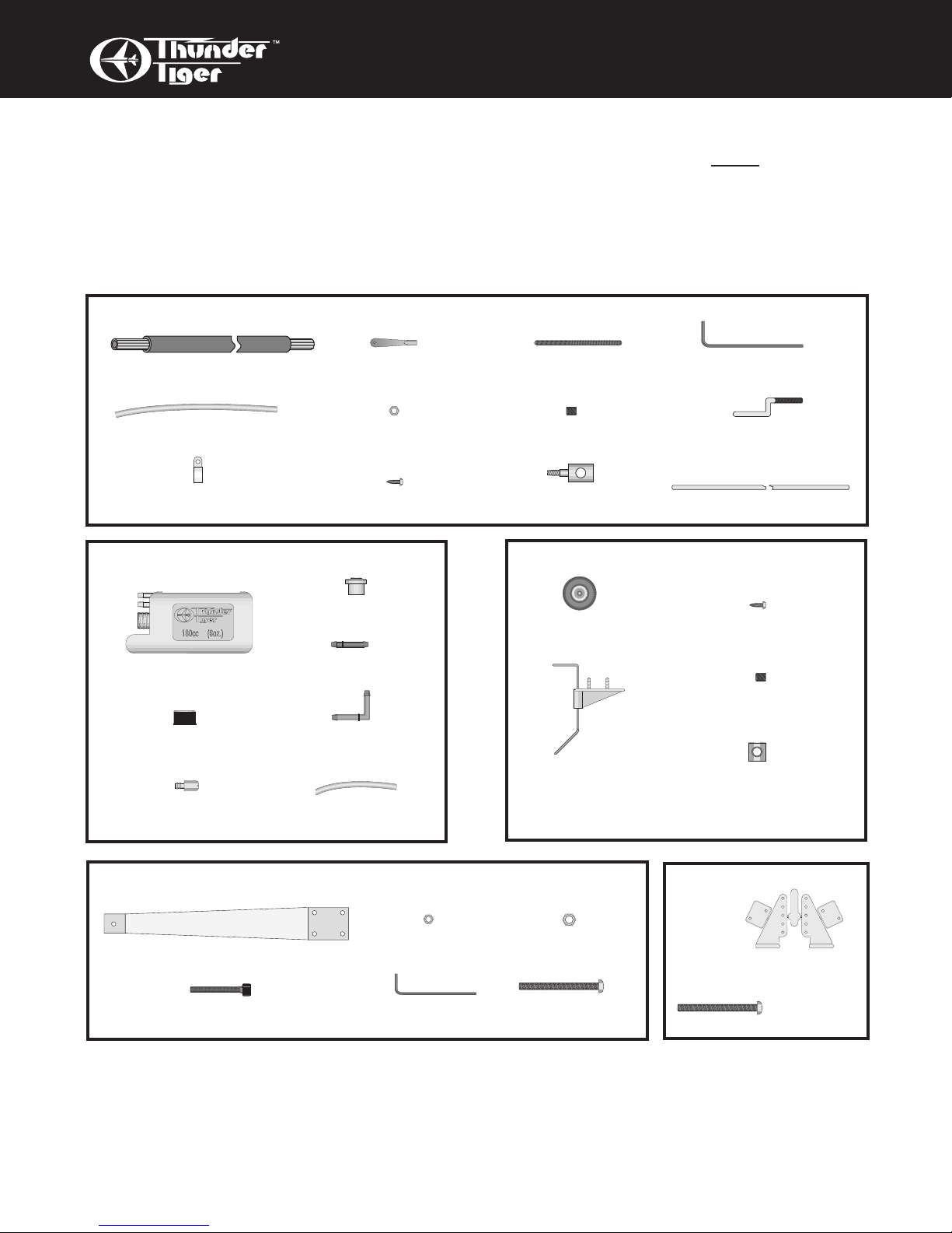
PARTS SKETCHES
IMPORTANT
Please check the contents of your kit box with these part sketches before beginning
construction. This will not only familiarize you with the parts and their names, but it will
also give you a head start in the unlikely event that you are missing a part.
If parts are missing, call (660) 584-6704.
Parts are not necessarily drawn actual size!
Left Wing (1)
Right Wing (1)
Spinner (1)
(2)
Tapping
Screw (2)
Backplate (1)
Wing Joiner (2)
Balsa Stick (2)
Balsa Hatch (2)
Dowel (1)
Wood Screw (4)
WING SET #AS6009
(#AS6002)
FUSELAGE #AS6008
(#AS6001)
HORIZONTAL TAIL #AS6011
(#AS6004)
VERTICAL TAIL #AS6010
(#AS6003)
WHEEL
#3256
SPINNER
#3284W
Page 5
LINKAGE BAG #AS6006
5
PARTS SKETCHES
Parts are not necessarily drawn actual size!
Replacement parts can be ordered by Set Number Only.
Individual parts not available.
Screw (8)
Landing Gear (2)
Socket Screw (2)
Allen Wrench (1)
Horn &
Backplate (2 pr)
MAIN LANDING GEAR #AS6005
CONTROL HORN
#3151
Screw (2)
3mm Hex Nut (4) 4mm Hex Nut (4)
FUEL TANK #3261
TAIL WHEEL SET #AS6007
Inner/Outer Nyrod (2)
Plastic Guide Tube (1)
180cc Tank (1)
Cap (1)
Clunk (1)
Fuel Stopper (1)
Silicone Tube (1)
Straight Nipple (1)
90˚ Nipple (1)
Pushrod Clamp (4)
Clevis (4)
2mm Nut (1)
Set Screw (1)
Set Screw (1)
Wheel Collar (1)
Tail Gear (1)
Piano Wire (1)
Z-Bent
Threaded End (2)
“EZ” Connect (1)
Threaded Stud (2) Allen Wrench (1)
Wood Screw (4)
Wood Screw (2)
Tail Wheel (1)
Page 6
6
PRE-ASSEMBLY
INTRODUCTION
1. The Fun Tigers are designed for the experienced R/C pilot. If you do not yet have the skills
to fly this outrageously maneuverable machine,
set it aside until you have progressed through
the trainer and intermediate stages of R/C flight;
you will then be ready for this plane.
2. Please assemble your model according to
these instructions. Do not attempt to modify or
change in any way as doing so may adversely
change its flying characteristics.
3. Before you begin, please check the entire
contents of this kit against the parts list and
drawings to make sure that no parts are missing
or damaged. This will also help you to become
familiar with each component of your plane. If
you find that any of the parts are either missing
or damaged, please contact your dealer immediately for replacement.
Note: Your dealer cannot accept kits for
return if construction has begun.
Note: Each step of these instructions is preceded by a box which can be checked off as you
complete the step. This will allow you to follow
your progress and quickly find your starting
place after any interruptions or breaks.
The following instruction manual
depicts the Fun Tiger Extra. If you are
building the Fun Tiger G-200, it builds
exactly the same; just disregard the differences in the color scheme.
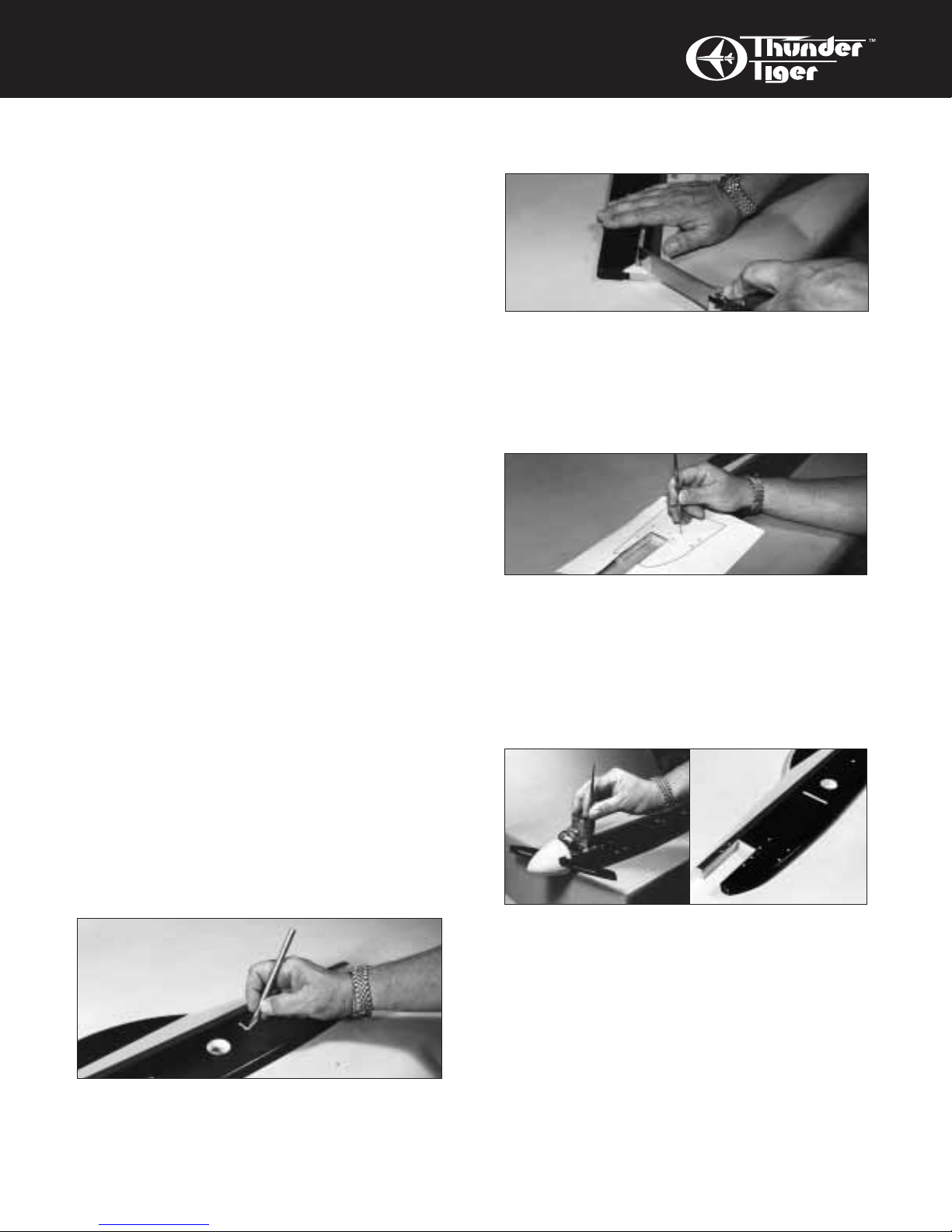
PRE-ASSEMBLY-Fuselage
1
❏ Using a sharp modeling knife, cut away the
covering film from both the wing joiner slot and
the 1/4”D alignment hole in the wing area on
both sides of the fuselage.
2
❏ Also cut away the film at the rear of the fuselage where the stab slot is. Notice that this
reveals the balsa tail post between the flaired
part of the stab slot. Use a razor saw or repeatedly cut with a hobby knife to remove the tail
post in this area.
3
❏ Locate the full size drill template. Cut away
the paper where indicated. Locate it on the left
side of the fuselage and tape in place. Using a
center punch or an awl, mark and drill four 5/32"
holes for mounting the landing gear then mark
and drill three 5/64" holes for the tank mounting
wires. Be careful to keep the drill perpendicular
to the fuselage.
4/5
❏ Position your engine in the cut-out area in the
front of the fuselage so the spinner will clear the
nose by about 1/8". Firmly holding the engine in
place, mark the four engine mounting hole locations. Drill four 5/32" holes where marked,
being careful to keep the drill perpendicular to
the fuselage.
Using medium CA glue or epoxy, coat the
exposed wood in the fuselage’s engine slot for
fuel proofing.
Page 7

7
WING ASSEMBLY
6
❏ Drill 3/16” holes in the bottom of the rear of
the fuselage to accommodate the barbed pins in
the tailwheel mounting bracket. Locate the
holes using the bracket/tailwheel assembly as a
guide. Line up the bracket so the “tiller arm”
portion of the wire is flush with the rear edge of
the fuselage.
PRE-ASSEMBLY-Wing
7
❏ Using epoxy, laminate the two plywood wing
joiners together. Clamp together keeping the
edges aligned; wipe off excess glue before it
sets. Allow to cure. When dry, sand all edges
of the joiner, removing any bumps or irregularities. Test fit the joiner into the slots of both wing
halves and trim as necessary for a good fit.
8/9
❏ Observe that there is an open bay in the top
of each wing. This is where the radio will go. To
gain access to this area, you will need to cut
away the covering film.
Begin by cutting the film diagonally across
the bay with a sharp modeling knife from corner
to corner.
Fold the material down into the wing and
press it down so it sticks to the vertical edge of
the wing sheeting. Note there is a 3/16" wide
ledge on both sides of the opening; press the
material down to this ledge and use your fingernail to burnish the material into the corners of
the ledge. Trim away the excess material.
Permanently stick the covering material to the
edges with a heat sealing iron set on low temperature.
10
❏ Locate the two 3-1/8" X 4-5/8" balsa hatches
and the two 1/4" X 4-3/8" balsa hatch tongues.
Using thin CA, glue a hatch tongue along the
long edge of one of the hatches leaving 1/8"
overlapping the edge and centering it lengthwise. Repeat for the other hatch.
11/12
❏ Put one of the hatches into place in the open
bay of one of the wing panels...the hatch tongue
is to fit into the rear edge of the opening; you
may have to do a bit of trimming on the tongue
for it to fit. With the hatch in position, drill a
1/16" pilot hole through both the hatch and the
plywood mounting platform about 1/2" from the
side and 1/8" back from the front edge of the
hatch. Remove the hatch and expand both
holes to 1/8". Now the hatch can be secured
with two self-tap screws furnished. Repeat for
the other hatch.
13
❏ Locate the paper template for cutting the
pushrod/nyrod slots. Trim along the lines that
indicate the center and the rear of the wing. Put
the template on top of the left wing panel and
line up the edges...tape the template in place.
Using a sharp modeling knife, cut two slots in
the wing sheeting in the location indicated;
make a few shallow cuts instead of one cut
Page 8

8
WING ASSEMBLY
all the way through. These are where the
pushrod and Nyrod will exit the wing when the
radio is installed. Repeat for the right wing
panel by putting the template on the wing
upside down.
PRE-ASSEMBLY-Cutting away
covering material
❏ In the following steps, you will be cutting
away covering material in preparation for gluing.
You have to be careful here. When cutting way
the covering, you need to use a sharp modeling
knife and only score the film itself. DO NOT cut
into the wood below the covering. If you do, the
structure of the airplane will be compromised
and failure may occur. Use a felt-tip pen to mark
the cutting locations as instructed.
14/15
❏ Begin with the fuselage/wing joint. Slip the
wing joiner into the slot in the fuselage and the
1/4" alignment dowel into the hole at the rear of
the wing location. It helps insertion if you round
over the edges of both the joiner and the dowel.
Slide both wing halves onto the wing
joiner/dowel until they butt up to the fuselage
side. Mark the fuselage around the outer
perimeter of wing. Remove the wing and carefully score the covering about 1/8" on the
INSIDE of these marks and peel off the covering to reveal raw wood at the wing/fuselage
joint. DO NOT GLUE THE WING IN PLACE!
YET.
6
❏ Put the fin into place in the slot in the rear of
the top of the fuselage. Mark the fin on both
sides where it meets the top edge of the fuse.
Take the fin out and remove the covering material about 1/32" below your mark.
❏ Slip the stabilizer into its slot in the fuselage.
Using a ruler to center the stabilizer and a Tsquare to make sure it is perpendicular to the
fuselage, mark where the fuselage meets the
stabilizer on the top and bottom. Slide the stab
out and remove the covering material about
1/32” on the inside of your marks.
PRE-ASSEMBLY-Hinging
❏ In the following steps, you will be mounting
the control surfaces by gluing the hinges in
place. All of the slotting has been done for you,
so it requires very little work. Begin by test fitting the ailerons to the wing, the elevator to the
stabilizer and the rudder to the fin.
17
❏ To help prevent glue from restricting the
hinge action, put a small drop of oil on the
moveable part of each hinge, being careful not
to get any oil on the flat surfaces of the hinges.
Lay them on a paper towel to absorb the excess
oil.
18
❏ We prefer to use 30 minute epoxy and do all
the hinging at one time.
The easiest way to accomplish this task is
to evenly coat the top and bottom surfaces of
one half of a hinge and slip it into its slot in the
control surface; do the same for the other
hinges in the control surface. This lets the control surface itself be your holding fixture. Then
coat both sides of the exposed half of all the
hinges. Next, slide the control surface in place,
starting at one end or the other.
Keep paper towels and some rubbing alcohol handy to clean up epoxy fingerprints on the
covering material before it sets.
Page 9

Page 10

Page 11

Page 12

Page 13

9
LANDING GEAR/TANK/ ENGINE
❏ Using epoxy, glue the tailwheel assembly in
place. Secure the tailwheel in place with the
wheel collar and set screw furnished.
❏ Mount the engine in place with four M3 X
30mm bolts, nuts, and washers.
❏ Mount the tank in place with “U” and “L”
shaped music wire brackets furnished. They
are inserted from the right side of the fuselage
through the holes you drilled earlier and then
bent over with a needle nosed pliers to form a
hook for rubber bands which in turn, secure the
tank.
❏ Now that your Fun Tiger is “up on its feet”,
use a triangle to check and see if it sits perpendicular to the work surface; slightly bend the
landing gear as necessary. Now, as you install
the wing and tail, you can easily check alignment.
ASSEMBLY-Wing
❏ Once again, test fit the wing onto the fuselage with the wing joiner and the alignment
dowel in place. When satisfied, use 30-minute
epoxy to glue the wing in place, making sure
you generously butter both sides of the wing
joiner plus where the wing root surfaces meet
the fuselage sides. Use a paper towel dampened with alcohol to remove the excess epoxy.
Make sure the wing remains in complete
contact with the fuselage as the glue sets.
❏ Using epoxy, join the control surfaces to the
flight surfaces with the hinges: rudder/fin, stabilizer/elevator, right wing/right aileron, and left
wing/left aileron. Keep the gap between the surfaces at a minimum.
When the epoxy has set, remove any
excess and check for free movement of the surfaces. Give a firm tug to each surface to make
sure the hinges are securely glued in; remember, this is a wild airplane and much stress is
placed on the control surfaces.
ASSEMBLY
Tank/Landing Gear/Engine
❏ Assemble the fuel tank by first cutting the silicone tube to 2-1/2" in length. Press the straight
plastic nipple (the 90 degree nipple is not used
in this plane) into the rubber stopper until the
molded-in ring is against the stopper. Rubbing
alcohol applied to the nipple will make it slip
inside the stopper easier. Now slip the silicone
tubing onto the nipple and insert the metal clunk
into the other end of the tubing. Insert this
assembly into the tank (clunk first) and securely
tighten the threaded cap to hold everything
together.
❏ Bolt the right and left aluminum landing gear
onto the fuselage using four M3 X 30mm bolts
and nuts. Note that the straight edge of the
landing gear goes to the front of the fuselage.
❏ Mount the wheels using M4 X 30mm socket
head bolts as an axle and two nuts on either
side of the landing gear to secure it.
Page 14

10
LINKAGE
ASSEMBLY-Tail Group
❏ Test fit the Fin/Rudder assembly into place
on the fuselage. Mark and drill a 3/32" hole
into the leading edge of the rudder to accommodate the tiller arm portion of the tailwheel
assembly. Test fit again and (if necessary)
notch the leading edge of the rudder to accommodate the tailwheel wire.
❏ Epoxy the stabilizer and fin onto the fuselage,
making sure the stabilizer stays in alignment
with the fuselage and the fin stays perpendicular
to the stab. Also make sure the tailwheel
assembly tiller arm slips into the hole you just
drilled in the leading edge of the rudder.
SERVO INSTALLATION
❏ Study the radio installation drawing.
Note that three servos are installed in the right
wing: the outermost servo is one of the two
aileron servos, in the middle is the throttle servo
and the rudder servo is on the inside.
In the outboard position in the left wing is
the other aileron servo; the elevator servo is on
the inside. Receiver and battery are foam
wrapped in-between these two servos and the
switch and charge jack are mounted to the
hatch in such a way that they don’t interfere with
the internal components.
❏ Use self-tap screws and grommets to mount
the servos to the rails in the wing so the output
arm will be in line with the slots you have
already cut. The throttle linkage will be dealt
with soon. Simply install the throttle servo
halfway between the aileron and rudder servo.
LINKAGE INSTALLATION
Elevator/Rudder Linkage
Hookup to the rudder and elevator is done
with “nyrod” pushrods consisting of an inner and
outer nylon tube. Athreaded stud and clevis on
each end connect to both the servo arm and the
control horns.
❏ Take a piece of 120 grit sandpaper and
roughen up about 2" of the outside of one end
of each of the two outer nyrods. Slip this end
into the slot in the LEFT wing that you cut earlier.
Rudder
Servo
Aileron
Servo
Aileron
Servo
Throttle
Servo
Elevator
Servo
Rudder/Elevator Linkage
Throttle Linkage
Aileron Linkage
Z-Bent
Threaded
End
Clevis
Music Wire
Threaded
Rod
Nylon Tube
“EZ” Connect
w/Nut & Set
Screw
Inner/Outer Nyrod
Control
Horn
Control
Horn
Page 15

11
LINKAGE
❏ You will need to drill a 3/16" hole through
the balsa webbing on the inside of the wing
to allow the inner nyrod to reach the servo.
Use the servo itself and the outer nyrod you
just slipped into place to determine the location.
❏ Next, thread one of the studs furnished
into one of the inner nyrods for about 3/8".
Screw a clevis onto this stud for about 3/8".
From the inside of the wing out, slip the inner
rod into the outer rod and hook the clevis up
to the servo arm. NOTE: a small screwdriver inserted between the forks of the clevis and carefully rotated will spread the forks
for installation. Route the nyrod down the
fuselage to the tail. The other end of this
nyrod will link to the elevator via a control
horn.
Page 16

12
LINKAGE
❏ Locate the nylon control horns. Cut them
apart and remove any flashing. Put a control
horn in position on the elevator so the nyrod
lines up nicely and the holes in the control horn
line up with the hinge line. Make sure the horn
is located on solid wood. Drill 5/64" holes in the
elevator to accommodate the mounting screws
for the horn. (A drop of CyA glue will hold the
horn in position while drilling.) Mount the horn
in place with two 2mm X 12mm screws and the
nylon screw plate.
❏ Making sure the other end of the inner nyrod
is still hooked to the servo, cut the outer nyrod
to within about 1-1/2" of the elevator control
horn. Next, cut the inner nyrod to the proper
length to accommodate the threaded stud and
clevis so you get neutral elevator when you
snap the clevis onto the control horn. Make
sure you allow for threading the stud into both
the inner nyrod and the clevis for about 3/8".
After you cut the nyrod, go ahead and thread
the stud and clevis in place and hook the clevis
up to the control horn.
❏ Secure the outer nyrod to the sides of the
fuselage in two places using the furnished
clamps and screws. These two places are, one:
where the vertical support member exists inbetween the two large open bays in the fuselage and, two: where there is “meat” right below
the front of the elevator.
❏ Repeat this procedure for the rudder nyrod
linkage on the right side of the fuselage.
Aileron Linkage
Hookup to the aileron is done with two
threaded rods with clevises/control horns on
the control surface end and a “Z-Bend” on the
servo end.
❏ You will need to drill a 1/8" hole through the
balsa webbing on the inside of the wing to allow
the wire to reach the servo
❏ Slip one of the threaded rods for the aileron
linkage through the slot in the wing and thread
on a clevis. Mount a control horn on the aileron
surface in the same manner as you did for the
elevator and rudder, keeping it parallel with the
fuselage.
❏ Put a “Z” bend in the servo end at the proper location so you get neutral aileron when the
servo is in neutral. Cut away the excess wire
and install the servo arm on the servo with the
linkage in place.
❏ Repeat for the other aileron.
Throttle Linkage
Throttle linkage consists of a piece of music
wire inside a nylon tube with a “Z-Bend” on the
servo end and an “EZ Connector” on the carburetor arm.
❏ First, a 1/8" hole needs to be drilled through
the leading edge of the wing to accommodate
the nylon tubing. The easiest way to do this is
with a long drill bit from the outside of the wing
through the the radio compartment. “Eyeball”
the hole so the linkage will be a straight line
between the throttle arm on the engine and the
servo arm.
❏ Install the nylon tube in the hole you just
drilled and glue in place.
❏ Complete the linkage using the furnished
“EZ Connector” secured to the throttle arm with
nut furnished. Aset screw locks the music wire
where needed. A“Z” bend links the music wire
at the servo end.
Receiver/Battery/Switch
❏ The receiver and battery pack are located in
the area between the two servos in the left
wing. Use as much foam as you can in the
limited room available but make sure there is no
bind on the linkage.
❏ Mount the switch on the left hatch cover,
making sure it clears the internal components.
Page 17

Remove or add weight as needed to balance
the airplane at the root of the wing(near the
fuselage) as follows:
Initial Set-up: 4-1/4" back from leading edge
of the wing, measured at the fuselage.
Advanced Set-up: maximum of 4-3/4" back
from leading edge...work in 1/4" increments.
FUN FLYING HINTS
Take a close look at your Fun Tiger. Notice
it’s thick airfoil, large control surfaces, generous
vertical fuselage area, short coupled nose and
tail, and BIG engine. Now pick it up and feel
how light it is. All of these attributes contribute
to the flight characteristics of this airplane which
you are about to discover when you take your
new Fun Tiger to the flying field.
There is a very good reason this category of
airplanes is called “Fun Fly”; flown properly , they
can be an outrageous amount of fun because of
the outrageous things they will do. Following
are a few hints to maximize the Fun out of your
Fun Tiger.
FIRST and FOREMOST, this airplane is
not designed to fly fast. DO NOT fly this air-
plane straight and level at full throttle with a
PRO 46.! If you do, the control
surfaces may
flutter with loss of the airplane
. It is necessary to
continually change the throttle and only apply
full throttle when you are going straight up or at
other times when needed (loops, rolls, etc.),
then backing down to idle when you are going
straight down. The rest of the time, you will be
in the mid-range.
Due to the enormously large ailerons, you
will find the roll rate so fast it will startle you the
first time you give full aileron. Forget about
feeding in down while you’re in the inverted
position....there’s no time.
Loops are so tight, you’ll think the prop is
going to chew off the tail. This is especially true
if you couple elevator to flapperons with a computer radio. Follow the programming sequence
for your radio to set up flapperons then mix
elevator to flapperons 100% or 1:1.
13
SET-UP
SET-UP
Initially, set-up the throws for your control
surface as indicated in the following chart. They
are measured at the rearmost point of each control surface. Of course, make sure transmitter
command directions correspond with surface
movement; i.e., up is up and right is right!
Non-computer radios:
Lo Rate Hi Rate*
Aileron: 3/4" Up/Dn 1-1/2" Up/Dn
Elevator: 1" Up/Dn 2" Up/Dn
Rudder: 1-1/4" Rt/Lt 3" Rt/Lt
Computer radio notes: Engage flapperon mixing and mix flaps with elevator; we suggest 1 to
1 in opposite directions (up elevator/down flaps)
*Exponential is recommended instead of
dual rates....set max throw to these limits.
Center Of Gravity (Balance Point)
Low Throttle/Low Throttle Trim
Low Throttle/Mid Throttle Trim
High Throttle/Mid Throttle Trim
Set-up your throttle as
shown.
Page 18

14
PRE-FLIGHT/POST-FLIGHT
POST-FLIGHT CHECK LIST
❏ 1. Be sure that both the transmitter and
receiver switches are turned off.
❏ 2. Drain all excess fuel from the tank.
Fuel left in the tank for extended periods
can “gunk up” the tank, fittings and
carburetor.
❏ 3. Clean the plane with paper towels and a
light-duty spray cleanser. Keeping your
plane clean will make it last longer and
keep it looking nice.
❏ 4. Put a few drops of after-run or light oil in
the carburetor and turn the prop over a
few times (without the glow plug ignited)
to distribute the oil throughout the
engine.
❏ 5. Inspect the prop and replace it if any
chips or cracks are found.
❏ 6. Inspect the entire plane for covering
tears, new dings and dents, loose
screws and connectors and any other
wear and tear.
SAFETY PRECAUTIONS
1. Wear safety glasses when starting and
running all model engines.
2. Model engine fuel is very flammable and the
flame is very dangerous because it is
almost invisible! Do not smoke or allow
sparks, high heat or other flames near
the fuel.
3. Do not run model engines inside a garage
or other closed room as they give off large
amounts of deadly carbon monoxide gas.
4. Do not run model engines around gravel,
sand or other loose debris. These materials
will be ingested through the carburetor and
can also be kicked up by the prop.
Make sure the flaps go DOWN when you
give UP elevator! Put the mixing on a switch so
you can engage it when you want. Experiment
at altitude initially.
Snaps and spins are dramatically quick and
tight; knife edge flight and knife edge loops are
relatively easy; plus lightweight makes hovering
possible and acceleration instant.
Quick response is the main reason we
recommend exponential control on the flight
surfaces with a computer radio. With exponential,
you get full response at the extremes of control
stick movement, yet a softer feel for smooth
control around neutral. We suggest you set the
dual rate switches the same for both HI and LO
so they can’t be in the wrong position at the
wrong time. Set the throw limits as indicated in
“Set-Up” under the “Hi Rate” column and
program the exponential for 50% to begin with.
PRE-FLIGHT CHECK LIST
❏ 1. Check all control surfaces for possible
looseness or deterioration.
❏ 2. Check all screws, clevises, nuts and all
other connectors to make sure they are
securely fastened.
❏ 3. Check which radio frequencies are
being used. Do not turn on your radio
until absolutely sure you are the only
one operating on that frequency.
❏ 4. Check for proper operation of all control
surfaces.
❏ 5. Check the level of charge in both the
transmitter and receiver batteries before
flying.
❏ 6. Range check the radio both with and
without the engine running! Follow the
radio manufacturers instructions for this.
Page 19

THE PERFECT ENGINE FOR YOUR
FUN TIGER!
15
5. Always stay behind the propeller when the engine is running. Make all engine adjustments
from behind the engine. Under no circumstances should you allow your face or body near the
plane on rotation of the propeller when the engine is running.
6. Do not allow loose clothing or other loose objects close to the prop.
7. To stop an engine, cut off the fuel or air supply to the engine. Do not throw rags or other
objects into the prop to stop the engine.
8. Do not touch the engine or muffler during or right after it has been running–It gets very hot!
CHOOSE THESE FINE PRODUCTS FOR YOUR FIELD EQUIP-
TTR9141 Thunder Tiger PRO-46
The PRO-46 is the perfect engine for your Fun
Tiger, with plenty of power and a great sound.
TTR2702 Thunder Tiger Power Monitor
The perfect device to distribute the power of a 12V field
box battery: metered hi efficiency glow driver, fuel pump,
and starter.
TTR3302 Thunder Tiger Tiger Tote™
Keep all your stuff organized with a Tiger Tote, with a
pre-cut power panel slot and available with or without
Remote Starting System.
TTR1102 Thunder Tiger 4-Way Wrench
Thunder Tiger’s lightweight 4-way wrench fits all glow
plugs and prop nuts, plus has room to store extras.
TTR1658 Thunder Tiger Fuel Pump
Our most popular fuel pump; fuel and defuel from a 12V
source; fuel filter and fuel line included.
TTR2674-2675 Thunder Tiger Starters
Keep all those fingers on your hands with budget-priced
Thunder Tiger starters, available in two sizes, starting
engines from 1/2A to 1.20.
Copyright 1998 by Thunder Tiger Corporation, all rights reserved.
Thunder Tiger, Fun Tiger, Fun Tiger Extra, Fun Tiger G-200, Champion 45-S, Champion 45L, Tiger Stick, Regular Combo
Plus, Regular Combo+, Tiger Tote, their logos and likenesses thereof are trademarks of the Thunder Tiger Corporation.
Page 20

16
Tiger Stick RCP
TTR4509-A+
Thunder Tiger
PRO-46
Thunder Tiger
PRO-46
The “Regular combo Plus”(RCP) is a new concept in R/C. If you have some flying experience
under your belt and already have a couple of
radios, you may not want to buy another. Check
this out.
When you get a Regular Combo Plus, the
engine, servos, and switch harness is included and
all of the work is
done for you.
The engine is installed, the servos are
secured and hooked up to the control surfaces
and the switch harness is mounted. All you have
to do is plug in your existing receiver and battery
pack, join the wing halves, install the stab, bolt on
the landing gear and you are ready to fuel and fly!
Three of Thunder Tiger’s more advanced airplanes
are available in the Regular Combo Plus lineup.
Thunder Tiger
PRO-40
Champion 45L RCP
TTR4456-A+
Champion 45-S RCP
TTR4512-A+
FOR YOUR NEXT PROJECT:
 Loading...