

Page 1
JE6990/3
14
Assembly Manual
Floats
Many thanks for the purchase of the Floats. This set contains a pair of strong, lightweight floats
molded in special ABS plastic, together with all fittings required, water rudder and associated
linkage. The floats is designed specifically for Thunder Tiger Ready (No.4591) that you can
convert to a seaplane easily.
Please read the manual thoroughly and check the contents before you start the assembly. You
will need 2mm and 5mm drill bits during assembling. Regarding tools and glues, they are same
as you used for Ready .
Strongly recommend to install the PRO-46 on the Ready Float plane, as GP-42 might be not
powerful enough to take off.
Step vs C.G.
13. Bend the two ends of the Spring so it can hook to the
steering arm. Thread the other end of the wires to the
springs, same way to loop the brass tubes. Make sure
the water rudder works smoothly and same direction as
rudder. Adjust the wires for proper tension so both
rudder and water rudder are in neutral position then
clamp the tubes.
Introduction
Notice: Adult Super Vision Required
This is not a toy. Assembly and flying of this product requires adult supervision.
Read through this book completely and become familiar with the assembly and flight of this airplane.
Inspect all parts for completeness and damage. Browse www. thundertiger. com for customer service
if you encounter any problems.
Flying Tips
During the slow taxing phase it is essential to hold in full up-elevator to keep the nose up. Taxi as slowly as possible to
avoid spraying and splashing. Use the rudder (i.e. the water rudder) for course correction only; the ailerons should only
be used to hold the model straight in a side-wind. Take-off must always be directly into wind; start by opening the throttle
slowly with full up-elevator held in. As soon as the model rises onto the step , i.e. when it is gliding on the underside
of the floats, the elevator must be returned to neutral. Allow plenty of time, i.e. more than you generally use on land. The
drag of floats is much higher than of a wheeled undercarriage. Always land in plenty of time, i.e. well before you run out
of fuel, as you will need a longer motor run than you are used to when flying from land in order to taxi the model back to
the bank. For the landing fly into wind as usual and flare the model with a higher angle of attack than usual. The waves
can be uncomfortably high, and the model will tend to bounce unless you are very careful.
1.Refer to Ready safe cautions.
2.Nylon or fiberglass propeller is recommended.
Also check that there is sufficient clearance between the propeller tips and the top surface of the floats.
3.Only fly when engine is powerful and smoothly.
4.Do not fly on a flowing water like creeks or rivers.
5.Do not attempt to fly if there is any wildlife or people in the water.
6.Check the wind direction then choose a good location for flying. The wind can carry it back to the shore if engine is quit.
7.If plane is stuck out on the water, do not attempt to swing to get it back as it is very dangerous and difficult. A good way
to get your plane back, retrieve the stalled or capsized model plane with a fishing rod that equips a real. Tie a tennis
ball on at least 12 lb. string. Of course, retrieve the plane with a boat is the best.
Safety Tips
11.Thread wire through the angled brass tube on the float,
next thread the small holes to the servo compartment.
Warranty
Specifications:
Length: 33.46” (850mm)
Weight: 1.42lbs. (642g)
This kit is guaranteed to be free from defects in material and workmanship at the date of purchase.
It does not cover any damage caused by use or modification. The warranty does not extend
beyond the product itself and is limited only to the original cost of the kit. By the act of building
this user-assembled kit, the user accepts all resulting in liability for damage caused by the final
product. If the buyer is not prepared to accept this liability, it can be returned new and unused to
the place of purchase for a refund.
Floats
10mm(3/8”)
12.Remove the nose gear steering pushrod from the
servo horn, next change the Z-bend ends to the second
hole of the servo horn. Same way to make a loop and
circle to the servo horn at the outmost holes and clamp
the tubes as photos shown.
Double check the balance point of your Ready, it must be
80mm( 3 1/8 ) from the leading edge of the wing.
To obtain this position first try moving the receiver
battery and then if needed, add some lead. The step
should be about 10mm (3/8 )after the C.G. Position.
around - ”
”
Page 2

2 3
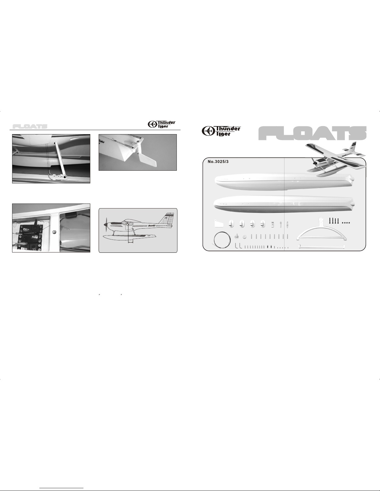
Kit Contents:
Floats
Description Q'ty
2
4
1
9
1
1
1
1
1
1
Floats
3. the Sand the glue area of the plug and hole on the
float, next epoxy the plugs in place. Note the plug
w/Rudder Bush will be at left float which you drill an
extra hole for the brass tube mount.
1.Locate two identical Floats, drill 5mm holes on the
molded dots for four nylon Mounting Brackets(Left/2,
Right/2) at least 30mm( 1-3/16 ).
Place the Brass Tube Mount as indicated position then
drill 3mm(1/8 ) hole through the mount and to the float.
Next enlarge the hole on float to 5mm(13/64 ) and drill
at same depth.
”
”
”
2.Trial fit the plastic sleeve and make sure the depth is
just flush with the sleeve, remove the sleeve and
roughen the plastic sleeves with sandpaper( 150 grit).
Glue all the sleeves in place with epoxy. Note that the
holes are faced up . Make sure there is no epoxy inside
the hole of the sleeve.
ASSEMBLY
4.Locate the Water Rudder, Rudder Shaft and Rivet.
Insert the rivet then use hammer to secure the rudder in
place. Note: The rivet has a hole on one end, suggest to
place a Phillips Screw Driver on the hole then slightly hit
the driver so the rivet will break evenly. Next hit the rivet
directly until water rudder is secured firmly but still can
swivel back .
5.Install the water rudder in the plug w/bush then secure
the Steering Arm in place with 2.6x8mm wood screw.
6.As floats are always in water, use care to apply the
decal or it will be pilled easily.
Clean the surface of the floats before applying the decals.
7. Remove nose gear then install the Nose Brace on the
firewall with the screws.
Float
Mounting Bracket (Left/2, Right/2)
Brass Tube Mount
Plastic Sleeve
Plug
Plug w/Rudder Bush
Steering Arm
Water Rudder
Rudder Shaft
2.9x13mm Rivet
1
2
9
1
1
2
4
1
2.8M Wire
Tension Spring
3x15mm Wood Screw
Cross Bar
Nose Brace
4x30mm Socket Head Screw
4mm Locknut
2.6x8mm Wood Screw
Description Q'ty
8.Secure all mounting brackets on the floats with
3x15mm wood screws. Next Secure the Nose Brace
and Main Landing Gear on the brackets. Use Socket
Head Screws 4x30mm for Nose Brace and 4x40mm for
Main Landing Gear also secure the cross bar to the Main
Landing Gear.
9.Drill two small holes around 2mm( 5/64 ) at the left
side of the fuselage as indicated in the illustration.
”
10. Locate the Angled Brass Tubes and mount, install
the tubes in the mount then secure the whole assembly
on the float with 3x15mm wood screw.
4
2
2x5mm Brass Tube
Angled Brass Tube
2
4x40mm Socket Head Screw
1
Sticker
Before assembling the float set we suggest to remove all the flash by using 200-grit sandpaper.
The float set is not necessary to paint. If you would like to paint the float and (or) other parts, this is the time
to do it. Any fuel-proof paint and do not damage ABS material may be used. Please be aware of the
dangers that the use of some paints brings, if any doubt contact your paint supplier.
Before Painting carefully sand every part using 400 grit sandpaper, then use a mixture of water and a few
drops of washing up liquid to remove any trace of dirt from the parts.
We do not recommend painting the bottom of the floats.
“”
 Loading...