

Page 1
Page 2

INTRODUCTION
2
IMPORTANT NOTES & WARNING
3
ITEMS REQUIRED FOR OPERATION
4
UNWRAPPING CONTENTS FROM BOX
5
CHARGING THE GLOW PLUG IGNITER
5
INSTALLING TIRES / WHEELS
5
PREPARING THE RADIO
6
RADIO BATTERY INSTALLATION
6
RADIO OPERATION
6
OPERATING RADIO STEERING FUNCTION
7
OPERATING RADIO THROTTLE/BRAKE FUNCTION
7
ADJUSTING THROTTLE/BRAKE LINKAGE
8
ADJUSTING CARBURETOR
8
FUELLING
9
PREPARING THE ENGINE FOR STARTING
9
STARTING THE ENGINE
10
ENGINE BREAK-IN & ENGINE SETTING
10
SHOCK AND REAR TOE-IN ADJUSTMENT
11
BODY CUTTING
11
2 SPEED ADJUSEMENT
11
TROUBLESHOOTING
12
Thank you for purchasing the Thunder Tiger ER-1 Nitro Powered 4WD All Road Car. Thunder Tiger
strives to bring you the highest level of quality and service we can provide. We race and test our
products around the world to bring you state-of-the-art items.
This user guide contains the steps you will use to prepare and use your new vehicle. Please read
all instructions and familiarize yourself with the systems and controls of this product before operating.
You should enjoy many hours of trouble free use from this advanced R/C product. We offer online help 24-7 on our www.acehobby.com forum and our product specialists are ready to take your
call if you have any technical questions. Have fun and enjoy the exciting world of R/C.
Thank you for purchasing a Thunder Tiger Product.
Please read all instructions and familiarize yourself with the products and controls before
operation.
1. This product is not a toy. It is a high performance model product. It is important to familiarize
yourself with the model, its manual, and its construction before assembly or operation. A child
operating under the supervision of the adults is necessary.
2. Always keep this instruction manual ready at your hand for your assembling and operating
reference, even after completing the assembly.
3. Make sure all the screws are properly tightened and all the parts are checked after running the
car for a long period of time.
4. For the best performance, it is important to make sure all the moveable parts work free without
binding.
5. Do not operate model products in rain, on public roads, near crowds, near airport, or near areas
with restricted radio operation.
6. Always keep fuel away from heat and open flame. Only operate in open, well-ventilated area.
Store fuel in cool, dry area. Keep the fuel bottle cap tightly closed. Clean up any leak or excess
fuel before starting the engine.
7. This product, its parts, and its construction tools can be harmful to your health. Always exercise
extreme caution when assembling and/or operating this product. Do not touch any part of the
model that rotates.
8. Check your radio frequency with the proper operating frequency of the area or country. Always
check to see if there are any modelers operating on the same frequency as yours. Also, check
your radio for proper operation before operating a model.
CAUTION
INDEX
INTRODUCTION
Page 3
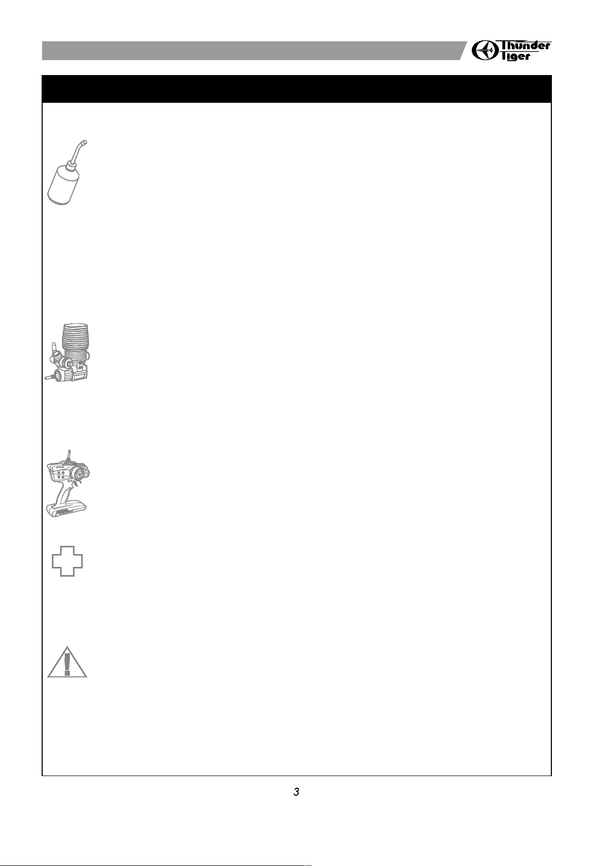
1. Choose a fuel from a reputable, brand name company that is approved for car/truck use.
Do not use airplane or boat fuels in your car/truck. Choose methanol based model engine
glow fuel that has a nitro content in the range 10%-30% and 5% to 18% caster/synthetic oil
content for lubrication. Lower nitro percentages will generally result in a cooler engine running
temperature and therefore last longer before needing a rebuild; cooler-running engines also
generally produce less power. 20% nitro is the most widely used fuel.
2. Fuel color is for identification purpose only and is not important to performance or durability
of your engine.
3. Be careful. If the tank overflows it might get on your radio gear or on your brakes and it may
create an unsafe driving situation. Always keep your fuel bottle closed when not in use.
4. Do not dispose of fuel or empty fuel containers in a fire. It may possibly cause fire or explosion.
1. For proper engine break-in procedure, please refer to the manual of your engine.
2. Never run your vehicle without the air filter .If the vehicle will be operated in an area with
fine dust, use filter oil or caster oil on the air filter element. It is important that the foam is
only moist to trap dirt and allow air passage. With the foam too wet, limited air can pass
through; therefore, limiting engine performance.
3. The parts around engine could be dangerously hot after operation. Do not touch it without
any protection!
1. When turning radio on, first turn on the transmitter and extend the transmitter antenna.
2. Then, turn on the receiver. When turning off, first turn the receiver off, then the transmitter
off.
1. If you drink nitro fuel by accident, immediately drink large quantities of water and try to induce
vomiting. Consult with physician right after then.
2. If the nitro fuel gets into your eyes, rinse them well with water. Consult with physician right
after then.
3. If the fuel gets onto your skin, wash it well with soap and water.
FUEL SELECTION
1. Improper operations may cause personal and/or property damage. Thunder Tiger and its
distributor have no control over damage resulting from shipping, improper construction, or
improper usage.
2. Thunder Tiger assumes and accepts no responsibility for personal and/or property damages
resulting from the use of improper building materials, equipment and operations. By the act
of assembling or operating this product, the user accepts all resulting liability. If the buyer is
not prepared to accept this liability, then he/she should return this kit in new, unassembled,
and unused condition to the place of purchase.
ENGINE
RADIO OPERATION
FIRST AID
WARNING
IMPORTANT NOTES & WARNING
Page 4
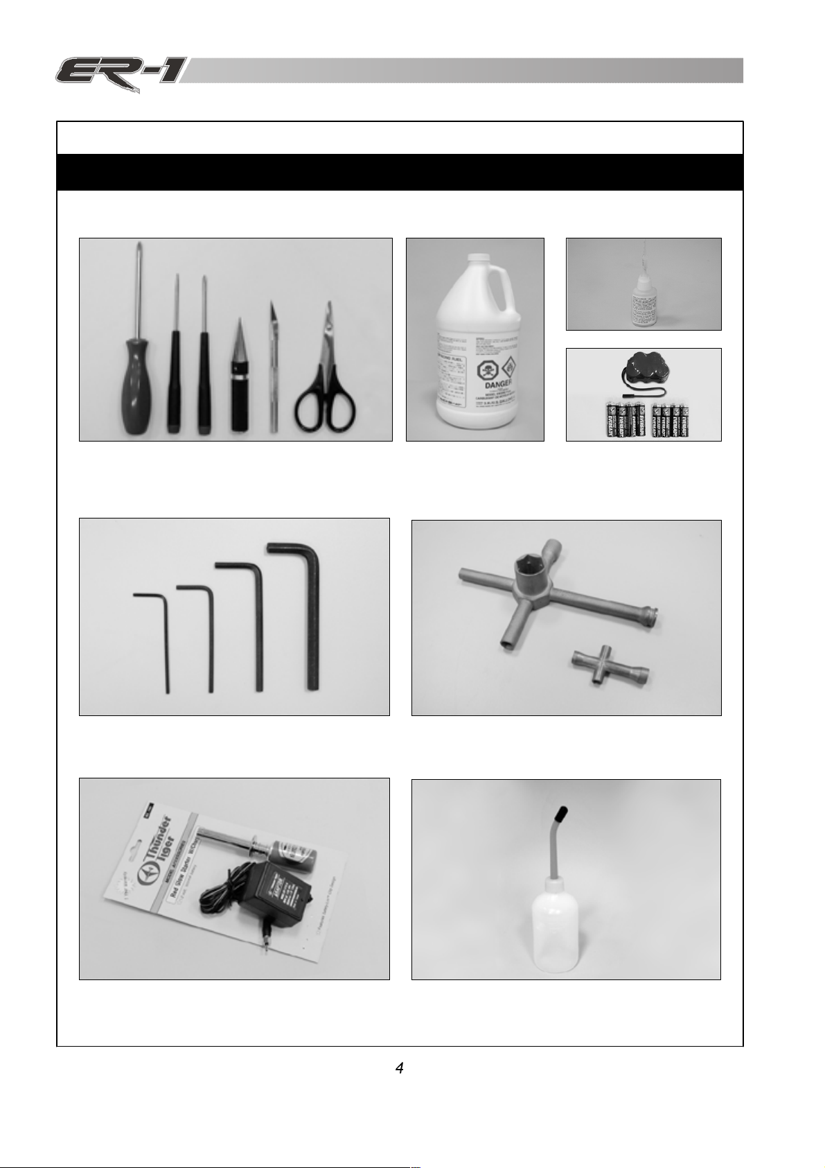
5-WAY WRENCH
ITEMS REQUIRED FOR OPERATION
Fuel Bottle
Glow Starter w/ Charger
Hex Wrench Set, 1.5mm / 2.0mm / 2.5mm / 5.0mm
4-Way, 5-Way Wrench
CA Glue / Instant Glue
Screw Drivers, Lexan Body Reamer, Hobby Knife,
Lexan Scissors.
Glow Fuel, Methanol
10% to 30% Nitro
5% to 18% Caster / Synthetic Oil
RX Battery pack and battery
charger
Page 5

a.
Plug the charger into an AC outlet, and then pull on the igniter lever to accept the charging adapter.
b.
At this point, the small red LED indicator on the charger should light up indicating the charging sequence
is in progress.
c.
When the charging complete, pull on the glow plug igniter lever to unplug the glow igniter.
Charge the new glow plug igniter for 16 to 24 hours on the first charge. For subsequent charges, charge
it about 12 hours before next use.
NOTE:
If the igniter gets warm or hot during the charge, unplug the igniter from charger immediately. A warm /
hot igniter means the igniter is overcharged. Overcharging can damage the internal battery in the igniter;
thus, shortening its life.
CHARGING THE GLOW PLUG IGNITER
a b c
1
a.
Contents of the box are secured with reusable zip-ties. To unlock zip-tie, press on the small lever.
b.
Pull on the zip-tie while keeping the small lever pressed. Pull the zip-tie out completely.
UNWRAPPING CONTENTS FROM BOX
a b
b
a
INSTALLING TIRES / WHEELS
a.
Insert the axle pin into the hole.
b.Apply the supplied lock nuts onto the wheel axle.
c.
Turn the wrench to tighten the wheel nuts
c
2
3
Page 6

b
a.
Install 8 AA-size alkaline batteries into transmitter.
b.
Connect the battery connectors from the switch with battery pack.
c.
Install the battery into the receiver box. secure the box with a long body clip.
RADIO BATTERY INSTALLATION
a
b
c
a.
Check the frequency printed on the transmitter crystal.
b.
Remove the radio receiver from box with a screw driver. Check the frequency printed on the receiver
crystal, and make sure it matches with the transmitter crystal. Make sure no one will operate on the
same frequency when you are. When there is a radio glitch, it will most likely be caused by improper
crystal, damaged crystal, or people operating on the same frequency. After checking, place the receiver
back in the box and secure the receiver box top.
c.
Install the antenna into transmitter.
PREPARING THE RADIO
a
c
5
4
a. When turning radio on, first turn on the transmitter.
b.
Then, turn on the receiver. When turning off, first turn the receiver off, then the transmitter off.
c.
To reverse the functions of servos, use the small, white servo reverse switches located on side of the
pistol transmitter (or the inset servo reverse switches located at the bottom of the stick transmitter). To
trim the servos on pistol transmitter, use the trim switches on side of the steering wheel (the ST. trims
steering, and the TH trims throttle/brake). On a stick transmitter, the trim levers are located accordingly
around the sticks.
d.
For more details, please check the transmitter instruction manual.
RADIO OPERATION
a b c
6
Page 7

a.
Check the radio steering functions. With the radio transmitter and receiver on, turn the steering wheel
/ stick to the left. The front tires/wheels should turn left accordingly. If not, flip the steering servo reverse
switch.
b.
Return the steering wheel / stick to neutral. The front tires/wheels should point straight forward. If not,
use the steering trim lever to correct it.
c.
Turn the steering wheel / stick to the right. The front tires/wheels should turn right accordingly.
a b c
OPERATING RADIO STEERING FUNCTION
a.
Check the radio throttle/brake functions. With the radio transmitter and receiver on, pull the trigger /
push the stick forward. The carburetor should be fully opened and the brake disengaged. To reverse
this function, flip the throttle/brake servo reverse switch.
b.
Return the trigger / stick to neutral. The carburetor should be closed to a point where the idle has
been set (see step 9 & 10 for settings), and the brake still disengaged. If not, use the throttle/brake
trim lever to correct it.
c.
Push the trigger / pull the stick backward. The carburetor opening should still be the same at neutral,
throttle spring compressed slightly, and the brake engaged.
a
b
c
OPERATING RADIO THROTTLE / BRAKE FUNCTION
8
7
Page 8

a b c
ADJUSTING CARBURETOR
a.
To set the high speed needle (large needle sticking out from the carburetor body), turn the screw as
pictured. Initial high speed needle setting should be 2.5 turns (close the needle completely, then back
out 2.5 turns). Clockwise turn will provide leaner setting (lower fuel to air mixture), and counterclockwise
turn will provide richer setting (higher fuel to air mixture).
b
.
To set the carburetor idle (small needle sticking out from the carburetor body), turn the screw as pictured.
Initial idle setting should leave 1mm carburetor gap. Clockwise turn will provide higher idle (larger
carburetor opening), and counterclockwise turn will provide lower idle (smaller carburetor opening). For
more details about the engine setting, please refer to ENGINE BREAK-IN/SETTING procedures to
properly set the engine.
c.
To set the low speed needle (The low-speed mixture screw is located in the end of the carburetor).
turn the screw as pictured. This screw controls how much fuel enters the engine at idle and low throttle.
This adjustment will smooth the idle and improve the acceleration to mid speed. Make this adjustment
with the throttle closed, after setting the idle. Turn the screw clockwise gently until it bottoms out. DO
NOT over tighten. Now turn the low-speed mixture screw counter-clock 6 1/2 turns.
d.
Remove the outer foam from filter and make it moist evenly with a few drops of fuel. Put the filter in a
plastic bag and knead it until the foam is saturated, but not soaked.
e.
Finally, make sure the air cleaner boot is securely fastened with a zip-tie.
Never run your vehicle without the air filter .If the vehicle will be operated in an area with fine dust, use
filter oil or caster oil instead of fuel. It is important that the foam is only moist to trap dirt and allow air passage.
With the foam too wet, limited air can pass through; therefore, limiting engine performance.
d e
d
a.
To set the throttle/ brake linkage, first the radio should be on and neutral; thus, the servo is at neutral
position.
b.
With the servo at neutral, loosen the brake linkage collar and move it to a point where the brake levers still
have 2mm of space before brakes are engaged.
c.
With the servo at neutral, use a 1.5mm hex wrench to set the outer collar next to the plastic lever (servo
horn).
ADJUSTING THROTTLE / BRAKE LINKAGE
a
a
b c
9
10
Page 9

a
b
c
a.
Remove the cap from fuel bottle nozzle.
b. Squeeze the fuel bottle, insert into fuel, and draw fuel into the fuel bottle. The fuel used should be
methanol based model engine glow fuel (available at hobby shops) with 10% to 30% nitro content and
5% to 18% caster/synthetic oil content for lubrication.
c.
Fill car's fuel tank with glow fuel.
FUELLING
PREPARING THE ENGINE FOR STARTING
cba
f
d e
a.
To start an engine, first remove the glow plug with the included wrench.
b.
Check the glow plug by plugging it into the glow plug igniter. The glow plug element should light up
brightly. If it lights up dimly, then the glow plug igniter is low (and it needs recharging). If it doesn't
light up, or the plug element looks distorted, then the glow plug is bad (replace with new one). After
checking, reinstall the glow plug.
The glow plug used for this engine can be: Thunder Tiger 9281, McCoy #9 / #59,
Novarossi C4S / C5S / C6S,OS #8 / #A3 / #A5, and Picco P6S / P7S.
c.
With the radio off, manually turn the servo to open the carburetor (open throttle).
d.
Plug the tuned pipe exhaust tip.
e. Keeping the exhaust tip plugged, pull on the engine's starter. Keep doing it until fuel reaches engine's
carburetor, then pull it 3 more times to prime the engine.
f.
Manually return the servo back to neutral.
11
12
Page 10

a. Turn on the radio (transmitter first, then receiver)
b. Clip the glow plug igniter onto engine's glow plug.
c. Pull on the engine starter, release, repeat until the engine starts. Throttle maybe required to be opened
momentarily, (release back to neutral immediately after it starts).
Remove the glow plug igniter from engine after engine has started and warmed up. If the engine stops right after
the igniter is removed, the carburetor setting is too rich. Please refer to engine setting section.
If engine starter becomes hard to pull, the engine maybe flooded. To unflood an engine, remove the glow plug from
engine, flip the car upside down, and pull on the starter to release excess fuel. Then, reinstall the glow plug and
repeat the engine starting procedure.
ENGINE BREAK-IN
For a new engine (break-in setting), the high speed needle needs to be set as rich as possible. Turn the high speed
needle 1/4 turn counterclockwise from initial setting (2.5 turns from fully closed). Repeat step 14b. Keep doing this
until the engine stalls at full throttle, then turn the high speed needle 1/4 turn clockwise. Run the car in an open parking
lot with this rich engine setting for at least 5 tanks of fuel to complete the break-in process. It is normal for new engines
to stall many times during this time due to the rich setting. When it does, just restart the engine. After break-in, follow
the engine setting procedure to set the carburetor for normal operations.
ENGINE SETTING
Due to different fuel formula, operating elevation, humidity . . . etc. The engine may / may not operate properly at initial
setting. Please follow the following procedure to achieve proper carburetor setting. Do not perform this procedure until
the engine has been properly broken in.
a. Start the engine.
b. With a running engine, run the car back and foreth in a straight line (full throttle achieved during each passage) in an
open parking lot. Repeat, and note the sound of the exhaust. Do not hold the throttle open with car off the ground or
the engine connect rod may break.
c. If the exhaust does not reach a high pitch note, turn the high speed needle (long needle, extending from carburetor,
pointing up) 1/4 turn clockwise, and repeat step 14b.
If the exhaust reaches a high pitch note immediately, turn the high speed needle 1/4 turn counterclockwise, and repeat
step 14b.
d. Repeat step 14c until the engine reaches optimum setting (turning in the high speed needle will no longer have an
effect at full throttle and turning out the needle will cause the engine's full throttle rpm to drop a little).
For normal operat ions, turn the high speed needle 1/4 turn counterclockwise from the optimum high speed needle
setting.
e. To set the idle, turn the idle screw in (higher rpm) or out (lower rpm).
Basically, the idle needs to be set at the lowest possible point before the engine stalls.
f. To set the low speed need le (larger needle on the side of carburetor body), the engine needs to be broken-in and
high speed needle needs to be set first.
g. Repeating step 14b every 10 seconds (1 second of full throttle and 10 seconds of idle). If the engine rpm at idle
drops after a few seconds and stalls, then turn in the low speed needle (clockwise) 1/4 turn. If the engine rpm stays
the same or goes up at idle, then turn out the low speed needle (counterclockwise) 1/4 turn.
h. Keep repeating step 14g until the engine rpm drops (goes to idle rpm, then drops a few more rpm after a few seconds)
but does not stall at idle.
STARTING THE ENGINE
a b c
13
14
Page 11

a
SHOCK AND REAR TOE-IN ADJUSTMENT
b
a. Use the included shock clips to adjust for spring pre-load. Pressing the entire car down, release,
and the car should return to ride height (indicated on set-up page). More pre-load clips will produce
higher ride height, and less clips will produce lower ride height. Amount of clips used for front and
rear shocks can be different, but clips should be the same for left and right.
b.
Use the included plastic toe-in plates to adjust for rear toe-in. The toe-in angles are indicated on
each plates.
BODY CUTTING
It is recommended to cut
the windows out to let
cool air in for good
circulation.
b
TWO-SPEED ADJUSTMENT
a. Your truck's two-speed shift point is preset at factory. It
should shift into 2nd gear within 16-19 feet(5-6 m) on a
full-throttle, standing-start acceleration.
b.
If the shift point needs to be re-adjusted, please shut down
the engine. First align the BLACK adjustment set screw
with the opening on the 2nd gear as shown on the diagram.
c. Using a 2mm Allen wrench, turn the black adjustment set
screw clockwise to make the two-speed shift later; turn it
counter-clockwise to make the two-speed shift earlier. Only
use 1/4turn increments whenever you adjust your twospeed. Do not screw out the black set screw too much or
it may cause set screw and spring to fall out.
d.
If it is screwed in or out too much, reset the black set screw
as following.
First, screw in the black set screw clockwise gently until
it is fully compressed. Be careful not over-tighten the black
set screw; otherwise the spring inside the shoes may be
damaged. And then turn the black set screw counterclockwise about 5 turns.
15
16
17
Shift timing becomes slower.
Shifts at higher RPM
Shift timing becomes quicker.
Shifts at lower RPM
Shift
Earlier
Shift
Later
Page 12

Description Problem Solution
Engine will not Out of fuel ................................................................. Fill fuel tank
start Contaminated fuel .................................................... Replace fuel
Glow plug igniter not charged ................................... Charge glow igniter
Glow plug bad .......................................................... Replace glow plug, see "Glow Plug Problems"
section below.
Fuel not getting to carburetor ................................... Open and close fuel tank lid twice.
Engine flooded ......................................................... See "Flooding" section below.
Engine overheating................................................... Allow engine to cool, richen fuel mixture,
see "Fuel Mixture" section below.
Carburetor incorrectly adjusted................................. Re-adjust carburetor, see "Fuel Mixture" or
"Factory Carburetor Settings" section below.
Exhaust blocked ....................................................... Check exhaust, remove blockage.
Air cleaner blocked ................................................... Check air cleaner, remove blockage.
Engine starts, Idle speed set to low................................................. Adjust idle speed screw, see "Fuel Mixture"
then stalls section below.
Air bubbles in fuel line............................................... Check for leaks in fuel line
Glow plug is fouled.................................................... Replace glow plug, see "Glow Plug Problems"
Section below.
Starter rope will Engine is flooded....................................................... See "Flooding" section below.
not pull Engine is seized........................................................ Examine engine for damage
TROUBLESHOOTING
If you have trouble star ting or keeping your ER-1 running,
here's a quick checklist of what to look for first.
Glow Plug Problems.
The glo w plug in your eng ine must be repl ac ed
periodically to maintain peak performance and easy
starting. Most starting problems or erratic performance
can be traced back to the glow plug. The easiest way
to check for a faulty glow plug is to simply install a new
one and see if the problem is
corrected. However, to test the
glow plug, remove the glow
plug form the cylinder
head with a 8mm nut driver
(make sure there is no dirt
on top of the head which could
fall into the engine. Do not lose
the copper gasket which seals the glow plug.)
Connect the glow plug to the glow igniter. All of the coils
should glow bright white. Sometimes, the first few coils
will not glow, while the rest are bright orange. This
indicates a bad glow plug or low igniter battery. Try
recharging the igniter, or replacing the glow plug.
Flooding
Symptoms of a flooded engine include difficulty in starting,
muffled sounds coming from the exhaust, pull starter
won't operate, and excess fuel draining from the exhaust
outlet. Remove the glow plug with a 8mm nut driver and
also remove the air cleaner. Turn the car upside down
and pull the starter a couple of times to drain the excess
fuel out of the engine and carburetor. Re-install the glow
plug and try starting again.
Fuel Mixture
The fuel mixture is controlled by three different
adjustments on the carburetor, and should come preset
from the factory (see photos below). Your engine should
start and run slightly rich with these settings (rich is
good for break-in). Tuning Tip: Always make sure
you can see some exhaust smoke coming out of the
exhaust outlet during operation. This is a good sign
that enough fuel is getting to the engine.
Factory Carburetor Settings.
Low speed mixture
6
1/2
turns out
Clockwise=Leaner
Counterclockwise-Richer
Idle speed:
.020" (.5mm)
Adjust Idle Screw until
.5mm is obtained.
High speed mixture:
2
3/4
turns out
Clockwise = Leaner
Counterclockwise-Richer
Richer
Richer
Leaner
Leaner
Richer
(More Fuel)
Leaner
(Less Fuel)
Richer
(More Fuel)
Leaner
(Less Fuel)
JD6664
Low Speed Screw
Low Speed Screw
Idle Screw
Idle Screw
0.020" (0.5mm)
0.020" (0.5mm)
 Loading...