

Page 1

1:8 TH SCALE BRUSHLESS 4WD MONSTER TRUCK
1/8 無刷電動四驅大腳卡車
No.6403-F / A
This radio control model car is not a toy! Before beginning assembly, please read this manual thoroughly.
本產品為高性能模型非一般玩具,組裝與操作前,請詳閱本產品說明書。
The contents are subject to change without prior notice due to product improvements and specificatrion changes.
本套件所附之零件可能跟圖示有所差異。因產品後續之設計研發或功能不斷改善之因,我們將保留產品規格變更權力,不再另行通知使用者。
Instruction Manual & Parts Catalogue
操作說明書及零件包型錄
WARRANTY
Thunder Tiger Corporation guarantees this model kit to be free from defects in both material and workmanship. The total monetary value under
warranty will in no case exceed the cost of the original kit purchased. This warranty does not cover any components damaged by use or modification.
Part or parts missing from this kit must be reported within 60 days of purchase. No part or parts will be sent under warranty without proof of purchase.
To receive part or parts under warranty, the service center must receive a proof of purchase and/or the defective part or parts. Should you find a
defective or missing part, contact the authorized Thunder Tiger Service/Distributor nearest you. Under no circumstances can a dealer or distributor
accept return of a kit if assembly has started.
本公司對於製造過程中產生之瑕疵,負完全品質保證責任。
保證事項僅限於產品本身與隨產品所附之零配件。
品質保證不包含下列事項
因使用、組裝或調整本產品所發生之損壞。
其他所有非產品本身品質所造成之損壞。
品質保證事項
Page 2
Safety Precautions 安全注意事項
Please read all of the instructions and familiarize yourself with the product and its controls before operation.
1. This product is not a toy. It is a high performance model car therefore it is important to familiarize yourself with the model, its manual,
and its construction before assembly or operation. Adult supervision is necessary for children operating this model.
2. Always keep this instruction manual on hand during assembly and for operating reference.
3. Do not use a power screwdriver to install screws into plastic parts. A power screwdriver’s high rotation speed can heat up the screw
being installed which can result in some melting of the plastic parts or stripped threads.
4. For best performance, it is important to make sure all the moving parts can move freely without binding.
5. This product, its parts, and its assembly tools can be harmful to your health. Always exercise extreme caution when assembling and
operating this product. Keep away from any high speed rotating parts during operation.
6. The Power System is NOT WATERPROOF. Do not expose system to any type of water, condensation, or moisture.
7. Use Stock Connectors:Removing the battery connector on the speed control will void the product’s warranty.
感謝您購買雷虎科技產品,在您開始操作本產品前,請詳閱本產品說明書。
1.
本產品為高性能模型產品非一般玩具,組裝與操作過程皆須由成人陪同。請詳讀此本使用說明書,避免因組裝錯誤與操作不當造成損壞。
2.
請妥善保管此說明書,對於後續維修、操控說明將可提供您協助。
3. 請勿使用電動工具旋緊自攻螺絲於塑膠零件上,可能導致塑膠零件融化或滑牙。
4.
請檢視所有活動部位零件是否不受干涉,可靈活作動,以達車輛最佳性能。
5.
此項產品具有相當之危險性,於組裝、調整、操控上的不熟悉都可能造成自身或他人的傷害,發生這些傷害事件時,製造商是可以免除
責任的,建議您於初次使用本產品前,先行請教具有相程度經驗同好或是專業雷虎經銷商與模型專賣店。
6.
本車配備之動力系統並不具「防水」功能。請勿將動力系統暴露在任何類型的液體中,也包含充滿水氣或是高度潮濕的環境中。
7.
請使用原廠電源接頭:移除原廠電子速控器所附電源連結頭將違反產品保固,本公司有權拒絕售後服務。
Index 索引
Tools Required For Assembly 組裝維修工具
Items Required for Operation 周邊配件
Charging The Battery Pack 電池包充電
Wheel And Tire Preparation 輪胎及輪轂
Preparing The Chassis 操作前,車體準備
Using Different Batter Configurations 電池尺寸規範
Battery Installation 電池安裝
Battery Chart 電池使用選擇
The ACE RC Cougar GP3 熟悉2.4GHz電控系統
Binding Process 安全校頻配對(鎖碼)
Fail Safe (F/S) Function Setting 安全回復功能設定
Radio Operation 遙控器操作
Operating Radio Steering Function 遙控器設定-轉向
Adjusting Slipper Clutch System 限滑器(滑動離合器)
Adjusting the ESC 速控器調整
Driving Basic 操控基本動作
Front & Rear Toe-in / Toe-out 前後輪束角調整
Front & Rear Camber 前後輪傾斜角調整
Shock Adjustment 避震器懸吊調整
Maintenance After Running 車體保養
Driving Tips 操控的小技巧
P.1
Troubleshooting 常見問題與解決方法
P.2
Product Overview 產品概要
P.2
Radio and ESC Maintenance 遙控及電子速控器維修
P.3
Servo Maintenance 電子伺服機維修
P.3
Batter Installation 電池安裝
P.3
Wheel Maintenance 輪胎維修
P.4
Front Suspension Maintenance 前懸吊維修
P.4
Rear Suspension Maintenance 後懸吊維修
P.5
Differential Maintenance 差速維修
P.6
Shock Maintenance 避震組維修
P.7
Slipper Clutch Maintenance 限滑器維修
P.8
Center Drive Gear Assembly 中央傳動齒組裝
P.9
Motor & Pinion Gear Assembly 驅動齒與馬達組裝
P.9
Slipper Clutch Assembly 限滑器組裝
P.9
Transmission Assembly 齒輪箱組裝
P.10
Assembly Exploded View 組裝爆炸圖檢索
P.10
e-MTA Truck Spare Parts List 零件表
P.10
e-MTA Truck Optional Parts List 選購零件表
P.10
P.10
Tools Required For Assembly 組裝維修工具
Temp.Gun
測溫槍
Gloves
棉紗手套
Needle Nose Pliers
尖嘴鉗
Lexan Body Curved Scissor
車殼專用剪
Wire Cutter
斜口剪
P.11
P.12
P.13
P.14
P.14
P.15
P.16
P.17
P.19
P.20
P.21
P.22
P.23
P.23
P.24
P.24
P.25
P.30
P.35
Body Reamer
車殼鑽孔器
Philips
Screwdrivers
十字起子
Hex Head
Screwdrivers
六角起子
1
Grease
潤滑油(黃油)
Silicon Oil
矽油
Thread Locking
Adhesive
螺絲防鬆膠
Page 3
Items Required for Operation 周邊配件
RTR CONTENTS 完成車輛配備 EQUIPMENT NEEDED 需求配件
(Not included in the kit 不包含在此套件內)
ACE RC BLC-150C
Brushless Motor ESC
車用無刷馬達速控器150A
ACE RC Cougar GP3 3-Channel digital 2.4GHz
pistol radio system with Standard Servo.
3動作發射機、接收機及伺服機
5-Way Wrench
5向六角螺帽套筒板手
95% Assembled, Almost Ready to Run for ACE Tx Ready
Engine/Motor, ESC, Receiver, Servos Installed
Requires compatible Transmitter, Battery and Charger
本體95%組裝完成,自備ACE遙控器。
引擎發動機或馬達、電調、伺服機及相關電裝組配完成。
需另備 相容系統之遙控器,電池與充電器。
CHARGING THE BATTERY PACK 電池包充電
Battery and Charger are not included in the kit. 本產品不含電池及充電器
1
Before charging the battery, read the instructions for the battery and battery charger.
準備充電前,請先詳閱電池及充電器的操作說明。
LiPo BATTERIES 鋰電池充電注意事項
Lithium Polymer (LiPo) batteries are becoming popular for use in R/C models due to their compact size, high energy density, and
high-current output. However, these types of batteries require special care and handling procedures for long life and safe operation.
Warning ! Lithium Polymer (LiPo) batteries are intended only for advanced users that are educated on the risks associated
with LiPo battery use. THUNDER TIGER / ACE RC does not recommend that anyone under the age of 16 use or handle
LiPo battery packs without the supervision of a knowledgeable and responsible adult.
Important ! Do not use NiCd / NiMH battery chargers for LiPO batteries. If you do not use a special charger for LiPO
batteries, they will be damaged.
The ACE RC BLC electronic speed control is able to use LiPo batteries with nominal voltage not to exceed 22.2 volts (3S packs x2
recommended). Exceeding these voltages may result in damage to your brushless system. LiPo batteries have a minimum safe
discharge voltage threshold that should either not be exceeded. The ACE RC BLC electronic speed control is equipped with built-in
Low-voltage detection that cuts the power automatically when batteries have reached their minimum voltage (discharge) threshold.
Refer to the low power auto-cut table in the ESC instruction manual. It is the driver’s responsibility to stop immediately to prevent the
battery pack from being discharged below its safe minimum threshold. It is critical for you, the user, to follow all other instructions
supplied by the battery manufacturer and the charger manufacturer for proper charging, use, and storage of LiPo batteries. Make sure
you understand how to use your LiPo batteries. Be aware that THUNDER TIGER / ACE RC shall not be liable for any special, indirect,
incidental, or consequential damages arising out of the installation and / or use of LiPo batteries in THUNDER TIGER models.
鋰電池(鋰聚合)因為其形狀的多變性,高電容量及高放電的特性,所以現今已是非常受歡迎的一種遙控模型電池種類。然而由於此
種電池具有相程度的使用風險性,故在使用時「正確的使用」以延長電池壽命與嚴守「操作安全」這兩點是需特別注意的。
警告!鋰電池(鋰聚合)的使用者需具備進階鋰電池使用知識,並瞭解其中可能因為使用錯誤,所引發的潛在危險。
THUNDER TIGER / ACE RC 強烈建議使用者需年滿 16 歲或是經由具有鋰電池進階使用知識的成人陪同操作。
注意!請勿使用氫/鎘充電器對鋰電池進行充電!此舉很可能引起電池的損壞。請使用專業之鋰電池充電器進行鋰電池之充放電。
RIPPER IBL40/20
Brushless Motor
車用無刷馬達 2000 KV
Hex Wrench Set
1.5mm / 2.0mm / 2.5mm
3.0mm / 5.0mm
六角扳手
AA Alkaline dry batteries
6 pieces for transmitter
發射機用電池
No. AQ6327
BLC ESC Program Card
速控器設定卡
95% Assembled, Ready to Run
Engine/Motor, ESC, Radio/Servos Installed
Requires Battery and Charger
本體95%組裝完成。
引擎發動機或馬達、電調、伺服機及相關電裝組配完成。
需另備電池及充電器。
No. 2537
T6AC Battery Balance Charger
(for Ni-MH/Li-Po)
鋰電池充電器(氫用/鋰電用)
Li-Po Batter Pack x 2
7.4V~11.1V (Hard Case)
鋰電7.4V~11.1V硬殼 x 2
ACE RC BLC系列之無刷馬達速控器在設計上是可以允許使用鋰電池,但須注意請勿使用超過22.2 volts (建議使用3S packs x2)的鋰電
池,否則你的無刷馬達速控器及無刷馬達很可能因過高的電壓而燒毀。使用鋰電本身應該也需具有過度放電之保護,以避免電電池本
身的壽命及效能產生不可回復性的傷害。ACE RC BLC系列之無刷馬達速控器本身內建有低電壓偵測裝置,電池電壓低於一定電壓時
速控器會進行自動斷電程序以保護電池之壽命。請參考速控器說明書上低電壓斷電。發生上述斷電情況請操作者即刻暫停操作以防電
池之損壞。操控者在使用鋰電池時應先詳讀電池及充電器廠商所提供之使用操作說明書以瞭解正確的鋰電池充放電方法,儲存及使用
方式。請注意!THUNDER TIGER / ACE RC對於消費者因為使用或安裝鋰電池於所屬之遙控模型上,而造成任何的直接或間接的損
害,無須擔負任何法律責任。
2
Page 4
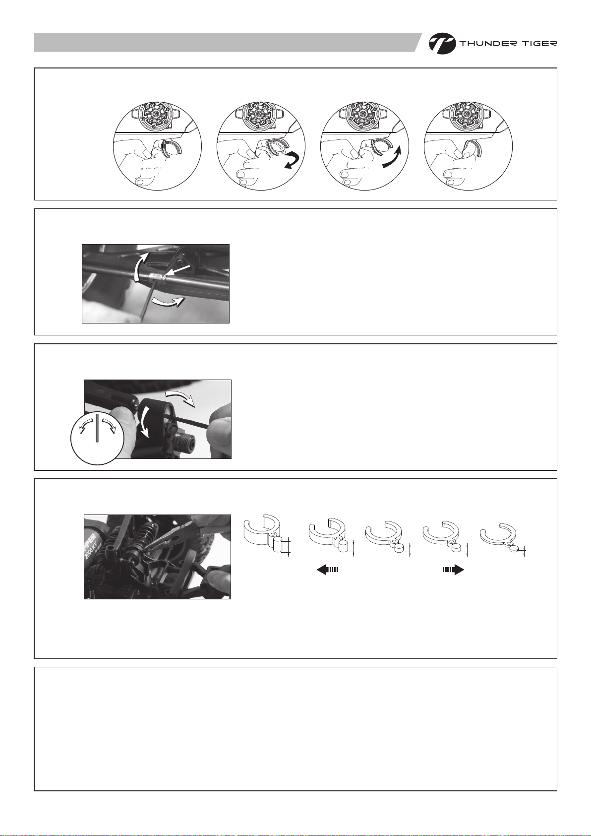
WHEEL AND TIRE PREPARATION 輪胎及輪轂
2
a
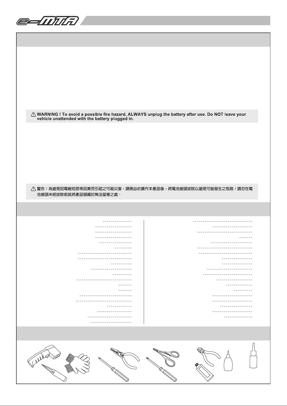
a. Remove wheel lock nut using the 4-way wrench and detach wheels.
b. Replace fresh tires and wheels if the original tires are worn out.
c. Tighten the wheel lock nut.
Make Sure The Axle Nuts Are Tight Before Each Run
Before operating your e-MTA, take a moment to make sure the axle nuts are tight,
as they may have loosened during shipping. The correct size axle-nut wrench is
supplied with the truck. Check the tightness of the axle nuts before each run. The
eMTA’s high speed and torque can loosen the nuts over time if left unchecked.
使用內附之六角螺帽套筒板手將輪轂上六角固定螺帽取下。
a.
b. 將已磨損嚴重之輪胎組取下後,換上新的輪胎組。
c. 將六角固定螺帽重新鎖緊。
輪胎鎖附步驟加註注意事項
在操作之前請先確認輪胎之固定六角螺帽是被鎖緊的。如未鎖緊,可使用隨車所附的螺帽套筒扳手將螺帽鎖緊。每趟跑完或是再次
出發前請務必檢查固定螺帽是否鬆脫?此車之高轉速與高扭力很可能於每一次的操作時使螺帽漸漸地鬆脫。
b
c
PREPARING THE CHASSIS 操作前,車體準備
3
4
a b
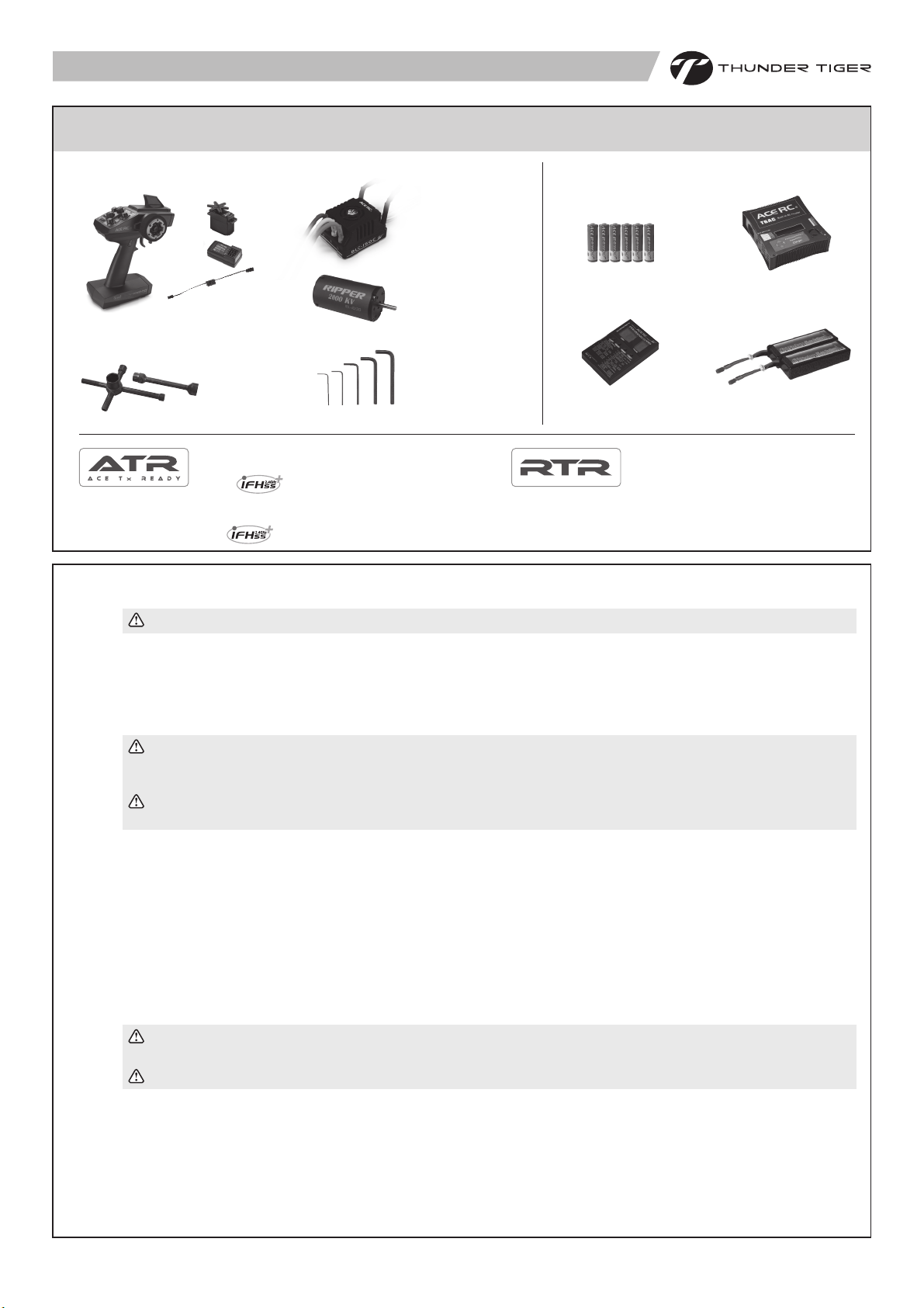
a. Remove the body pins (3 pcs.) and detach the body.
b. Straighten antenna and insert into antenna tube.
c. Put the antenna wire through the antenna pipe. (Do not cut or shorten
antenna wire.!) Push the antenna pipe into the chassis mount hole.
a. 將車殼固定插銷(共3個)拆除以取下車殼。
b.
c.
(請勿裁短天線以免影響接收距離)。
c
將天線穿套進天線管內。
將天線套管安裝於底板固定孔上
USING DIFFERENT BATTER CONFIGURATIONS 電池尺寸規範
30mm
a b
160mm
Std. battery
50mm
a. The battery compartments in the e-MTA are adjustable to accommodate many sizes of battery packs. From the factory, the
compartments are configured to accept the standard sized battery pack shown. (160 x 50 x 30mm)
b. The e-MTA battery compartments have adjustable battery retainer clips for keeping your battery secured. To adjust the battery
retainer clips, use a needle nosed pliers to pinch the releasing tabs of the clip.
c. Pull or push the battery retainer clips forward or backward to secure the battery in a balance position
accordingly in the battery compartments.
a. e-MTA的電池盒可以適應不同尺寸之電池。原廠建議使用為如圖示尺寸之電池。(160 x 50 x 30mm)
b. e-MTA電池盒內備有電池調整夾可協助固定不同尺寸之電池。
c. 使用方式為使用尖嘴鉗將調整夾上下向內夾緊,然後向外拉出或向內推擠以適應不同長度之電池並將
電池固定在左右相對平衡的位置上。
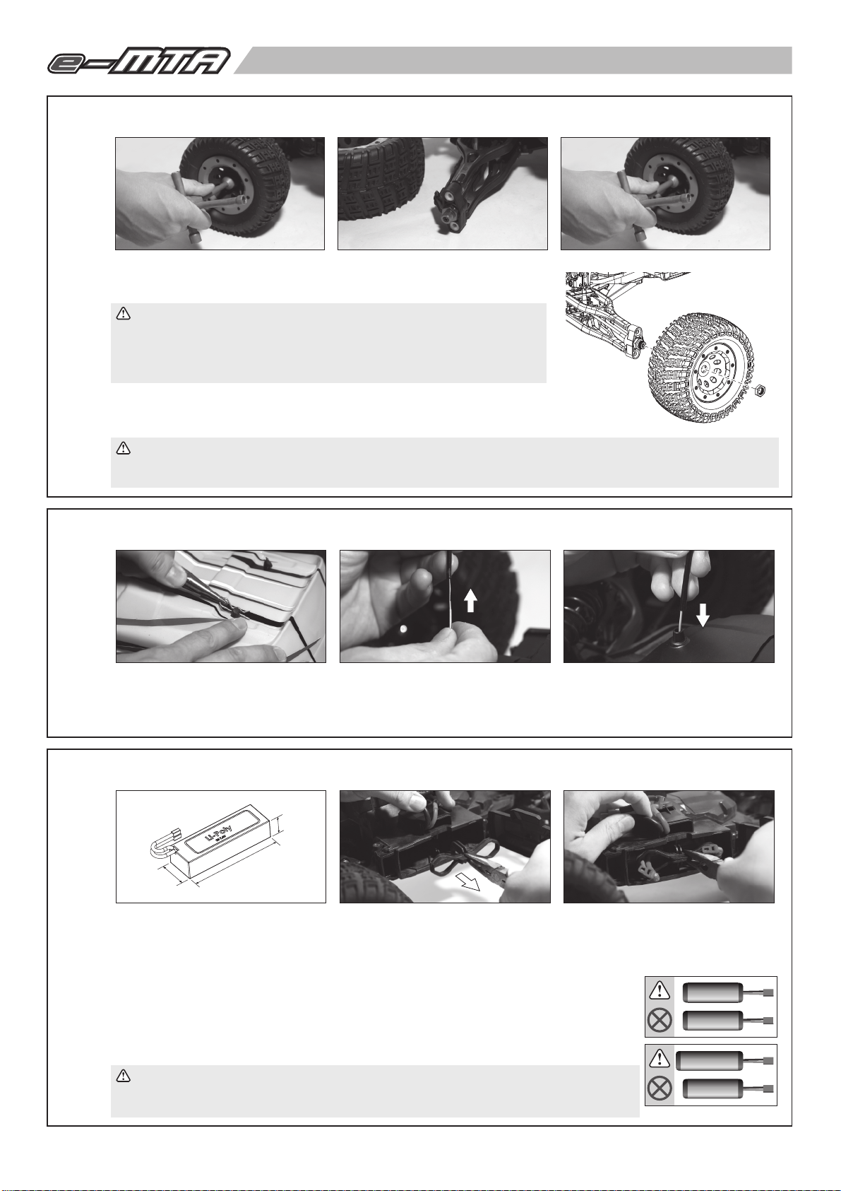
Do not mix battery types and capacities. Use the same voltage and capacity for both batteries.
Using mismatched battery packs could damage the batteries and electronic speed control.
切勿使用不同種類的電池或是不同電容量的電池搭配使用,此舉將會導致電池及電子速控器的損壞。
dimension
標準電池尺寸
c
1500
3600
3
Page 5
BATTERY INSTALLATION 電池安裝
(Batteries are not included in the kit. 本產品不含電池)
5
a b c
OFF 關
PUSH 按
d e f g
PULL 拉
a. Install 6pcs alkaline or rechargeable AA-size batteries into transmitter.
b. Make sure switch is OFF.
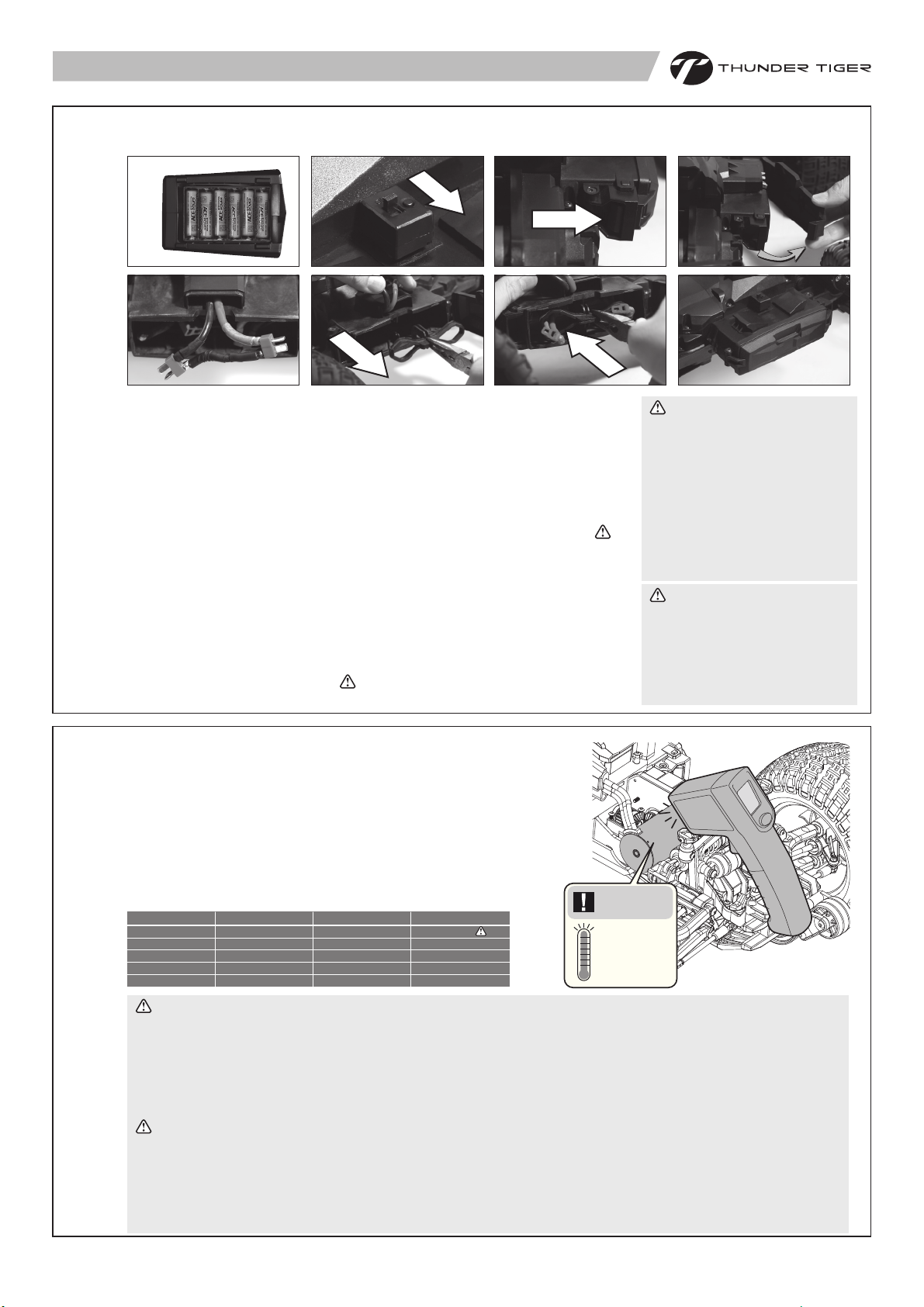
c. Open the battery compartment door by pressing on the releasing locks.
d. Install the battery packs with the battery wires facing the right side of the battery
compartment door.
e. Make sure the battery is sung in the compartment. If not, remove the battery and
make adjustment to the retainer clips.
f. Route the battery wires through the clips but do not connect with the speed control
at this time. (Note:always unplug the battery packs and remove from the model after use.)
g. Close the compartment door, making sure not to pinch the battery wires. Be sure
both release locks are fully engaged with the doors.
a. 安裝六顆三號鹼性電池或充電電池於發射機內。
先確認電源是關閉的。
b.
c.
向內按壓門扣即可打開電池盒的左右側門。
d.
安裝適當電池於電池盒中,電池出線面向電池盒的右側。
確認電池擺放位置正確。如不正確則重新調整電池至適當位置並用調整夾固定電池。
e.
f.
將電池出線穿過電池調整夾但不要在此刻連接速控器電源線。(注意:每次操作完畢,請將
電池與速控器電源線分離並取出電池。)
g. 關好並扣緊電池左右側門,注意不要折壓到電源線。
PUSH 推
Disconnect Batteries After Use
Always disconnect the batteries from
the speed control when you are
finished using your vehicle. The
switch on the speed control only
shuts off power to the receiver and
servos. The speed control continues
to draw power as long as it is
plugged in and may overdischarge
your batteries if they are left
connected to the speed control.
操作完畢注意事項
請務必於每次操作完畢後解除電子速控器
與電池的連結狀態。電子速控器電源開關
僅只關掉接收機與伺服機的電源供應。電
池內部電流消耗會因為電源線未拔離而持
續且可能會因此而過度放電而導致無法預
期的危險。
6
BATTERY CHART 電池使用選擇
Always adhere to the minimum and maximum battery limitations of the ESC as
stated in the specification table or instruction manual. (Ni-MH battery:6 to 14
cell , Li-PO battery: 4S to 6S). Remember your battery selection and
pinion/spur gear ratio determines your maximum speed.
Refer to the battery chart and select the type of batteries suit your driving skill.
請依循電子速控器所規定之電池使用之上下限制(鎳氫電池: 6-14顆,鋰電池: 4-6節)
請注意車子的最高速度是由電池與驅動齒比的選擇組合而決定。使用者請參考
下列電池表選擇適合自身操控技術的電池搭配。
Max. Speed
Pinion/Spur
Battery
Nominal Voltage
mAh
Skill Level
CAUTION: Read before operating your model with 25/51* ratio gearing! ( *51T spur gear is included in the kit)
• The 25/51 ratio for use with 6S LiPo batteries is designed for maximum speed (100 kmh) on smooth surfaces only, with
steady acceleration to full throttle.
• Avoid repetitive starting and stopping.
• Allow the motor to cool between runs, and monitor motor temperature.
• Do not use the 25/51 gear ratio for off-road running or motor overheating and damage may result.
• Do not allow the motor temperature to exceed (88° C)190° F or damage and motor failure may result.
注意:高速齒輪比25/51*加註事項:(*51齒大齒輪為隨車附送之改裝件)
• 25/51為高速齒輪比設定,如搭配6節鋰電將可達到時速100公里以上,此速度需要非常嚴謹之操控,請務必限制在平坦寬敞之
場地操作,操作時需慢慢漸進地將油門加到最大。
• 避免重複地急加速和急煞車。
• 操作期間請注意馬達溫度並於趟次之間進行降溫休息以保護馬達勿因過熱而縮短產品壽命。
• 請勿使用此25/51高速齒比於越野路面的操作使用,此舉可能引起馬達過熱及無法預期的損害。
• 馬達溫度請勿超過攝氏88度,否則馬達很可能因為過溫而導致退磁損壞。
65 kmh
25 / 55
twin 2s LiPo (4s total)
14.8V
5000+ mAh
Intermediate
100 kmh
25 / 55
twin 3s LiPo (6s total)
22.2V
5000+ mAh
Pro
100 kmh & Beyond
25 / 51
twin 3s LiPo (6s total)
22.2V
5000+ mAh
Pro+
Max temp
最大溫度
190°F
88°C
4
Page 6
THE ACE RC COUGAR GP3 熟悉2.4GHz電控系統
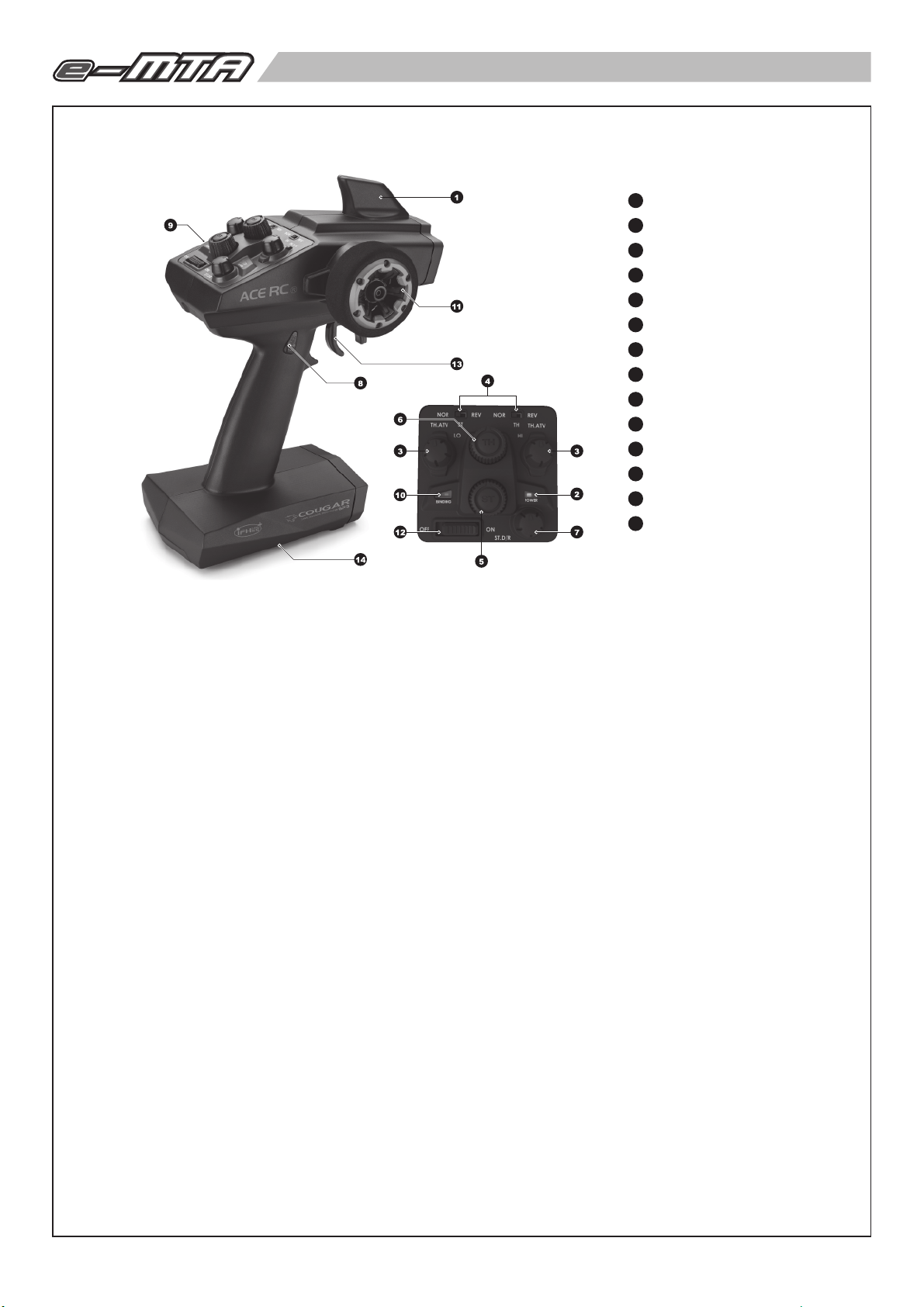
7
Transmitter Antenna
1
發射機天線
Battery Level Indicator
2
發射機電源顯示燈
HI/LO Throttle ATV (Adjustable Travel Volume)
3
高、低速油門行程調整鈕
Servo reversing switches
4
正逆轉設定裝置
Steering Trim
5
轉向微調鈕
Throttle Trim
6
油門微調鈕
Steering D/R (Dual Rates)
7
轉向大小動調整鈕
AUX Ch Button
8
第三動開關
External Charging Jack
9
充電孔
2.4GHz Binding / LED
10
2.4GHz校頻配對設定鈕
Steering Wheel
11
轉向舵輪
Power Switch
12
電源開關
Throttle Trigger
13
油門控制板機
Battery Cover
14
電池蓋
TRANSMITTER CONTROLS
1. Transmitter Antenna: Built-in antenna, it is not easy broken.
2. Battery Level Indicator: Green / Red LEDs indicate the battery voltage. If the Red LED flashes, please replace the batteries.
3. HI/LO Throttle ATV (Adjustable Travel Volume): Provide the function to let you independently preset the maximum travel of
the throttle servo either side (high / low) of neutral.
4. Servo reversing switches: To reverse the servo's rotation direction at the flip of the switch. The reversing switches are
recessed into the transmitter to prevent accidental operation.
5. Steering Trim: Adjusts the steering in small increments or decrements to run the model straight.
6. Throttle Trim: Adjusts the throttle in small increments or decrements to shift the neutral position.
7. Steering D/R (Dual Rates): Turn this knob left or right to adjust the amount of the steering dual rate. Right to increase dual rate
amount and left to decrease the amount.
8. AUX Ch Button: Provides an extra function for the control of the model. (for Cougar GP3 only)
9. External Charging Jack: For rechargeable NiCd/NiHM battery pack on the transmitter only.
10. 2.4GHz Binding / LED: The Binding button is located on the top of the 2.4GHz transmitter. For additional details, please refer to
the “Binding” setting procedure (Page 6). LED indicate the RF status. The Red LED means RF funtion is not work.
11. Steering Wheel: Control the steering of the model.
12. Power Switch: Slide to turn the transmitter on or off.
13. Throttle Trigger: Pull or push to control the movement of the model.
14. Battery Cover: Slide cover to install or remove batteries.
發射機各部功能簡介
1. 發射機天線:內建式發射機天線不容易損壞。
2. 發射機電源顯示燈:二顆LED設計顯示發射機電池殘量,若紅色LED燈閃爍時,請更換發射機電池。
3. 高、低速油門行程調整鈕:獨立調整高、低速油門行程量功能。
4. 正逆轉設定裝置:依實際使用,控制伺服機作動方向。
5. 轉向微調鈕:利用此旋鈕,調整設定轉向正確中立點位置。
6. 油門微調鈕:利用此旋鈕,調整設定油門正確中立點位置。
7. 轉向大小動調整鈕:調整轉向伺服機的行程量。
8. 第三動開關:第三動功能開關按鈕。(Cougar GP3 適用)
9. 充電孔:使用充電式電池時,可利用此充電孔,進行充電工作。
10. 2.4GHz 校頻配對設定鈕:2.4GHz之BINDING SW校頻配對設定鈕,為配對發射/接收頻率之用。更多功能設定方式請參考說明
書第6頁“校頻配對步驟”。
11. 轉向舵輪:控制車輛轉向裝置
12. 電源開關:發射機電源開關
13. 油門控制板機:控制車輛前進或後退的裝置
14. 電池護蓋:推移電池護蓋即可取出電池進行更換。
5
Page 7
BINDING PROCESS 安全校頻配對(鎖碼)
8
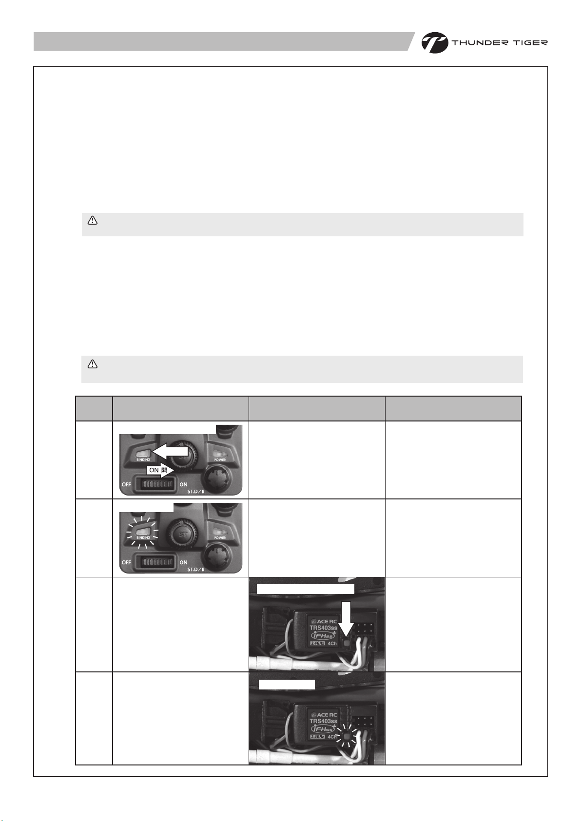
A binding feature is included in the ACE RC Cougar 2.4GHz spread spectrum system to ensure the transmitter and receiver bind
properly and prevent interference from other controllers.
To manually bind Tx/Rx, please proceed as per the following steps:
a. Press and hold the “Binding” button on the upper side of the transmitter while turning on the transmitter.
b. Release the “Binding” button after the green LED flashes indicating the transmitter is binding.
c. Press and hold the bind button on the receiver while turning on the receiver. Binding process will then start automatically.The
LED will turn green/reed flash on the receiver.
d. Release the “Binding” button. Successful binding is confirmed by the binding LED changing from a quick blinking and then
remain solid on the transmitter. The LED will turn green on the receiver. Once binding is complete, the system will
automatically connect.
Note ! Binding process may take 2~4 seconds to execute. If binding fails, the LED on the receiver will turn red.
Please turn off the power and repeat the steps from a) ~d).
ACE RC Cougar GP3 採用最先進的專用3動2.4GHz無限展頻遙控系統。這個系統結合發射與接收可以互動溝通模式,跳動頻道
搜尋,使得整體無線遙控系統的傳輸展現準穩定的特性,同時也無須擔心頻率干擾的問題。如發現無法操控情形發生,需要重新
校頻配對,請依照下列步驟重新進行校頻配對程序:
a. 打開發射機電源時,同時持續按壓發射機之 "Binding" 按鈕。
b. 直按鈕旁之LED綠燈快速閃爍,再放開 "Binding" 按鈕,表示發射機正在進行自動搜尋校頻,此時請不要關閉發射機電源。
c. 然後按壓接收機上之 "Binding" 按鈕並同時開啟接收機電源,此時接收機將自動進行校頻配對程序。接收機LED燈號為紅綠快速
閃爍。
d. 放開 "Binding" ,一旦完成配對程序,發射機LED燈號會從綠色快速閃爍轉換成持續綠色燈號,接收機LED燈號將從紅色轉換為
綠色。此時表示接收機與發射機已完成配對溝通,可以進行操控。
注意!遙控系統校頻配對可能需要 2~4 秒執行程序。如果程序執行錯誤,發射及接收模組的 LED 燈號將持續呈現紅色。請
關閉電源再依 a)~d) 的順序重新操作配對程序。
Step
步驟
a
b
c
d
TX Action
發射機動作
Swithch On 開 / Press 按
Press
按
Release 放開
No Action
無須動作
No Action
無須動作
RX Action
接收機動作
No Action
無須動作
No Action
無須動作
Swithch On 開 / Press 按
Release 放開
按
Press
LED
燈號
_
TX LED:Green Flash
TX 燈號:綠燈快速閃爍
RX LED:Green/red Flash
RX 燈號:綠/紅燈快速閃爍
TX LED:
Green Flash --> Green Solid
RX LED:
Red Solid --> Green Solid
TX 燈號:
綠燈快速閃爍 --> 綠燈亮
RX 燈號:
紅燈亮 --> 綠燈亮
6
Page 8
FAIL SAFE(F/S) FUNCTION SETTING 安全回復功能設定
9
ACE RC COUGAR 2.4GHz R/C system features a built-in Failsafe function to automatically set a servo command if the receiver
loses the signal from transmitter due to interference. For safety, we strongly recommend to active the FAILSAFE function on
your Cougar R/C system.
Setting up the Failsafe (F/S) Function:
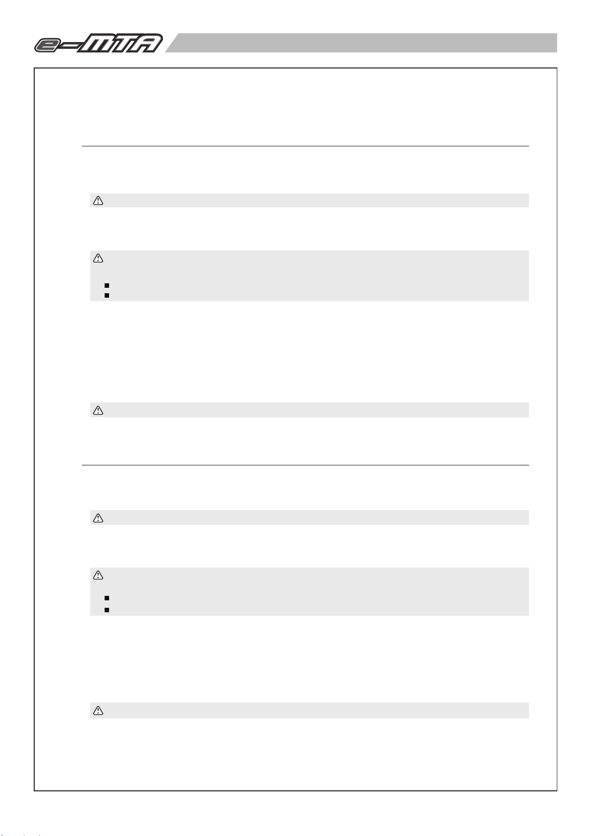
a. After binding the transmitter and receiver, you can continually set up the F/S function. Turn on the transmitter power and then
receiver power.
b. Press and hold the “Binding” button on the receiver for 10 seconds. The LED will start flashing GREEN on the receiver.
CAUTION ! Do not release the “Binding” button on the receiver until STEP C is completed.
c. Move and hold the throttle trigger to the position you want the control to be in if a failsafe condition should occur. First, keep
steering wheel at neutral position(steering servo at neutral position). To set up F/S function with the throttle servo position
at "Brake", first push the trigger to the brake position and hold. To set up F/S function with servo position at "Neutral", keep
the trigger at neutral position.
NOTE ! Always set the throttle trigger to neutral or full brake position and steering servo to neutral position in
case of any unexpected control error !
Factory pre-settings for RC car F/S function are :
Electric Car - Steering servo at neutral, throttle at neutral.
Nitro Car - Steering servo at neutral, throttle at iddle and car brakes.
d. After the Step C, release the “Binding” button on the receiver first and then the throttle trigger. The LED turns to solid “RED”
e. Test by turning off your transmitter and watching the servo failsafe position activate.
F/S at "Neutral" : To check the fail safe is working properly, by moving the throttle trigger to the full forward (full brake), hold
F/S at "Brake" : To check the fail safe is working properly, by keeping the throttle trigger at neutral and then turn off the
f. If the F/S function fails or need to change the F/S hold position, repeat the steps a) ~e). After the F/S is completed, you can
and then back to solid “GREEN” indicating the F/S function has now been activated.
this position and then turn off the transmitter. The F/S function should move the throttle servo to “Neutral” position and the
steering servo to “Neutral” position.
transmitter. The F/S function should move the throttle servo to “Brake” position and the steering servo to “Neutral” position.
start normal operation.
CAUTION ! ALWAYS reset FAILSAFE function after binding your transmitter & receiver.
ACE RC COUGAR 2.4GHz 遙控系統內建安全回復功能,可設定接收機因干擾或斷電而失去發射機訊號時,伺服機自動回復至預
設位置。安全起見,強烈建議您務必啟用安全回復功能。
安全回復功能設定
a. 設定此功能前請先完成系統發射與接收之對頻。確定後,先打開發射機再開接收機電源。
b. 按壓著接收機對頻開關,約10秒鐘後LED會變為綠色快速閃爍。示進入F/S設定模式。
注意!C步驟完成前不要放開接收機對頻鍵。
c. 同時移動油門扳機至您想要設定F/S伺服機位置。轉向輪請保持中立點位置。
【如想要設定F/S油門伺服機位置為煞車,需先移動油門扳機至煞車位置不要鬆開。】
【如想要設定F/S油門伺服機位置為中立,請保持油門扳機在中立點位置。】
注意!油門伺服機安全回復位置建議設定為煞車或中立點,請勿設定為油門開啟位置,以免發生危險。本系統出廠預設
F/S 功能如下:
電車﹣轉向伺服機位置在中立點,速控器油門在靜中立點。
油車﹣轉向伺服機位置在中立點,油門伺服機在怠速位置。
d. 此時你可以放開接收機對頻鍵,然後再放開發射機油門板機。LED會變為亮紅燈,約2秒後又回亮綠燈,此時示F/S功能已經設
定完成。
e. 檢查動作:
F/S油門伺服機位置設定為中立點: 將油門扳機全煞車,關掉發射機電源,檢視F/S伺服機位置動作是否轉回中立點位置。
F/S油門伺服機位置設定為煞車: 油門扳機保持中立點,關掉發射機電源,檢視F/S伺服機位置動作是否轉回煞車位置。
f. 檢查無誤後,開發射機開關,然後接收機關開始操作。
注意!重新對頻後,請務必重新設定安全回復功能。
7
Page 9
Step
步驟
a
b
c
TX Action
發射機動作
Binding Complete
完成對頻
No Action
無須動作
1. Steering: Neutral
2. Keep brake or trigger at neutral
1.
1.
轉向中立
2.
保持煞車或是油門在中立點
2.
or
Neutral
中立Neutral 中立
RX Action
接收機動作
Binding Complete
完成對頻
Push for 10
Push for 10
Sceonds
Sceonds
持續按10秒
持續按10秒
Switch on Power
Switch on Power
開啟電源
開啟電源
No Action
無須動作
按
Press
LED
燈號
TX LED: Green Solid
RX LED: Green Solid
TX 燈號:綠燈亮
RX 燈號:綠燈亮
RX LED: Green Flash
RX 燈號:綠燈快速閃爍
Pre-settings for F/S function:
EP Car : Steering at Neutral /
出廠預設F/S功能:
電車:轉向朝前,速控器煞車
ESC at Neutral
d
e
f
RADIO OPERATION 遙控器操作
10
Release Later
後放開
1. Keep Brake
2. Swithch Off
1. 保持煞車
2. 關發射機
Release First
1.
2.
No Action
OFF
無須動作
先放開
RX LED:
Red Solid-2s --> Green Solid
RX燈號:
紅燈亮-2秒 --> 綠燈亮
F/S Function Activates
F/S 安全回復功能啟用
OK!
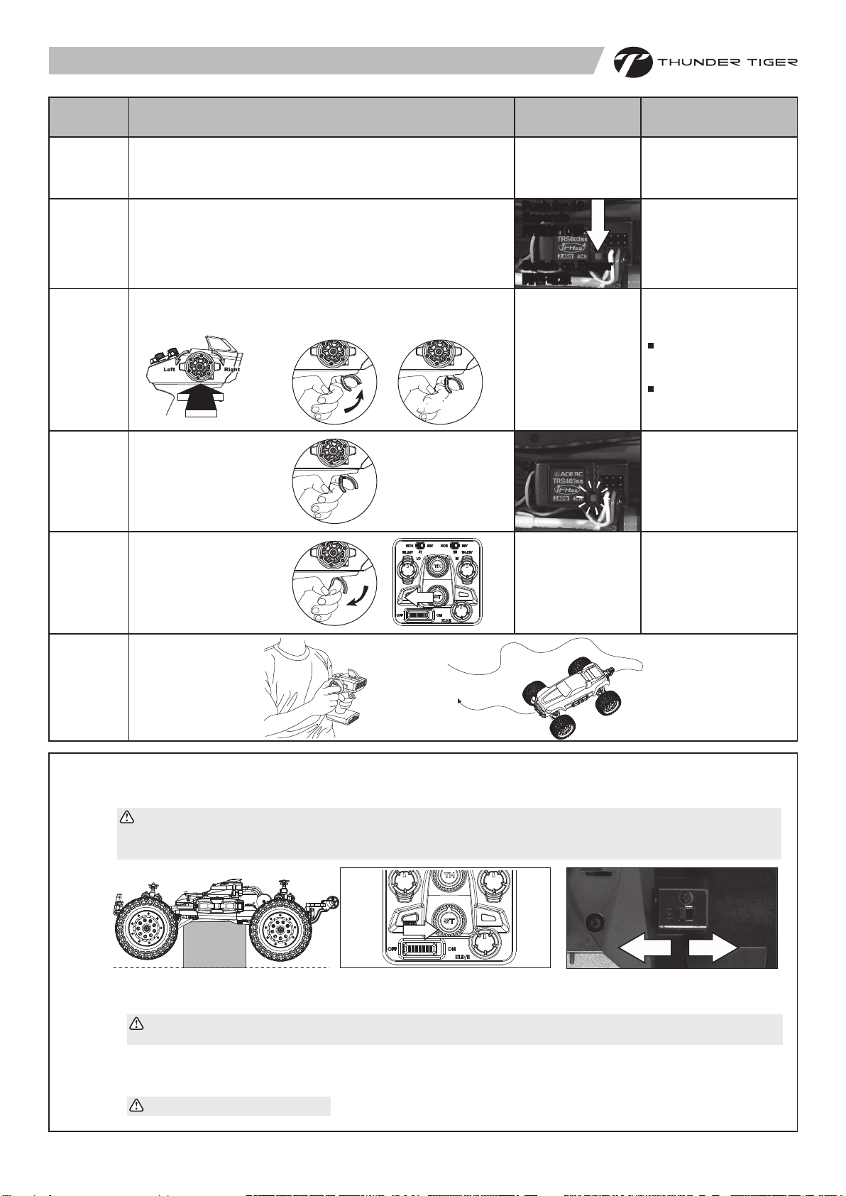
WARNING: The brushless system is very powerful. For safety, please always keep the wheels away from the track
when you are preparing to switch on the car.
注意:本系統功率十分強勁!基於安全因素,建議請在車輪懸空的裝態下開啟系統電源,避免非預期性的暴衝。
ba
ON 開
開
OFFON
When turning radio system on. Turn the transmitter on first, then turn on the ESC.
a.
b. When turning the radio system off. Turn the ESC off first, then turn off the transmitter.
Caution ! Do not run the transmitter's battery flat or you will lose control of the car. For additional details, please refer
to the transmitter instruction manual.
a.
為避免車子失控暴衝,先開啟發射機電源。
b. 接著開啟速控器電源。電源的關閉則是相反的順序,先關速控器電源,再關發射機電源。
其他注意事項請參考發射機說明書。
8
關
Page 10

OPERATING RADIO STEERING FUNCTION 遙控器設定-轉向
11
a b
a. Check the radio steering functions. With the radio transmitter and receiver on, turn the steering wheel to the left. The front tires /
wheels should turn left accordingly. If not, flip the steering servo reverse switch.
b. Return the steering wheel to neutral. The front tires/wheels should point straight forward. If not, use the steering trim lever to
correct it.
c. Turn the steering wheel to the right. The front tires/wheels should turn right accordingly.
a.
確認轉向功能。打開發射機及接收機電源,方向轉左邊時,輪胎將朝向左邊,若方向不一致,請調整方向的正逆轉開關。
b. 方向回中立點時,前輪應筆直向前,若有偏差,請調整方向微調旋鈕。
c. 方向轉向右邊時,前輪應轉向右邊。
ADJUSTING SLIPPER CLUTCH SYSTEM 限滑器(滑動離合器)
12
a b
The e-MTA is equipped with an adjustable slipper clutch which is built into the large spur gear. The purpose of the slipper clutch is to
regulate the amount of power send to the wheels to prevent tire spin. When it slips, the slipper clutch makes a high-pitch, whining noise.
a. To adjust the slipper, use a screwdriver to stop the rotation of the spur gear. For the first time adjustment, taking off the spur gear
cover is necessary and convenient for observation.
b. Then use the included cross wrench to hold the adjusting nut and turn clockwise to tighten or turn counter-clockwise to loosen.
c. Factory Default: Turn the adjusting nut clockwise until the nut touches the circular washer as a starting point。Turn another 1/4
turn clockwise for the factory set-up. Do not turn the slipper clutch adjusting circular washers fully compressed. The maximum
slipper clutch setting is another 1/2 turn clockwise from the starting point as the nut touches the circular washer. If the slipper
clutch is too tight, it may damage the drive train.
e-MTA 於大主齒外側配備可調式限滑器,而限滑器 (Slipper clutch 也叫滑動離合器),可以讓你調整從馬達傳遞到車輪的最大的扭力
,以適應低抓地力的路面。可避免車子在瞬間起動或加速時,因動力過大而產生的打滑現象。
a. 你可以使用隨車所附的四向螺帽套筒調整扭力輸出大小。先使用一支螺絲起子將驅動大齒輪卡住使之無法旋轉,並將螺帽套筒置
於限滑器最外端的螺帽上。第一次調整時,將齒輪蓋拆下將有助於觀察與調整。
b. 順時針方向為鎖緊限滑器,逆時針為鬆開限滑器。
c. 出廠調整值為螺帽旋入與盤型彈簧接觸後再鎖入約1/4圈。注意:螺帽勿鎖入超過1/2圈(與盤型彈簧接觸為起點)。當螺帽鎖入過
多,將使扭力限制器無法在適當時機做動,造成傳動系統損壞。
The maximum slipper clutch setting is another 1/2 turn
clockwise from the starting point as the nut touches
the circular washer. If the slipper clutch is too tight, it
may damage the drive train.
調整方式:螺帽旋入與盤形彈簧接觸後,再鎖入約1/4圈。
注意:螺帽勿鎖入超過1/2圈。當螺帽鎖入過多,將使扭力
限制器無法在適當時機作動,造成傳動系統損壞。
Take off
拆下
Tighten鎖緊
Loosen
Slipper
Clutch
鬆
Tighten
Slipper
Clutch
緊
c
c
STOP 停止
1/2 Turn 180
Max. Torque 15kg/cm
約15公斤/公分
Start Point 0
調整起始點
。
1/4 Turn 90
Std. Torque 11kg/cm
約11公斤/公分
。
。
ADJUSTING THE ESC
Before adjusting the ESC, read the instructions for the ESC first.
13
調整電子速控器前,請先詳閱電子速控器的操作說明。
速控器調整
9
Page 11
DRIVING BASIC 操控基本動作
14
FRONT & REAR TOE-IN / TOE-OUT
15
FRONT & REAR CAMBER 前後輪傾斜角調整
16
Add Pos.
Camber
正傾角
Add Neg.
Camber
負傾角
Stop (Neutral)
Stop (Neutral)
停(中立點)
停(中立點)
Notch
刻槽向內
Brake
Brake
煞車
煞車
Reverse
Reverse
後退
後退
Acceleration
Acceleration
加速
加速
前後輪束角調整
a.
Use a 1.5mm Allen wrench as shown to adjust the front & rear toe-in.
b.
Lengthening the Turnbuckles will increase the amount of toe-in, shortening them will
increase the amount of toe-out.
c. The notch on the turnbuckle indicates the side that has the right-hand thread. Use it
as a guide to determine which way to turn the turnbuckle when adjusting its length.
使用1.5mm六角扳手調整前、後輪束角。
a.
b.
增長螺距將會增加內束角角度;縮短螺距將會增加外束角角度。
請參照本說明調整您愛車前、後輪的傾角。
a.
Use a 2.5mm Allen wrench as shown to adjust the front & rear camber.
Turning the upper pivot ball clockwise increases camber towards the negative
b.
side; turning it counter-clockwise increases camber towards the positive side.
使用2.5mm六角扳手調整前、後輪傾斜角(如圖示)。
a.
b.
調整上輪軸球頭順時針旋轉將增加負傾斜角;反之,將增加正傾斜角。
請參照本說明調整您愛車前、後輪的傾角。
SHOCK ADJUSTMENT 避震器懸吊調整
17
MAINTENANCE AFTER RUNNING 車體保養
a. Always turn off the radio system and disconnect the battery pack when the car is not in use.
18
b. Remove sand, mud, dirt, and any other elements before storing the car.
c. Never use chemicals or any solvents to clean the chassis as it may cause damage to the electronics components and plastic parts.
Use compressed air, soft paintbrush, or toothbrush to clean dust and dirt.
a.
結束操控儲存車體前,請謹記要關閉電源,並將電池接頭拔除,以免電池短路造成不必要之危險。
b. 清潔車體上所沾附之沙塵、泥屑。
c. 請勿使用化學清潔劑來清洗底板,以免遙控之電子設備受潮、電線、焊點及膠件被侵蝕而導致不必要之損壞。清潔車體時,請儘量
使用強力之壓縮空氣,搭配軟毛刷來請清理車體上所沾附之沙塵、泥屑。
10mm
Hard Suspension
懸吊較硬
a. The truck ride height can be increased by adding preload clips to the shocks.
Removing preload clips will decrease the ride height.
b. Compress the spring and insert the preload clips between the spring collar and the
shock body flange.
a. 車身高度可利用避震器調整墊片改變。增加調整墊片可增加車高;反之則降低車高。
b. 安裝或拆卸墊片時,請壓縮避震器彈簧再置入或取出墊片即可。
5mm
2mm3mm
Soft Suspension
懸吊較軟
1mm
10
Page 12

DRIVING TIPS 操控的小技巧
19
a. Hold your elbows in and keep the
transmitter antenna pointing straight up.
a. 手持發射機時請將雙肘靠緊身體並保持
發射機天線朝上。
d.
If you are of unsure of the steering
direction, practice with the
transmitter facing towards you.
d.
假設你不確定發射機的轉向,將發射
機轉輪面向自己,先熟悉左右轉向。
Squeeze the throttle trigger or pull
b.
the throttle stick gently and steer the
car to left and right.
b. 開始操控前按扣油門板機(油門拉)時
請緩慢增加油門並試著熟悉前輪轉向
操作。
e. At first, set the steering D/R function
for less steering response.
e. 學者可參考發射機說明書調整D/R功
能,以避免轉向太過靈活不易操控。
c. Squeeze the throttle trigger and
release. Repeat this action to control
car speed.
c. 學者請先熟悉油門操控再慢慢加快車
子行進速度。
Be careful not to squeeze the throttle
f.
trigger abruptly while steering.
f. 轉向時請勿將油門全開以避免速度過
快導致失控翻覆。
g.
After you become used to the controls, experiment with high
performance possible at full throttle and full steering.
g. 熟悉前述基本操控後再試著將油門全開進行高速操控。
11
h.
Practice doing figure 8S.
h. 建議可以使用繞8字來熟悉發射機操控動作。
Page 13

TROUBLESHOOTING 常見問題與解決方 法
If you have trouble starting or keeping your e-MTA running, here's a quick checklist of what to look for first.
如果您的 e-MTA 有行駛上的問題,您可以參考下的說明。
如果問題無法解決,請與購買經銷商聯絡。
Description 問題
Car dies or slows
車不動或速度變慢
Car is glitching
車故障
Motor overheats
馬達過熱
No power
失去電力
No throttle
失去動力
Problem 可能原因
Speed control over heats
速控器過熱
Car has a problem on power
車子的動力有問題
Gear mesh is too tight
馬達驅動齒輪太緊
Battery is discharged
電池沒充電
Battery not plugged in
電池沒接好
Motor not plugged in
馬達連接線沒接好
Motor failure
馬達損壞
Motor keeps running
未扣引發射機油門,馬達卻持續轉動
Solution 解決方法
Let it cool and try later
先冷卻,稍後再試
Check for loose wires, dead radio batteries.
檢查電線是否脫落或遺失
Let motor cool and check recommended gearing for motor
type. Reset gear mesh
先讓馬達冷卻,再重新調整合適的齒隙
Charge battery
將電池充電
Plug battery in
將電池接頭確實連接遙控車
Plug motor in
確實接上紅、黃、黑端之馬達電源傳輸線(紅對紅、黃對
黃、黑對黑)
Replace motor
置換新馬達
Check if the throttle trim is in neutral position.
檢查是否油門微調不在中立點的位置
No steering
失去控制
Reversing
後退功能
Servo not plugged in
轉向伺服機未安裝好
Locked up steering linkage
轉向裝置卡死
Servo failure
伺服機失靈
Goes backwards when you pull the
trigger or goes right when turning the
wheel left
當扣引/放開發射機油門板機,車子卻
後退/前進或是發射機方向轉輪之轉向
跟車子轉向左右相反
Plug servo into ESC unit
將連接電線接上速控器
Free up steering linkage
排除可能的干涉(卡)的零件部
Replace servo
置換新伺服機
Check throttle / steering reversing switches on transmitter
檢查發射機上之油門/轉向的反轉開關是否反轉?
12
Page 14
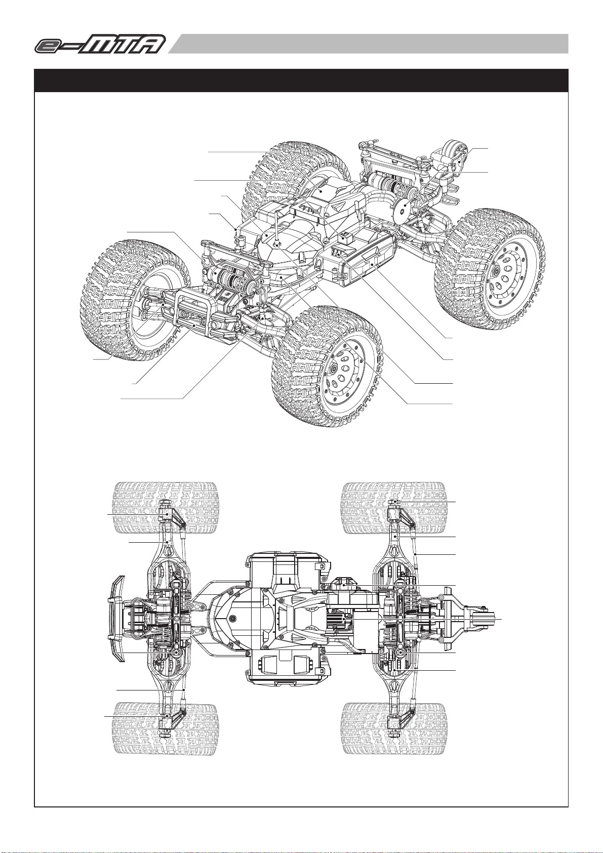
Product Overview
產品概要
ESC Compartment 速控器盒
ESC Switch 速控器開關
Receiver Compartment 接收機盒
Battery Compartment 電池盒
Oil Shock 油壓避震器
Front CVA
前萬象傳動軸
Front Bumper 前防撞桿
Push Rod 避震連桿
Rear Wheelie Bar
後翹輪桿
Brushless Motor
無刷動力馬達
Battery Compartment Door
電池盒蓋
Battery Compartment Vent
電池盒散熱孔
Antenna Mount 天線座
Servo Compartment 伺服機盒
Knuckle 球頭座
Front Suspension Arm
前擺臂
Front Body Mount
前車殼固定座
Toe-Link 投影拉桿
Pivot Ball 球頭
Hex Hub 六角輪座
Rear Suspension Arm 後擺臂
Toe-Link 投影拉桿
Slipper Clutch 限滑器
Transmission
齒輪箱
Rear Body Mount 後車殼固定座
Rear CVA 後萬象傳動軸
13
Page 15
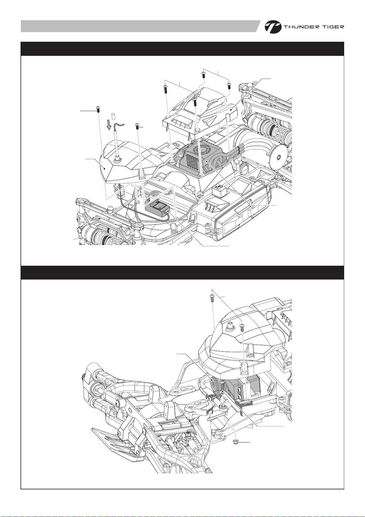
Radio and ESC Maintenance
PD0669
M3x12mm
Receiver Antenna
Installation
接收天線安裝
PD1036
M3x8mm
PD1036
M3x8mm
PD09-0090
遙控及電子速控器維修
PD1036
M3x8mm
PD09-0091
ESC (Electronic Speed Control)
電子速控器
Servo Maintenance
Receiver 接收機
電子伺服機維修
PD1036
M3x8mm
Servo 電子伺服機
14
PD0671
M3x16mm
PD0971
Lock Nut M3
Page 16
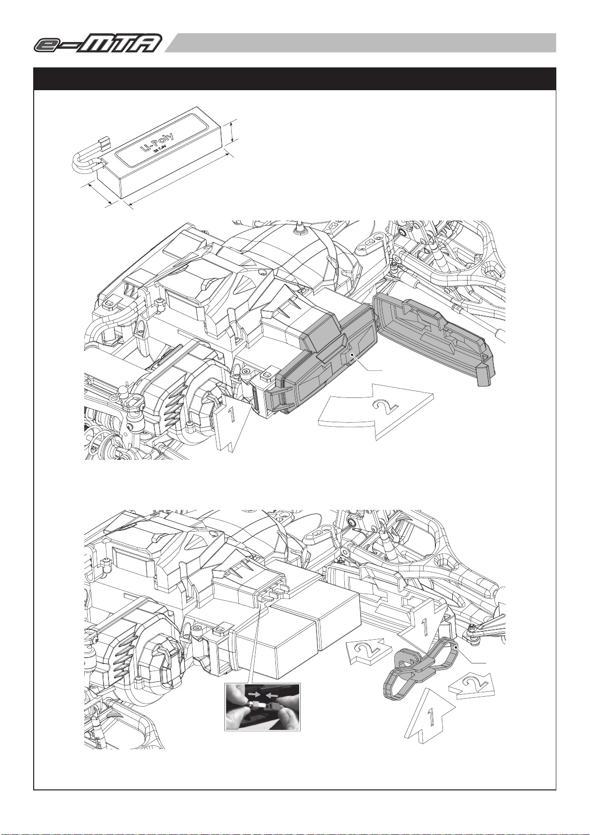
Battery Installation
電池安裝
Standard Battery Dimension
標準電池尺寸規範
50mm
30mm
160mm
PD09-0083
PUSH 按
Make sure the ESC is turned off before connecting the battery.
接通電源前,請先確速控器處於關閉狀態。
OPEN 開
PD09-0082
Use the battery clip to keep your batteries secure.
Don’t pinch the wires in the battery compartment.
使用電池調整夾固定電池
關閉電池盒蓋時,請勿壓折到電源線。
15
Page 17

Wheel Maintenance
輪胎維修
STEP1
Wheel Installation 安裝輪胎
PD10-0048
STEP2
PD05-0028
Pin 2.5x16mm
PD8324
PD1962
Set Screw M3x4mm
Pivot Hub Carrier Maintenance 球頭輪座維修
PD1498
PD1572
PD1498
PD1577
PD1499
PD1745
PD8325
PD1572
PD1746
16
Page 18

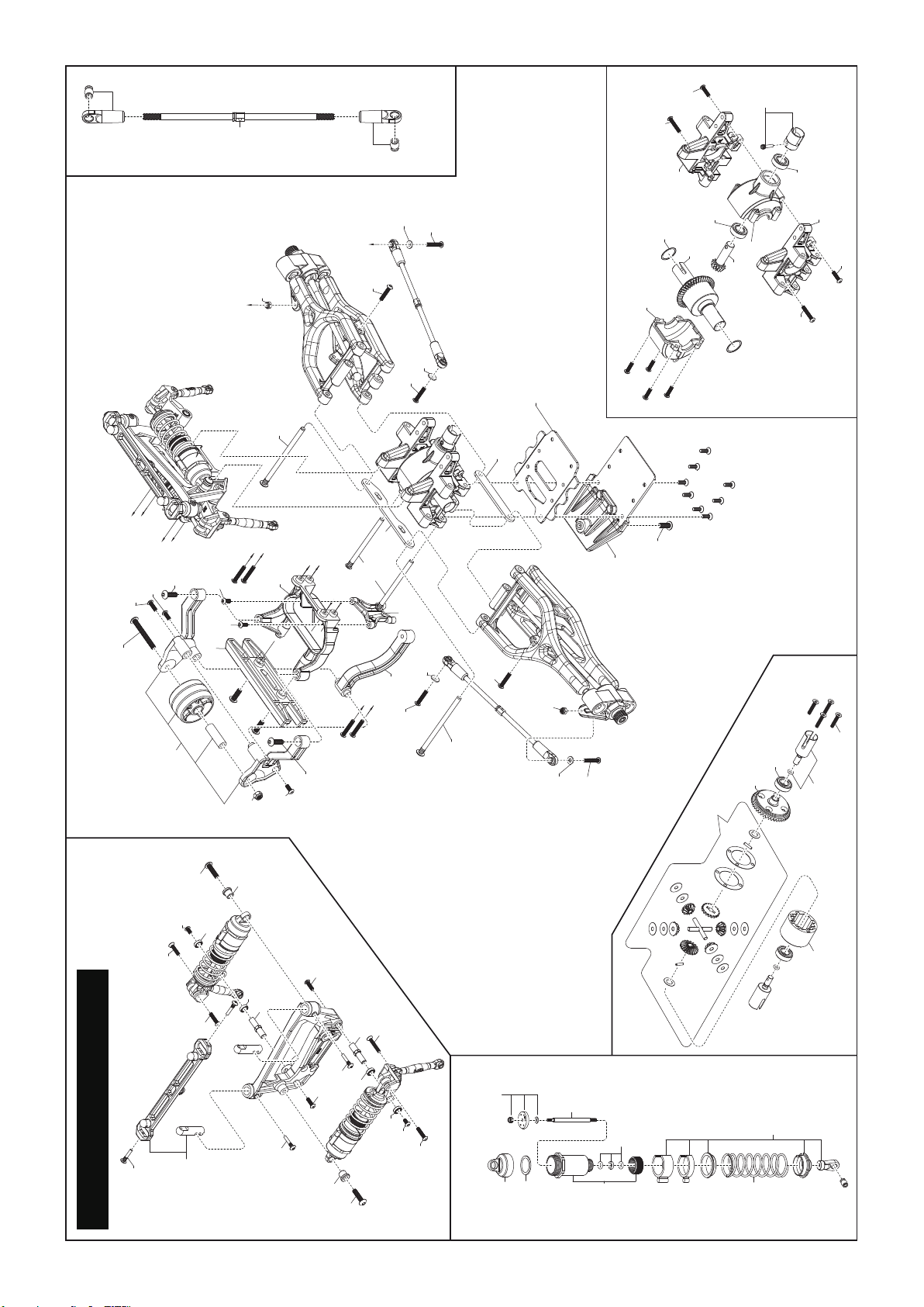
Front Suspension Maintenance
前懸吊維修
STEP1
PD0671
M3x16mm
PD9316
M4x12mm
STEP2
PD0671
M3x16mm
STEP3 STEP4
PD0672
M3x18mm
PD0678
M3x10mm
PD9010
M4x14mm
17
Page 19

Front Suspension Maintenance
前懸吊維修
STEP5
PD9010
M4x14mm
PD0669
M3x12mm
PD1709
Washers M3
STEP6
PD0672
M3x18mm
PD0678
M3x10mm
PD0672
M3x18mm
PD1709
Washers M3
PD0971
Lock Nut M3
STEP7
STEP8
PD0669
M3x12mm
PD1497
PD0672
M3x18mm
PD0971
Lock Nut M3
PD09-0068
PD09-0068
PD0672
M3x18mm
18
PD0669
M3x12mm
Page 20

Rear Suspension Maintenance
後懸吊維修
STEP1
STEP3
PD0910
M4x14mm
STEP2
STEP4
PD0910
M4x14mm
PD09-0081
PD09-0075
PD9316
M4x12mm
STEP5
PD0671
M3x16mm
PD0671
M3x16mm
PD1709
Washers M3
STEP6
PD0669
M3x12mm
PD0672
M3x18mm
PD0672
M3x18mm
PD09-0069
PD09-0075
PD0671
M3x16mm
PD09-0069
PD0669
M3x12mm
PD0672
M3x18mm
PD1497
19
Page 21

Differential Maintenance
差速維修
STEP1
PD1456
PD1571
PD02-0023
PD1482-1
PD1571
PD1481
PD1896
STEP2
PD6341-1
PD0681
M3x16mm
Grease
潤滑油(黃油)
PD0669
M3x12mm
STEP3 STEP4 STEP5
PD6343
PD1571
PD6341-1
PD6341-1
PD6341-1 PD6341-1
PD6342
PD1571
PD6341-1
PD1749
PD1749
20
Page 22

Shock Maintenance
避震組維修
Front Shock & Push Rod / Rocker Arm 前避震器及推桿/搖臂
STEP1
PD9319
M4x16mm
PD0671
M3x16mm
PD0671
M3x16mm
STEP2
PD9319
M4x16mm
PD05-0036
PD09-0072
PD9130
PD0666
M3x6mm
PD0671
M3x16mm
Rear Shock & Push Rod / Rocker Arm 後避震器及推桿/搖臂
STEP3
PD9319
M4x16mm
PD05-0036
STEP4
PD1035
M3x10mm
PD05-0029
PD9130
PD03-0023
PD1035
M3x10mm
Shock Assembly 避震器組裝
STEP5
PD07-0020
PD07-0013
PD0680
M3x14mm
PD0666
M3x6mm
PD9319
M4x16mm
STEP6 STEP7
PD07-0014
PD07-0017
PD07-0025
Silicon Oil
矽油
Recommended Shock Oil
建議矽油番號
45wt / 575cst
PD9130
PD09-0073
PD03-0023
PD05-0029
PD1035
M3x10mm
PD07-0020
PD07-0024
21
PD07-0037
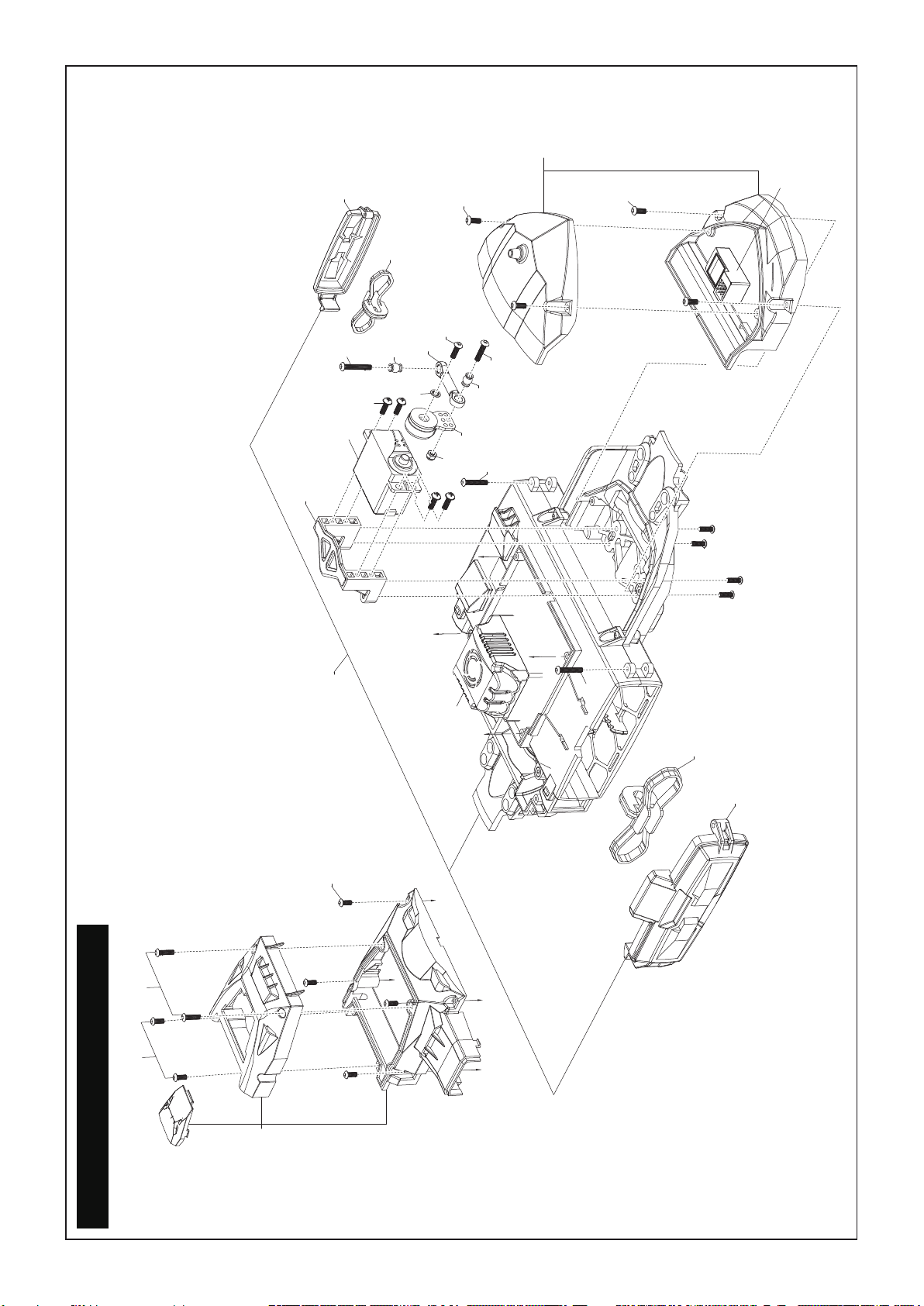
Page 23

Slipper Clutch Maintenance
限滑器維修
STEP1
Take off the gear cover 取下保護蓋
Install a sheet of paper to adjust proper gear mesh.
可插入紙片來調整適當齒輪間隙
PD0666
PD0666
M3x6mm
M3x6mm
PD1036
M3x8mm
PD1036
PD1036
M3x8mm
M3x8mm
PD0666
PD0666
M3x6mm
M3x6mm
PD1036
PD1036
M3x8mm
M3x8mm
STEP2
PD05-0033
Take off the center drive shaft
取下中傳軸
PD0676
M3x6mm
PD0676
M3x6mm
PD09-0080
STEP3
PD9100
M4x14mm
PD09-0079
Take off the rear chassis brace &
skidplate 取下後底板護蓋
PD9316
M4x12mm
PD0678
M3x10mm
PD09-0077
PD09-0075
22
Page 24

Slipper Clutch Maintenance
限滑器維修
STEP4
取下中央傳動組
PD0669
M3x12mm
STEP5
Center Drive Gear Assembly
Take off the center drive gear
Take off the transmission case & motor
mount 取下齒輪組及馬達固定座
PD1035
M3x10mm
中央傳動齒組裝
PD05-0026
PD05-0025
PD7441
PD0976
PD02-0025
PD10-0047
PD05-0032
Motor & Pinion Gear Assembly
驅動齒與馬達組裝
PD1709
Washers M3
PD0980
M3
PD1598
M4x4mm
PD02-0026
PD7475
M3x10mm
23
Page 25

Slipper Clutch Assembly
PD02-0022
限滑器組裝
PD02-0027
PD1036
M3x8mm
Note direction of the washers
注意盤形彈簧組裝方向
PD0678
M3x10mm
PD7218
PD7219
PD0678
M3x10mm
PD7220
PD05-0027
PD2433
Lock Nut M5
PD7216
PD7216
PD1571
PD02-0029
Transmission Assembly
PD1035
M3x10mm
PD02-0030
齒輪箱組裝
PD9321
PD05-0030
PD02-0024
PD02-0024
PD1969
PD1969
PD05-0027
PD05-0031
PD1968
PD05-0027
PD9318
24
PD02-0025
Page 26

PD09-0072
PD9316
PD1504PD1504
PD1536
PD1517
PD05-0036
Front Shock Tower Assembly
PD09-0070
PD9319
PD9130
PD0666
PD0671
PD1961
PD1536
PD9130
PD05-0029
PD1035
PD0672
PD09-0074
g
g
PD1035
f
PD0971
B
PD09-0074
PD1497
PD9320
PD1497
A
B
f
PD1497
PD0671
C
e
PD03-0024
e
f
f
C
DD
PD03-0025
PD09-0074
PD0671
Front Turnbuckle Assembly
g
g
PD09-0074
PD0671
PD1503
PD0678
PD9320
Push-Rod Assembly
PD0672
PD0669
PD1465
PD02-0023
PD1571
PD03-0023
PD09-0068
Front Suspension Assembly
PD02-0023
PD1896
PD1481
PD1571
PD1482-1
PD09-0068
PD0669
PD06-0013
PD07-0025
PD0671
PD06-0012
PD07-0055
PD07-0014
PD06-0012
PD07-0024
PD9320
PD0971
PD0677
PD0678
PD09-0076
PD07-0017
FRONT ASSEMBLY
PD07-0018
Front Bulkhead Assembly
Front Damper Assembly Bollcrank Assembly
PD07-0013
25
PD07-0020
PD07-0055
PD9320
Specifications on this page are subject to change without notice. In no event will Thunder Tiger be held responsible for typographical or other errors.
Page 27
PD1504
PD0669
PD1465
H
H
PD9010
PD1036
PD1035
PD9317
PD09-0081
Rear Suspension Assembly
PD1505
PD0672
PD1035
PD1035
PD09-0075
PD0971
I
H
PD9316
PD1680
PD1497
PD09-0075
PD9010
PD1036
PD1504
I
PD0671
H
PD1497
H
H
PD0672
PD1709
PD0671
PD03-0024
PD09-0075
PD09-0081
PD0671
Rear Turnbuckle
Assembly
PD0672
PD1709
PD1709
PD1497
PD03-0025
PD0671
PD09-0077
PDF0971
PD1709
PD0672
PD0672
Rear Bulkhead Assembly
PD09-0069
PD7786
PD1482-1
PD02-0023
PD0669
PD0678
PD9316
PD09-0075
PD1571
PD1481
PD6341-1
PD02-0023
PD1571
PD6343
PD1571
PD0672
PD1749
PD09-0069
PD0669
PD0681
PD0666
PD0680
Rear Shock Tower Assembly
PD1536
PD1517
REAR ASSEMBLY
PD9319
PD9130
PD0670
PD05-0036
PD9130
PD05-0029
PD1536
PD1035
PD1536
PD1035
PD05-0036
PD9319
PD05-0029
PD0680
PD9130
PD9130
PD0666
PD0670
PD07-0025
Rear Damper Assembly
PD07-0018
26
PD07-0013
PD07-0014
PD07-0020
PD1482-1
PD07-0024
PD07-0017
PD07-0056
PD6342
Differential Assembly
Specifications on this page are subject to change without notice. In no event will Thunder Tiger be held responsible for typographical or other errors.
Page 28

PD1968
PD05-0027
TRANSMISSION ASSEMBLY
PD0669
2340
PD05-0027
PD02-0024
PD02-0030
PD1969
PD9321
PD05-0027
PD05-0027
PD05-0030
PD1709
PD01-0013
PD02-0024
PD0980
PD7475
PD1598
PD05-0031
PD1969
PD02-0025
PD02-0030
PD7220
PD02-0026
PD0678
PD7219
PD02-0022
PD7218
PD02-0027
PD1036
PD1571
PD7216
PD7471
PD7240
PD1498
PD1499
PD8321
PD1962
PD8922
PD1572
PD1489
PD8324
PD1577
PD1745
PD1498
PD05-0028
PD1572
PD1499
Suspension Arm Assembly
PD1746
PD8325
Tire & Wheel Assembly
Specifications on this page are subject to change without notice. In no event will Thunder Tiger be held responsible for typographical or other errors.
27
Page 29
PD09-0090
PD06-0014
PD09-0083
PD0671
PD9186
8177
PD09-0082
PD9320
PD1600
PD1035
PD06-0012
PD0971
j
PD1036
PD9320
PD1525
PD9010
PD0672
j
8311 Tx+Rx
PD1036
PD1035
j
AQ6396 Rx only
PD0669
PD1036
PD09-0078
PD1036
8081
j
j
j
j
j
PD0672
PD09-0082
PD09-0083
CHASSIS ASSEMBLY
PD09-0091
Specifications on this page are subject to change without notice. In no event will Thunder Tiger be held responsible for typographical or other errors.
28
Page 30
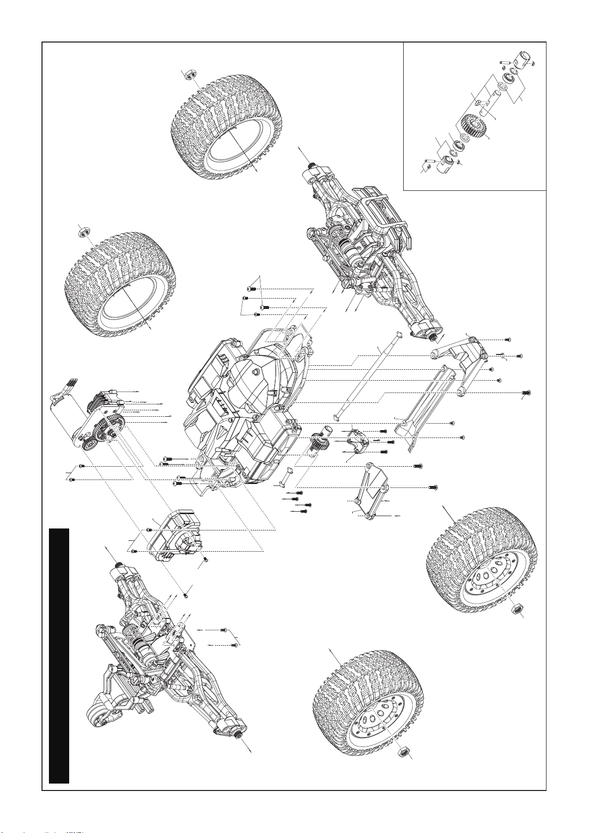
PD10-0048
PD05-0032
PD10-0048
PD1036
Output Driveshaft Assembly
PD7441
PD05-0025
r
r
PD05-0026
PD9010
o
PD1035
o
l
l
l
o
PD05-0033
PD09-0080
l
PD0669
PD9010
PD02-0030
n
n
PD09-0079
o
o
s
l
l
l
k
k
l
s
PD1036
k
k
PD9010
PD02-0031
m
m
m
PD9010
m
PD0669
PD05-0034
o
k
k
k
k
q
q
PD0976
PD09-0079
PD0676
PD10-0047
PD02-0025
PD0676
PD05-0037
PD0678
PD9010
PD9010
COMPLETE CAR ASSEMBLY
PD0666
m
m
n
n
PD0678
p
p
PD10-0048
PD10-0048
Specifications on this page are subject to change without notice. In no event will Thunder Tiger be held responsible for typographical or other errors.
29
Page 31

e-MTA TRUCK SPARE PARTS LIST 零件表
PD01-0013
MOTOR MOUNT
馬達固定座
PD02-0026
PINION GEAR (25T)
馬達齒, 25T
PD02-0031
SPUR GEAR COVER
主齒護蓋
PD02-0022
SPUR GEAR HUB
主齒輪固定座
PD02-0027
SPUR GEAR (55T)
主齒輪, 55T
PD03-0023
PUSH ROD SET
避震器搖臂拉桿組
PD02-0023
DIFF CASE
差速箱外殼組
PD02-0028
SPUR GEAR (51T)
主齒輪, 51T
PD03-0024
UPPR SUSP PLATE
上擺臂補強板
PD02-0024
BEVEL GEAR SET
傘齒輪
PD02-0029
SPUR GEAR MOUNT
主齒輪補強座
PD03-0025
LWR SUSP PLATE
下擺臂補強板
PD02-0025
IDLR / OUTPUT GEAR
齒輪
PD02-0030
CNTR TRANS CASE
主齒輪箱
PD04-0005
SHOCK ROD END
避震器拉桿頭
PD05-0025
CTR DRV OUTPUT CUPS
中央傳動軸套
PD05-0030
MAIN SHAFT
主軸
PD05-0036
SHOCK BUSHINGS
避震器上套筒
PD05-0026
OUTPUT CUP PINS
傳動軸插銷組
PD05-0031
IDLER GEAR SHAFT
惰輪軸
PD05-0037
DRIVE SHAFT SHIMS
軸環
(10) (10)
PD05-0027
TRANS PIN, 2.5x10
軸承銷, 2.5x10
PD05-0032
OUTPUT SHAFT
齒輪箱出力軸
PD06-0012
BELL CRANK
轉向搖臂組
PD05-0028
TRANS PIN, 2.5x16
軸承銷, 2.5x16
PD05-0033
FR DRIVE SHAFT
前中央傳動軸
PD06-0013
BLLCRNK PST & BSHNG
轉向柱&塑膠軸承
PD05-0029
ROCKER ARM POST
避震器搖臂軸
PD05-0034
RR DRIVE SHAFT
後中央傳動軸
PD06-0014
SERVO MOUNT
伺服機座
30
Page 32

e-MTA TRUCK SPARE PARTS LIST 零件表
PD07-0013
SHOCK DIAPHRAGM
避震器空氣活門
PD07-0025
SHOCK PISTON
避震器活塞組
PD09-0069
RR BULKHEAD
後擺臂座組
PD07-0014
SHOCK SHAFT
避震器軸組
PD07-0037
SHOCK EYELET
避震器球頭拉桿
PD09-0070
FR SHOCK TOWER
前避震器支架
PD07-0017
SHOCK PLASTIC PARTS
避震器塑膠配件
PD07-0055
FR SHOCK SPRINGS
前避震器彈簧
PD09-0071
RR SHOCK TOWER
後避震器支架
PD07-0020
SHOCK BODY
避震器套筒
PD07-0056
RR SHOCK SPRINGS
後避震器彈簧
PD09-0072
FR ROCKER ARM
前避震器搖臂
PD07-0024
O-RING & SPACERS
避震器O型環&內環柱組
PD09-0068
FR BULKHEAD
前擺臂座組
PD09-0073
RR ROCKER ARM
後避震器搖臂
PD09-0074
FR BUMPER SET
前防撞板組
PD09-0079
CHASSIS BRACE SET
前/後補強支架
PD09-0084
COVER LOCKS
電池蓋扣件
PD09-0075
RR BUMPER SET
後防撞板組
PD09-0080
TRANS COVER
傳動軸護蓋
PD09-0090
Rx COMPARTMENT
接收機蓋/伺服機蓋
PD09-0076
FRONT SKID PLATE
前差速箱補強板
PD09-0081
WHEELIE BAR SET
第五輪組
PD09-0091
ESC COMPARTMENT
速控器盒
31
PD09-0077
REAR SKID PLATE
後差速箱補強板
PD09-0082
BATTERY ADJ. CLIPS
電池調整夾
PD0976
E-CLIP
E型扣環(2mm)
PD09-0078
MAIN CHASSIS ASSEMBLY
車底盤組
PD09-0083
BATTERY COMARTMENT DOORS
左/右電池蓋
PD0980
SPRING WASHER (20)
彈力墊片 (20)
Page 33

e-MTA TRUCK SPARE PARTS LIST 零件表
PD10-0047
OUTPUT GEAR TENONS
3x3x8雙頭圓鍵
PD1497
SUSPENSION HINGE PIN SET
擺臂固定銷
PD1505
RR TURNBUCKLE
後輪座固定拉桿
PD10-0048
WHEEL HEXS
輪鼓轉換器六角螺帽
PD1498
KNUCKLE / HUB
轉向座組
PD1517
BODY MOUNTS & POSTS
車殼支柱&固定板
PD1465
F / R DRIVE INPUT CUP
中央傳動軸套組
PD1499
ADJUST BALL
擺臂球頭
PD1525
SERVO SAVER
伺服機緩衝組
PD1481
DIFF SHAFT / PINION
傳動小斜齒輪
PD1503
FR TURNBUCKLE
前轉向拉桿
(20)
PD1557
BODY MOUNTS SCREW
車殼支柱固定螺絲
PD1482-1
DIFF SET
差速器組
PD1504
F / R TURNBUCKLE END
前/後球頭連桿組
PD1571
BALL BEARING
軸承組
PD1572
BALL BEARING (2), 6x12x4
滾珠軸承 (2), 6x12x4
PD1745
UPPER SUSPENSION ARMS
上擺臂組
PD1969
BEARING (4), d10xD19xW5
滾珠軸承 (4), d10xD19xW5
PD1577
ALXE BEARING SAPCER
輪軸軸環組
PD1746
LOWER SUSPENSION ARMS
下擺臂組
PD1983
ANENNA BAG
天線管
(20)
PD1600
LOCK WASHER (20), 3mm
防鬆墊片 (20), 3mm
PD1749
DIFFRENTIAL OUTDRIVES & GASKETS
傳動軸套&墊片
(20)
PD2433
LOCK NUT WITH FLANGE
尼龍墊圈螺帽, M5
(20)
PD1709
WASHER (20), 3mm
墊片 (20), 3mm
(10)
PD1896
DIFFRENTIAL SHIME
差速器墊片
PD6341-1
DIFFRENTIAL GEARS
差速器齒輪組
PD1740
DRIVE CUP SET SCREW
驅動軸套固定螺栓
PD1968
B.BEARING (4), d5xD10xW4
滾珠軸承 (4), d5xD10xW4
PD6342
DIFFRENTIAL HOUSING
差速器外殼
32
Page 34

e-MTA TRUCK SPARE PARTS LIST 零件表
PD6343
DIFF SPUR
差速器傳動斜齒輪
PD7237
UNIVERSAL REBUILD KIT
萬向接合套件
PD8322
BEAD LOCK RING (G)
輪轂裝飾片組 (綠)
PD7216
SLIPPER HARDWARE
滑動套件
PD7240
TIRES
輪胎
PD8322-Y
BEAD LOCK RING (Y)
輪轂裝飾片組 (黃)
PD7218
SLIPPER FRICTION RING
摩擦片
PD7441
BEARING (4), d8xD14xW4
滾珠軸承 (4), d8xD14xW4
PD8323
BEAD LOCK RING (O)
輪轂裝飾片組 (橙)
PD7219
SLIPPER LINGING PAD
限滑來令片
(10)
PD7786
DIFF SHIME
差速器墊片
PD8324
WHEEL HEX DRIVE
六角輪轂轉換器
PD7220
SLIPPER HUB
限滑固定座
PD8321
BEAD LOCK WHEELS
輪轂
PD8325
BALL TYPE UNIVERSAL
萬向傳動軸
PD0971 M3 (20)
PD1680 M4 (20)
LOCK NUT
止鬆螺帽
PD9130
BEARING (4), 5x8x2.5mm
滾珠軸承 (4), 5x8x2.5mm
PD7475 M3x10 (20)
SOCKET SCREW
內六角螺絲
PD9186 M3x8 (20)
BHPS SCREW W/WASHER
圓頭十字墊圈螺絲
PD9318
BALL BEARING (2), d5xd13
滾珠軸承 (2), d5xd13
PD0676 M3x6 (20)
PD0677 M3x8 (20)
PD0678 M3x10 (20)
PD0680 M3x14 (20)
PD0681 M3x16 (20)
FHCS SCREW
平頭內六角螺絲
e-MTA TRUCK SPARE PARTS LIST 零件表
PD01-0013 MOTOR MOUNT 馬達固定座
PD02-0022 SPUR GEAR HUB 主齒輪固定座
PD02-0023 DIFF CASE 差速箱外殼組
PD02-0024 BEVEL GEAR SET 傘齒輪
PD02-0025 IDLR/OUTPUT GEAR 齒輪
PD9320
HOLLOW BALLS
拉桿球頭組
PD1598 M4x4 (20)
PD1961 M3x12 (20)
PD1962 M3x4 (20)
SET SCREW
無頭內六角螺絲
(10)
PD9321
CNTR TRANS GASKETS
BT P.M. SCREW
圓頭十字螺絲
PD7471 M2.5x6 (20)
中央齒輪箱墊片
PD0666 M3x6 (20)
PD0669 M3x12 (20)
PD0670 M3x14 (20)
PD0671 M3x16 (20)
PD0672 M3x18 (20)
PD1035 M3x10 (20)
PD1036 M3x8 (20)
PD9010 M4x14 (20)
PD9316 M4x12 (20)
PD9317 M4x35 (20)
PD9319 M4x16 (20)
BHCS SCREW
半圓頭內六角螺絲
PD02-0026 PINION GEAR (25T) 馬達齒, 25T
PD02-0027 SPUR GEAR (55T) 主齒輪, 55T
PD02-0028 SPUR GEAR (51T) 主齒輪, 51T
PD02-0029 SPUR GEAR MOUNT 主齒輪補強座
PD02-0030 CNTR TRANS CASE 主齒輪箱
33
Page 35

e-MTA TRUCK SPARE PARTS LIST 零件表
PD02-0031 SPUR GEAR COVER 主齒護蓋
PD03-0023 PUSH ROD SET 避震器搖臂拉桿組
PD03-0024 UPPR SUSP PLATE 上擺臂補強板
PD03-0025 LWR SUSP PLATE 下擺臂補強板
PD04-0005 SHOCK ROD END 避震器拉桿頭
PD05-0025 CTR DRV OUTPUT CUPS 中央傳動軸套
PD05-0026 OUTPUT CUP PINS 傳動軸插銷組
PD05-0027 TRANS PIN, 2.5x10 軸承銷, 2.5x10
PD05-0028 TRANS PIN, 2.5x16 軸承銷, 2.5x16
PD05-0029 ROCKER ARM POST 避震器搖臂軸
PD05-0030 MAIN SHAFT 主軸
PD05-0031 IDLER GEAR SHAFT 惰輪軸
PD05-0032 OUTPUT SHAFT 齒輪箱出力軸
PD05-0033 FR DRIVE SHAFT 前中央傳動軸
PD05-0034 RR DRIVE SHAFT 後中央傳動軸
PD05-0036 SHOCK BUSHINGS 避震器上套筒
PD05-0037 DRIVE SHAFT SHIMS 軸環
PD06-0012 BELL CRANK 轉向搖臂組
PD06-0013 BLLCRNK PST & BSHNG 轉向柱&塑膠軸承
PD06-0014 SERVO MOUNT 伺服機座
PD0666 BHCS SCREW (20), M3x6
PD0669 BHCS SCREW (20), M3x12
PD0670 BHCS SCREW (20), M3x14
PD0671 BHCS SCREW (20), M3x16
PD0672 BHCS SCREW (20), M3x18
PD0676 FHCS SCREW (20), M3x6 平頭內六角螺絲 (20), M3x6
PD0677 FHCS SCREW (20), M3x8 平頭內六角螺絲 (20), M3x8
PD0678 FHCS SCREW (20), M3x10 平頭內六角螺絲 (20), M3x10
PD0680 FHCS SCREW (20), M3x14 平頭內六角螺絲 (20), M3x14
PD0681 FHCS SCREW (20), M3x16 平頭內六角螺絲 (20), M3x16
PD07-0013 SHOCK DIAPHRAGM 避震器空氣活門
PD07-0014 SHOCK SHAFT 避震器軸組
PD07-0017 SHOCK PLASTIC PARTS 避震器塑膠配件
PD07-0020 SHOCK BODY 避震器套筒
PD07-0024 O-RING & SPACERS 避震器O型環&內環柱組
PD07-0025 SHOCK PISTON 避震器活塞組
PD07-0037 SHOCK EYELET 避震器球頭拉桿
PD07-0055 FR SHOCK SPRINGS 前避震器彈簧
PD07-0056 RR SHOCK SPRINGS 後避震器彈簧
PD09-0068 FR BULKHEAD 前擺臂座組
PD09-0069 RR BULKHEAD 後擺臂座組
PD09-0070 FR SHOCK TOWER 前避震器支架
PD09-0071 RR SHOCK TOWER 後避震器支架
PD09-0072 FR ROCKER ARM 前避震器搖臂
PD09-0073 RR ROCKER ARM 後避震器搖臂
PD09-0074 FR BUMPER SET 前防撞板組
PD09-0075 RR BUMPER SET 後防撞板組
PD09-0076 FRONT SKID PLATE 前差速箱補強板
PD09-0077 REAR SKID PLATE 後差速箱補強板
PD09-0078 MAIN CHASSIS ASSEMBLY 車底盤組
PD09-0079 CHASSIS BRACE SET 前/後補強支架
PD09-0080 TRANS COVER 傳動軸護蓋
PD09-0081 WHEELIE BAR SET 第五輪組
PD09-0082 BATTERY ADJ. CLIPS 電池調整夾
PD09-0083
PD09-0084 COVER LOCKS 電池蓋扣件
PD09-0090 Rx COMPARTMENT 接收機蓋/伺服機蓋
PD09-0091 ESC COMPARTMENT 速控器盒
PD0971 LOCK NUT (20), M3 止鬆螺帽 (20), M3
PD0976 E-CLIP E型扣環, 2mm
PD0980 SPRING WASHER (20) 彈力墊片 (20)
PD10-0047 OUTPUT GEAR TENONS 3x3x8雙頭圓鍵
BATTERY COMARTMENT DOORS
半圓頭內六角螺絲 (20), M3x6
半圓頭內六角螺絲 (20), M3x12
半圓頭內六角螺絲 (20), M3x14
半圓頭內六角螺絲 (20), M3x16
半圓頭內六角螺絲 (20), M3x18
左/右電池蓋
PD10-0048 WHEEL HEXS 輪鼓轉換器六角螺帽
PD1035 BHCS SCREW (20), M3x10
PD1036 BHCS SCREW (20), M3x8
PD1465 F/R DRIVE INPUT CUP 中央傳動軸套組
PD1481 DIFF SHAFT / PINION 傳動小斜齒輪
PD1482-1 DIFF SET 差速器組
PD1497 SUSPENSION HINGE PIN SET 擺臂固定銷
PD1498 KNUCKLE / HUB 轉向座組
PD1499 ADJUST BALL 擺臂球頭
PD1503 FR TURNBUCKLE 前轉向拉桿
PD1504 F / R TURNBUCKLE END 前/後球頭連桿組
PD1505 RR TURNBUCKLE 後輪座固定拉桿
PD1517 BODY MOUNTS & POSTS 車殼支柱&固定板
PD1525 SERVO SAVER 伺服機緩衝組
PD1557 BODY MOUNTS SCREW 車殼支柱固定螺絲
PD1571 BALL BEARING 軸承組
PD1572 BALL BEARING (2), 6x12x4 滾珠軸承 (2), 6x12x4
PD1577 AXLE BEARING SAPCER 輪軸軸環組
PD1598 SET SCREW (20), M4x4 無頭內六角螺絲 (20), M4x4
PD1600 LOCK WASHER (20), 3mm 防鬆墊片 (20), 3mm
PD1680 LOCK NUT (20), M4 止鬆螺帽 (20), M4
PD1709 WASHER (20), 3mm 墊片 (20), 3mm
PD1740 DRIVE CUP SET SCREW 驅動軸套固定螺栓
PD1745 UPPER SUSPENSION ARMS 上擺臂組
PD1746 LOWER SUSPENSION ARMS 下擺臂組
PD1749
PD1896 DIFFRENTIAL SHIME 差速器墊片
PD1961 SET SCREW (20), M3x12 無頭內六角螺絲 (20), M3x12
PD1962 SET SCREW (20), M3x4 無頭內六角螺絲 (20), M3x4
PD1968 B.BEARING (4), d5xD10xW4 滾珠軸承 (4), d5xD10xW4
PD1969 BEARING (4), d10xD19xW5 滾珠軸承 (4), d10xD19xW5
PD1983 ANENNA BAG 天線管
PD2433 LOCK NUT WITH FLANGE 尼龍墊圈螺帽, M5
PD6341-1 DIFFRENTIAL GEARS 差速器齒輪組
PD6342 DIFFRENTIAL HOUSING 差速器外殼
PD6343 DIFF SPUR 差速器傳動斜齒輪
PD7216 SLIPPER HARDWARE 滑動套件
PD7218 SLIPPER FRICTION RING 摩擦片
PD7219 SLIPPER LINGING PAD 限滑來令片
PD7220 SLIPPER HUB 限滑固定座
PD7237 UNIVERSAL REBUILD KIT 萬向接合套件
PD7240 TIRES 輪胎
PD7441 BEARING (4), d8xD14xW4 滾珠軸承 (4), d8xD14xW4
PD7471 BT P.M. SCREW (20), M2.5x6 圓頭十字螺絲 (20), M2.5x6
PD7475 SOCKET SCREW (20), M3x10 內六角螺絲 (20), M3x10
PD7786 DIFF SHIME 差速器墊片
PD8321 BEAD LOCK WHEELS 輪轂
PD8322 BEAD LOCK RING (G) 輪轂裝飾片組 (綠)
PD8322-Y BEAD LOCK RING (Y) 輪轂裝飾片組 (黃)
PD8323 BEAD LOCK RING (O) 輪轂裝飾片組 (橙)
PD8324 WHEEL HEX DRIVE 六角輪轂轉換器
PD8325 BALL TYPE UNIVERSAL 萬向傳動軸
PD9010 BHCS SCREW (20), M3x14
PD9130 BEARING (4), 5x8x2.5mm 滾珠軸承 (4), 5x8x2.5mm
PD9186
PD9316 BHCS SCREW (20), M4x20
PD9317 BHCS SCREW (20), M4x35
PD9318 BALL BEARING (2), d5xd13 滾珠軸承 (2), d5xd13
PD9319 BHCS SCREW (20), M4x16
PD9320 HOLLOW BALLS 拉桿球頭組
PD9321 CNTR TRANS GASKETS 中央齒輪箱墊片
DIFFRENTIAL OUTDRIVES & GASKETS
BHPS SCREW W/WASHER (20), M3x8 圓頭十字墊圈螺絲 (20), M3x8
半圓頭內六角螺絲 (20), M3x10
半圓頭內六角螺絲 (20), M3x8
傳動軸套&墊片
半圓頭內六角螺絲 (20), M3x14
半圓頭內六角螺絲 (20), M4x20
半圓頭內六角螺絲 (20), M4x35
半圓頭內六角螺絲 (20), M4x16
34
Page 36

e-MTA TRUCK OPTIONAL PARTS LIST 選購零件表
PD06-0015
OPTIONAL STEERING SET
轉向搖臂組
PD09-0088
RR ALUMINUM ROCKER ARM
後避震器搖臂
PD1756
STEERING LINK ROD-TI
鈦合金前轉向拉桿
PD07-0021
ALUMINUM SHOCK BODY
避震器套筒
PD09-0092
ALUM SHOCK TOWER, FRONT
鋁合金前避震器支架
PD1757
REAR LINK ROD-TI
鈦合金後輪座拉桿
PD07-0023
ALUMINUM SHOCK CAP
避震器上蓋
PD09-0093
ALUM SHOCK TOWER, REAR
鋁合金後避震器支架
PD07-0027
16mm SHOCK COLLARS
避震器調整環
PD1582
SERVO SAVER, HITECH
轉向伺服機臂
PD09-0087
FR ALUMINUM ROCKER ARM
前避震器搖臂
PD1583
STEERING SERVO SAVER, JR
JR轉向伺服機臂
e-MTA TRUCK OPTIONAL PARTS LIST 選購零件表
PD06-0015 OPTIONAL STEERING SET 轉向搖臂組
PD07-0021 ALUMINUM SHOCK BODY 避震器套筒
PD07-0023 ALUMINUM SHOCK CAP 避震器上蓋
PD07-0027 16mm SHOCK COLLARS 避震器調整環
PD09-0087 FR ALUMINUM ROCKER ARM 前避震器搖臂
PD09-0088 RR ALUMINUM ROCKER ARM 後避震器搖臂
PD09-0092 ALUM SHOCK TOWER, FRONT 鋁合金前避震器支架
PD09-0093 ALUM SHOCK TOWER, REAR 鋁合金後避震器支架
PD1582 SERVO SAVER, HITECH 轉向伺服機臂
PD1583 STEERING SERVO SAVER, JR JR轉向伺服機臂
PD1756 STEERING LINK ROD-TI 鈦合金前轉向拉桿
PD1757 REAR LINK ROD-TI 鈦合金後輪座拉桿
JD7839
 Loading...