

Page 1
-*
rgu
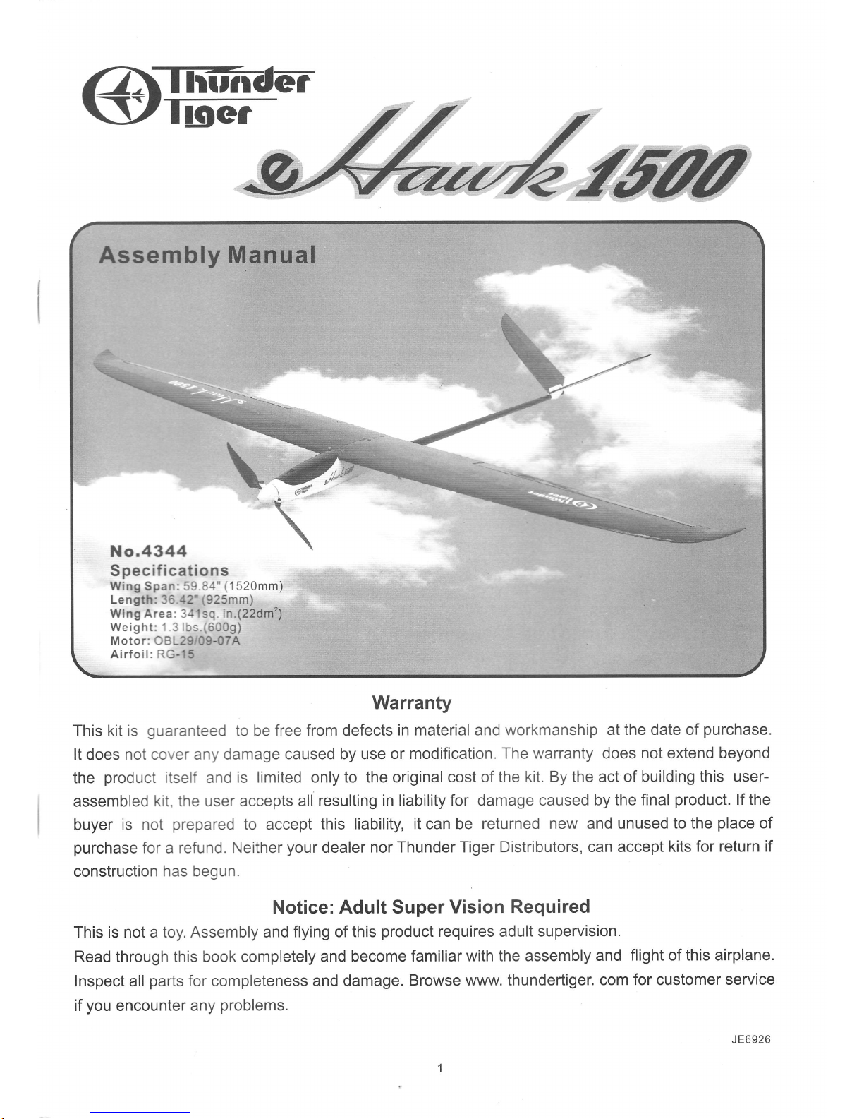
Assembly Manual
Specif
ications
Wing Span: :? 3
j'
'1
520mm)
Length:
ja
:2"
r925mm)
Wing
Area i.:,sr in.(22dm'z)
Weight: - -: o"0gt
Motor: :3 -29 09-07A
Airfoii:tr.3-15
No.4344
Warranty
This
kit is
guaranteed
to be free from defects
in material and
workmanship atthe date of
purchase.
It
does
not co,.'er anyr
damage caused by use
or modification.
The warranty does
not extend beyond
the
product
iisetf
and
is limited only to the original
cost of the
kit. By the act of building
this user-
assembled
kit the user accepts all
resulting in liability
for damage caused
by the final
product.
lf the
buyer
is
not
prepared
to accept
this liability, it can be
returned
new
and
unused to the
place
of
purchase
for a refund.
Neither
your
dealer
nor Thunder Tiger
Distributors, can accept
kits for
return if
construction has begun.
Notice: Adult Super
Vision
Required
This
is not a toy. Assembly and
flying of this
product
requires adult
supervision.
Read through this
book completely and
become familiar
with the assembly
and
flight of this airplane.
Inspect all
parts
for completeness
and damage.
Browse
www. thundertiger.
com
for
customer
service
if
you
encounter
any
problems.
J E6926
Page 2
INTRODUGTION
*g4''u/ffu
Introd
u ctio
n
Thank
you
for
your purchase
of the Thunder Tiger
eHawk 1500 . This new
generation
of a 1 .5M
glider
is
going
to
lift
for those who are
eager
for
the thrill of soaring. Standard
equips efficient outrunner
OBL29/09-
07A and
performance
folding
prop
that make eHawk 1500
an outstanding 1.5M EP
glider
in
the market.
Advanced from its
brother eHawk 1400, the new 1500
combines
proven
RG15
airfoil
plus
convenient
removable
wing halves and V tail
design for easy transportation.
The eHawk 1500 is
designed for intermediate
pilot
minded.
Before
beginning the assembly read the
instructions
thoroughly to
give
an understanding of the sequence
of steps and a
general
awareness of the
recommended
assembly
procedures.
Check the entire contents
of
your
kit against the
parts
drawing and
photos
to make
sure that no
parts
are
missing
or damaged. This will
also help
you
to become familiar
with
each component
of
your plane.
lf
you
find
that any of the
parts
are either missing
or damaged,
please
contact Thunder
Tiger Distributors for
Customer Service.
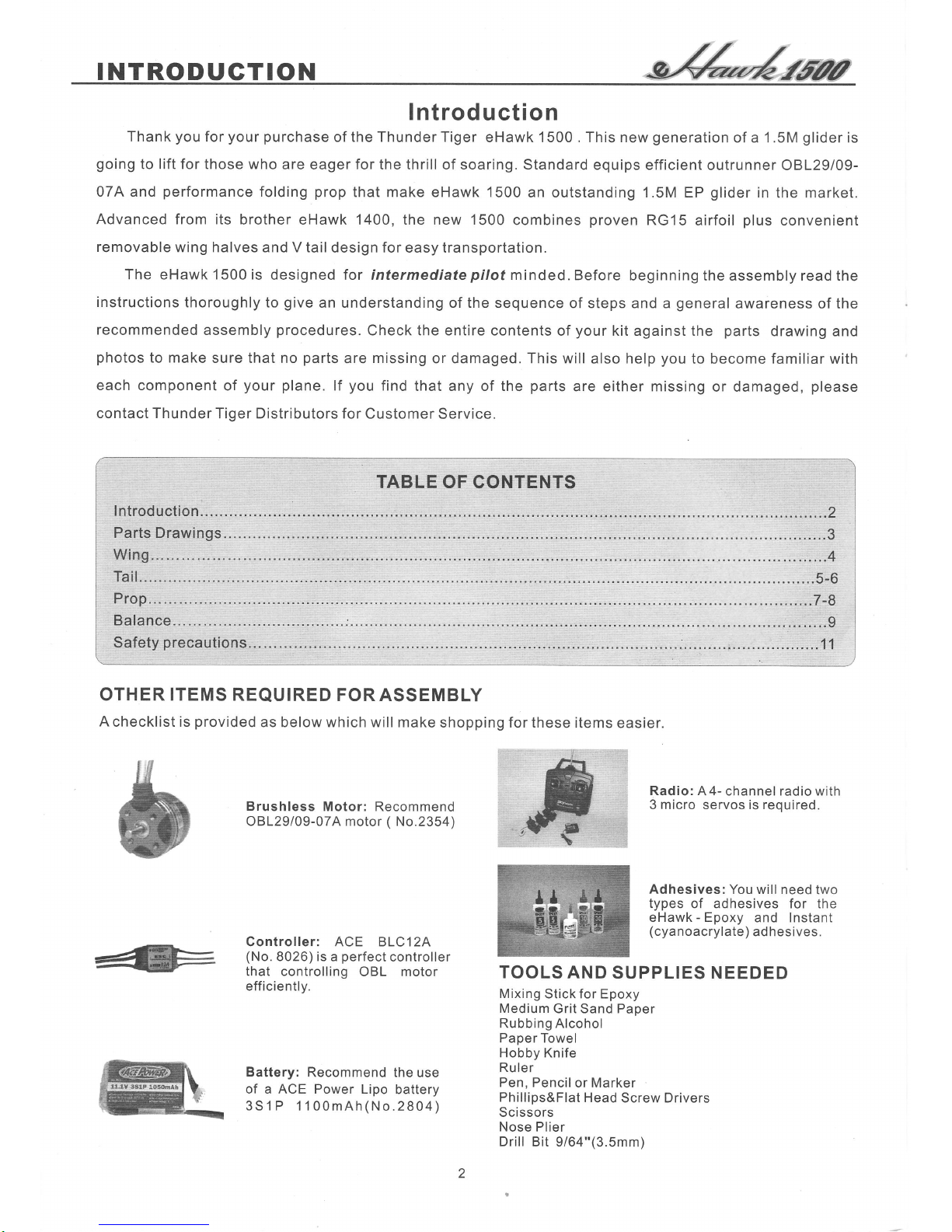
OTHER ITEMS REQUIRED
FOR ASSEMBLY
A
checklist is
provided
as below which will make
shopping for these
items
easier.
Brushless
Motor: Recommend
OBL29/09-074 motor ( No.2354)
Radio: A 4-
channel radio with
3 micro servos is reouired.
Adhesives:
You will need
two
types of adhesives
for the
eHawk - Epoxy
and Instant
(cyanoacrylate)
adhesives.
Gontroller: ACE BLC12A
(No.
8026) is a
perfect
controller
that controlling
OBL motor
efficientlv.
Battery:
Recommend the
use
of a ACE Power Lipo
battery
3Sl P'1100mAh(No.2804)
TOOLS AND
SUPPLIES NEEDED
Mixing
Stick for Epoxy
Medium
Grit Sand Paoer
Rubbing Alcohol
Paoer Towel
Hobby Knife
Ruler
Pen, Pencil
or Marker
Phillios&Flat
Head
Screw Drivers
Scissors
Nose Plier
Drill Bit
9/64"(3.5mm)
Page 3
lTiffiundm
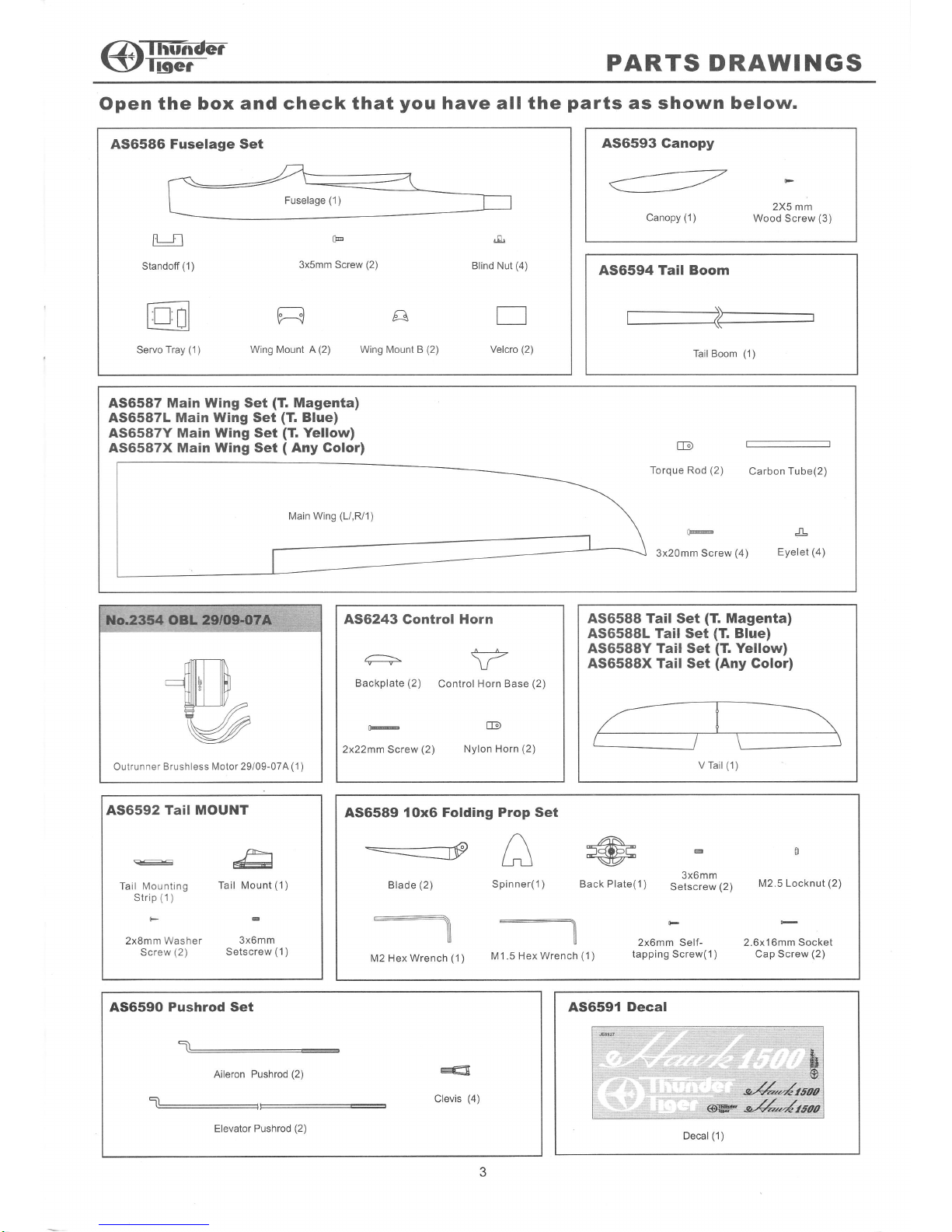
PARTS DRAWINGS
Open the
box and check that
you
have all the
parts
as shown below.
A36586 Fuselage Set
Standoff
(1
)
l't I nl
t'L--l't tl
i-l
Servo Tray
(1
)
@
3x5mm Screw
(2)
t2-J
A
Wing Mount A
(2)
Wing Mount B
(2)
,-E
Blind Nut
(4)
r
Velcro
(2)
A56594
Tail Boom
Tail Boom
(1)
2X5 mm
Wood Screw
(3)
A56593
Ganopy
:
Canopy
(1
)
A56587 Main Wing Set
(T.
Magenta)
AS6587L Main
Wing
Set
(T.
Blue)
AS6587Y Main
Wing
Set
(T.
Yellow)
AS6587X Main Wing Set
(
Any Golor)
Torque
Rod
(2)
Carbon
Tube(2)
Main Wing
(L/,R/1)
A56243
Gontrol
Horn
';------
Backplate
(2)
Con
2x22mm
Screw
(2)
\r
trol Horn Bas
@
Nylon Horn
(2)
e
(2)
Outrunner
Brushless Motor 29l09-07A
(1
)
A56592
Tail MOUNT
R-€
Tail
Mounting
T
Strip
(1)
F
2x8mm Washer
Screw
(2)
G
#
ail Mount
(1)
3x6mm
Setscrew
(1
)
A56588 Tail
Set
(T.
Magenta)
AS6588L Tail Set
(T.
Blue)
AS6588Y
Tail Set
(T.
Yellow)
AS6588X Tail Set
(Any
Golor)
AS6591
Decal
Decal
(1
)
A56589 {OxG
Folding Prop Set
-=.__---xp
/_\
Lfu
M1.5 Hex Wrench
(1)
@
ack
Plate(1
)
oS
3x6mm
Setscrew
(2)
M2 5 Locknut
(2)
F
2x6mm Self- 2.6x16mm Sockel
tapping Screw(1) Cap Screw
(2)
:
M2 Hex
Wrench
(1)
AS6590 Pushrod Set
5_
Aileron
Pushrod
(2)
Elevator Pushrod
(2)
Clevis
(4)
?
Page 4
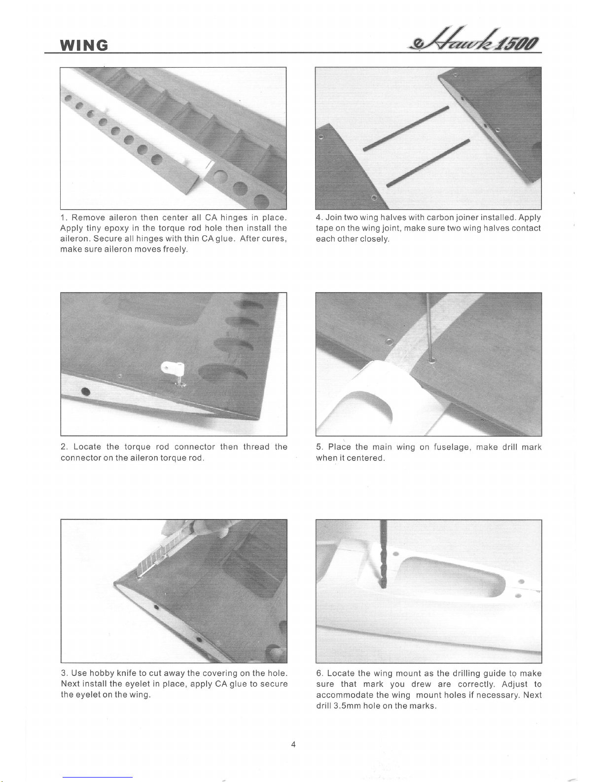
1. Remove
aileron
then
center
all CA hinges in
place.
Apply
tiny epoxy
in the torque rod hole then install the
aileron. Secure all
hinges with
thin CA
glue.
After
cures,
make sure aileron moves freelv.
2. Locate the torque rod
connector then thread the
connector on the aileron torque rod.
3. Use hobby knife to cut
away
the
covering on the
hole.
Next install the eyelet in
place,
apply CA
glue
to secure
the eyelet on the wing.
4.
Join
two wing halves with
carbon
joiner
installed. Apply
tape
on the
wing
joint,
make sure two
wing
halves contact
each other closelv.
5. Place the main
when it
centered.
wing
on
fuselage,
make drill mark
6. Locate the wing mount as the drilling
guide
tg make
sure that mark
you
drew are correctly. Adjust to
accommodate the wing mount holes if necessary. Next
drill
3.5mm hole
on the
marks.
Page 5

@lPr..-
TAIL
rt
.1
,,.
r.
.i
gl
',s{
'E
G
a_ ts
I'f:l
brd
:ffi
'
t..
7.
Installthe
blind nut on the wing mounts
as shown.
8. Glue
wing
mounts in
place.
You may need to sand the
glue
area to enhance the
adhesion.
Make
sure there is
no
glue
in the blind nut.
i.irf
I
il
I
"
1"
.l
10. Secure the
servo
with the
grommet,
eyelets and wood
screws
which
come
with
the servo as
photo
shown. Note
the orientation of the servos.
a
j
11.
Glue the servo tray in
fuselage.
Note: do not
push
in
too much as it might brake the fiberglass. Recommend
the servo tray edge is 1-112"
(40mm)
to the fuselage
wing leading edge.
12. Locate
and
install
elevator control
horn then thread
the connector as shown.
9. Glue the servo
standoff on
the
servo tray as shown.
Page 6

TAI L
I
13.
Cut away the mounting
hole covering with hobby knife.
lron
the center mounting
area if necessary.
14. Locate the
tail boom and
the tail mount.
Secure the
tail mount in
olace
with
3x6mm set screw as shown.
Note that the
pushrod
exit holes are
level with the mount
16. Thread the
clevis on the
pushrod,
note the
orientation
of Z-bend
end and clevis.
17. Insert
the Z-bend
end of the
pushrod
to the exit hole as
shown. Do not
snap on the clevis
at this moment.
18. Locate
the
servo
horn,
insert the Z-bend
end at the
second hole. Trim
away the excess
portion
of the servo
horn
as
it
will contact
the fuselage.
15. Bend
the horizontal tail
then
next
secure the tail on the
tail
and 2X8mm washer screws.
olace
the tail
on the
mount
mount with mounting
strip
Page 7

@ffiF
PROP
t)t
19. Attach the tail
boom then reach two
pushrods
on the
servo.
Make
sure the
oushrod
should
be cross to each
other.
That
is to say the left elevator
servo controls the
right elevator. Secure the
servo
horn with
servo screw
when servo is in neutral
oosition.
20. Temporally install main wing on fuselage with four
3x20mm screws. Adjust the tail boom make sure V tail is
at
the same angle to the main wing next
glue
the tail
boom in
place.
22. Remove the main wing, install
the aileron servo horn
and
pushrod.
Thread
the clevis on the
pushrod.
23. Install the main wing again, adjust the
clevis and snap
it onto the control horn when
servo is in neutral oosition.
24. Secure the
motor ( recommend Thunder Tiger
OBL29/09-07A)
with 3x5mm screw. Make
sure
the wires
do not contact to the motor can. Tape the wires if
necessary.Locate the Folding Prop
accessories as shown.
21. Adjust the clevis and snap on the elevator control horn.
Page 8

PROP
-sZL-r{6aa
1
*l
f"\"
25. Install
the blade
holder
on
the motor with two 3x6mm
set
screws.
Make sure the holder does not contact the
screw but as close as oossible to the fuselace.
26. Install the folding
prop
with the 2.6x16mm
socket
screws
and
M2.6 locknut. Do not
over
tighten the
screw
make
sure
it
can
fold
back
freelv.
28. Locate Velcro
and cut
it into
two oieces.
Attach
the
Velcro to
battery
pack
and attach the other
halves
of
Velcro to the fuselage. Refer to manufacturer's Receiver
and ESC manual then connect all connectors
properly
and setup V-tail function. The ESC and RX are located
as snown.
,
--ti
29. Thread the antenna through the
aileron exit
hole
then
tape it on the boom
to the tail.
27. Installthe
spinner with 2xOmm self-tapping screw
as snown.
30. Trim the canopy
alone
with the molded line.
Cut away
the
air
inlet for
cooling
?
/
.,:',1
''iil
'
''
t;!'
'
*..,i
.\
t
Q
Page 9

@lP,"..-
BALANGE
31. Position the canopy in
place.
You may
use tape
the canopy in
place.
Or
you
may drill three 1/16"
(
holes then secure the canopy with furnished
wooo screws.
IMPORTANT-Do not fly
your
model
before completing
this
very important
section. A model that is not
properly
balanced will
be
unstable could cause
serious damage and/or injury.
1.Turn the wing(and
plane
if assembled) up
side down
and measure about 2-1l8"(53mm)from
the
Leading
Edge
of the wing root then make a mark with
your
felt-tip
pen.
This is the
balance
point.
2.With
your
model
fully assembled turn the model upright
and
pick
it
up
with
one
finger
at each of the balance marks
you
made
earlier. lf balanced
properly
the
plane
will
hang horizontally.
2-118"(53mm)
Pick
up
model
at arrows.
Balancing
your
model is very important and must not
be
overlooked. The
center of
gravity
(CG)
is
2-118"
behind
the leading edge of the wing near
the wing
root,
parallel
with
the fuselage. You can adjust the battery
pack
forward
or backward to
reach the riqht
CG.
FIRST FLGHTS
to tape
1.5mm)
2x5mm
Make sure the direction of servo moves
correctly.
lf
not,
switch
the
reversing switch on the transmitter. Adjust
the
control
throws as
following
suggested.
__---r3t8"'vnn
{,^".u,n-
5/8".l5mm
Before
you
attempt to
some final checks:
1 . Fully charge
your
the manufactures
fly
your
model
you
should
perform
radio and flight
batteries
following
instructions.
114",6nm
l/4",6mm
2.Check the direction of travel of
your
control surfaces
and the ooeration
of
the motor
controller oer the
manufacturers instructions.
3.Range check
your
radio
system
per
the
manufactu rers i nstructions.
4.Double
check
that
you
have installed the screws in
the servo control arms and that the clevises are
snapped tightly on the control horns.
We
strongly
recommend that
you get
help from an
experienced R/C
pilot
if
you
are
just
beginning. You
should be able to
find
help at
your
local
dealer or
club field.
First
of all,
if
you
are flying with other flyers, check to
make
sure
they are not operating on the same frequency
as
you.
lf they
are,
do
not turn on
your
radio until they
have
safely
landed and have turned their radio off.
3/8",9mm
3/8",9mm
Aileron-Low
Rate
Aileron-High Rate
Elevator/Rudder
-Low
Elevator/Rudder
-High
Rate
Page 10

FIRST FLIGHT
Secondly, even though the eHawk
1500 is
very easy
to
fly, if
you
are a novice modeler/pilot, we
highly
recommend that
you
seek the help of an experienced
modeler for
your
first few flights. He can save
you
a
lot
of time and
possible
disappointment by
helping
you get
your
model in the air safely and
getting
it trimmed out
for
you.
lmportant:The radio control system
is
set up to operate
the control surfaces
just
lick a real airplanes as
if the
pilot(you)
are sitting
in cockpit
controlling the airplane.
When
you
want the
plane
to dive,
you push
the elevator
stick forward
(up),
to climb
you pull
the stick back
(down),
to turn
right,
you
move
the aileron
stick
to right
with
elevator up and
vise
versa.
When
you
want to turn
the motor on
you push
the throttle stick forward
and
when
you
want to turn the motor off
you pull
the stick
back.
lt is
the turning
that
causes
the most
problems
with novice
pilots
because when the
plane
is
flying
towards
you
a
right turn
command
on the transmitter
cause the
plane
to turn to
your
left
(which
is
the
planes
right). Get the
picture?
Fortunately the up and down
commands do
not change. The easiest way to conquer
this
problem
is
to
try and
always
face
your
body
near
the direction the
planes
are flying. This means that
you
will
have
to look over
your
shoulder
at times, but many
modelers find this an easy way to learn.
THE
FIRST FLIGHTS
You should
always
use
the
first few flights to
get
accustomed to
your
new airplane and
its flying
characteristics. Keep the model upwind and climb
to a
good
comfortable altitude to cut off
the motor and trim
your
eHawk 1500 for a
glide.
At altitude cut the
motor
and start
your glide.
Have
an
experienced modeler
adjust the trims of the transmitter
for
you
until the
plane
will
glide
straight
and level without any
other
control
input.
Once the trims are set
practice
making smooth
turns in
both directions
while losing as little
altitude
as
possible.
When the eHawk 1500 starts to
get
too
low
for
comfort turn the
motor
back on and
climb
back
uo to
altitude. Practice
this
climbing
and
gliding
until
you
are comfortable with the airplane.
Depending
on
the
battery
you
use
the
eHawk
1500 will
make 5 to
6
good
climbs up to a nice thermal searching
altitude
from
single
battery
charge. Once the
ESC
shuts off the
power
to the motor
you
will need to set up
for
your
landing. Continue to
make
smooth
gently
turns while lining up the
eHawk
1500 with
your
landing
strip. Once
you
are set up to land
keep
the wings
level
and let the model settle in for
an
nice
gentle
landing
while adding up elevator to keep the nose up slightly as
the
plane
slows
down. Make
several
flights like this to
really familiarize
yourself
with
the characteristics of
your
model
and to
learn
the
glide
and distance covering
abilities
of
the eHawk 1500. Once
you
have mastered
a
good
"comfort
level"
you
are
ready to
start searching
for thermals which
will really
increase
your
flight times.
THERMALS
Thermal soaring is one of the most interesting and
challenging types of flying there is. Believe it or
not,
your
eHawk 1
500
is capable
of
flights thousands of feet
high, lasting for
several
hours,
and covering dozens of
miles. The following
paragraphs
will help explain how
to
take advantage
of
natures
energy sources
called
thermals.
"Thermal"
is the term applied to
columns
of rising air.
This air is rising
because
it is warmer
than
the
surrounding air. A dust devil is simply a
thermal
which
ahs
picked
up some dust. Even a tornado is very
similar to a thermal, but of course much stronger.
Thermals occur when
the
sun, or other
heat
source,
heat
the air in one location faster and/or
warmer
than
the surrounding air. Darker surfaces
(plowed
fields,
asphalt
parking
lots, etc.) absorb the sun's energy
faster than lighter
colored and
are
generally good
thermal
generators.
This warmer air
is lighter
(less
dense)
than the
cooler air
and thus rises. The rising air
naturally starts to rotate,
much
like
water
going
down a
drain, and forms
an
inverted funnel shaped
column
that usually
gets
larger
with
altitude.
This
warmer
air
often contains water vapor which condenses as
it
reaches the
cooler air
high
above
the earth forming big
puffy
Cumulus clouds
that
experienced sailplane
flyers
willwatch to determine where the thermals are forming.
Thermals vary in
strength, but often
contain
air
that is
rising at speeds over 1200 feet
per
minute.
Some
thermals are
so strong
they
can even
rip
a sailplane
apart, especially if the
plane
is flying
fast
when
it
passes
through
the
thermal.
THERMAL
SOARING
It takes
lots
of
oractice
and
concentration to thermal
soar
like the
Hawks and Eagles. Since the
pilot
is
not
sitting inside
an
model sailplane, he cannot
feel
the
thermal,
he
can only see
his
sailplane's
reaction
to
the
thermal. Therefore, the majority of the time,
unless
the
pilot
is
paying
careful attention to the
plane,
he
may
not even realize that
plane
is near a thermal. Since
most thermals
are relatively small, less than a hundred
feet in diameter near the
ground,
the sailplane will
rarely
fly
directly into the thermal and
start
rising.
More likely,
it will fly near a thermal and the wing
closest to the
thermal
will rise
turning
the
plane
away
from the thermal. So as
you
can see, an inexperienced
pilot
may
bounce around between
the thermals with
ever
knowing
that he is encountering rising air.
In
order
to
take advantage of thermals,
you
need
to fly
smoothly with
as
few
control
inputs
as
possible.
Watch
the sailplane carefully and it will tell
you
what the air
around it is
doing.
When a sailplane does fly
directly
into a thermal it
will
either start rising
or
stop
sinking at
its
normal
rate.
Either case is reason enough to explore further.
Continue flying straight ahead until
you
have
obviously
passed
through the area
of strongest
lift. Now start
circling
in fairly
tight, but smooth circles. Because
of
the thermals inverted funnel shape, the lower the
planes
altitude, the tighter
the
circles need to be. As
the
plane
gains
altitude, the diameter of
the
circles
can
be increased. lf
you
see the
plane
falling
off
on one
side
of the
turn,
move the
circle over
into the stronger
lift. Thermals
are swept
along
by the
wind
so allow
10
Page 11

ZlTn-ifrdm
\)tf
locr
SAFETY PREGAUTIONS
your
circle
to
drift downwind
with the
thermal. Be
careful when following a thermal downwind though as
you
still
have to be able to make it back to
the field!
lf the sailplane is flying along and all of a sudden turns
by itself, it has
probably
flown near a thermal. Keep in
mind
that thermal
will have
tendency to turn the
plane
away, so
make
a 180 degree turn and fly back towards
the thermal . lf
you
don't
quickly
encounter lift
start
searching around that area. lf
you
find the
thermal,
follow the
procedure
outlined
above to take advantage
of it.
Thermals can be
generated
at any time
of the day, but
the strangest thermals are usually
produced
when the
sun
is
directly overhead 10:00am to 2:00pm
seems to
be the best time to find the strongest thermals.
lf
you
find
yourself getting
too high or
you're
having
trouble
getting
out of a strong thermal. DO
NOT dive
the
plane
to lose
altitude.
This
will very
quickly
over-
stress the airframe and blow the wings
off the
pla
The easiest
and safest
way
to
qulckly
lose
altitude
i
apply full rudder
(either
right
or
left)
and full up
eleva
This will
put
the
plane
into a tight spin that will
normally
not over-stress the airframe. This is
especially useful if
the sailplane
gets
sucked into a cloud
or
gets
too high
to see. The
spinning action
will
give
the
sun a better
chance of reflecting off of the wing
and catching
your
attention.
As
you
might
expect,
with
all this rising
air, there must
also be some sinking
air.
This
sinking air is the
sailplane
pilots
enemy and
one of
the
factors that really
make
eHawk
1500
challenging.
"Sink"
as it is referred
to, is usually not as strong
as
the
nearby thermals, but
is
can
quickly put
a sailplane on the
ground.
Sink in
one
of the reasons,
you
have to be very
careful when
chasing a thermal downwind.
lf
you
encounter sink,
immediately
turn and fly 90 degrees to the
direction of
the wind. Apply a little down elevator to
pick
up some
speed and
get
out of the bad
air as
quickly
as
possible.
You as the
pilot
of this radio
controlled model are
responsible for
any accidents that may
occur during its
use. We recommend
that
you
fly
your
model at a model
club
field
which is specially set up for modelflying.
But
always be sure that
you
operate the model in a
safe and
careful manner and read the
Safety Cautions which
enclosed in the kit
as
following.
Now that
you
have
completed the
assembly of
your
eHawk 1500 model we feel
that have a very
capable
and
good
looklng
2-meter electric
sailplane. We hope
that
you
will enjoy this model
and
get
many hours
of
flying
pleasure
from
its use. Thank
you
for
purchasing
this eHawk 1500 from Thunder
Tiger and we look
forward
to
providing
you
with other
great
RiC
products
in the future.
@ffiF
R/C Model
Airplane
Wffi
THUNDER TIGER CORPORATION
http://www.thunderti
ger.com
@E
€N
11
 Loading...