

Page 1
Page 2
CONTENTS
Electric. Flybarless Edition
INTRO & CAUTION 簡介與注意事項
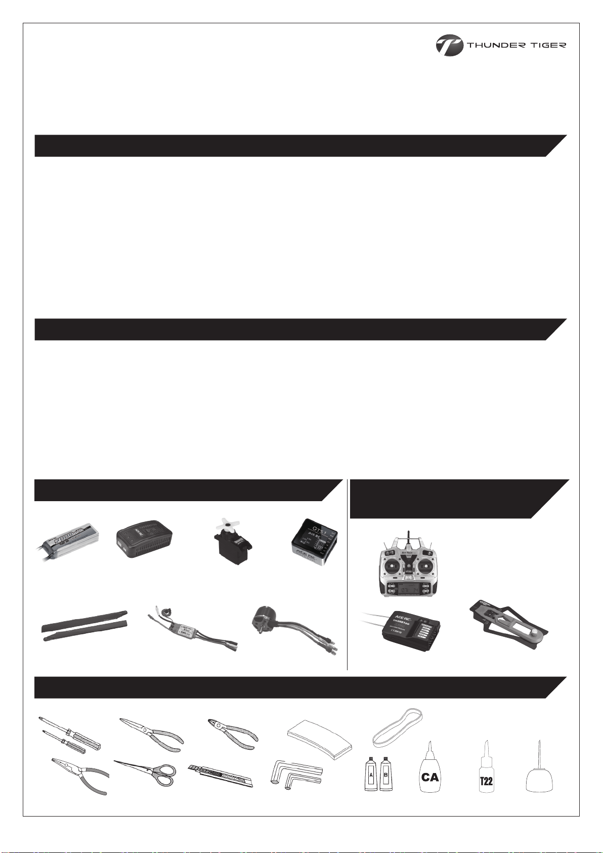
CONTENTS INCLUDED 內容物說明
ADDITIONAL ITEMS REQUIRED 另購配件
TOOLS REQUIRED FOR MAINTENANCE 另購維修工具
SET-UP SECTION 設定程序說明
ASSEMBLY 組裝說明
DEVICE CONNECTION 設備連接說明
GT5.1 GYRO SETTING 三軸陀螺儀設定
MODEL & SWASHPLATE SETTING 模型及十字盤模式設定
SWASHPLATE & SERVO MOVEMENT SETTING 十字盤及伺服機動作設定
LINKAGES AND SERVO NEUTRAL ADJUSTMENT 連桿及伺服機中立點調整
COLLECTIVE PITCH RANGE SETTING 螺距範圍設定
TAIL AND GYRO SETTING 尾舵及陀螺儀設定
ESC SETTING 電子調速器設定
CURVE SETTING 曲線設定
BLADE TRACKING ADJUSTMENT 主旋翼軌跡調整
2
3
3
3
4
4
5
7
7
8
8
9
9
10
11
CAUTIONS OF LI-PO BATTERY PACK USING 鋰聚電池使用注意事項
INSTRUCTION OF LI-PO BATTERY CHARGER 鋰電池充電器使用說明
AFTER FLIGHT CHECKLIST 飛行後的檢查項目
EXPLODED VIEW & SPARE PARTS LIST 爆炸圖檢索 & 維修零件包表格
MAIN ROTOR HEAD 主旋翼頭
MAIN FRAME (SKID & MOTOR) 本體(腳架&馬達)
MAIN GEAR 主齒輪
TAIL UNIT (RUDDER SERVO) 尾部總成(尾舵伺服機)
TAIL BOOM & CYCLIC SERVO 尾管與舵面伺服機
MAIN ROTOR BLADE & CANOPY 主旋翼與機殼罩
-1-
12
12
12
13
15
17
19
21
23
Page 3
INTRODUCTION
Thank you for purchasing the Thunder Tiger R/C helicopter. This new helicopter is the latest innovation by Thunder Tiger. It has the
perfect combination of flying stability and the agility for 3D flying. This helicopter is an excellent choice for flying enthusiasts like you.
For convenient assembly and safe operation of the helicopter, please read the instructions carefully. Retain the user manual in case
you need it for any information or reference.
感謝您購買雷虎科技直昇機產品,本項產品為雷虎科技全新開發機種,兼具高度穩定性與3D飛行特性,是熱衷引擎直昇機的您不可錯過的選擇。請
於使用本產品前詳盡閱讀使用手冊,以利於組裝工作順暢進行與安全操控本產品。請妥善保存使用說明書,以利後續調整與維修參考用途。
簡介
CAUTION
1. R/C models are not toys. This product is a high-precision flying machine. Possibilities of unexpected crashes may occur due to
electronic interference, incorrect operation, or poor mechanical maintenance. Although it is a small-sized helicopter, the rotor blades
rotate at high speeds, which may cause serious damage, injury, or death if the model hits people or property. Therefore, extreme
caution must be exercised during operation.
2. Thunder Tiger ensures parts packaged in this product have the highest quality. However, after assembly and usage, parts damaged
due to wear or misuse will not be replaced under any circumstances. If you have any questions regarding its operation and repair,
Thunder Tiger’s service agents are able to provide free technical guidance.
3. This product is only recommended for users ages 16 and up. Because flying a R/C helicopter is difficult, beginners must receive
guidance and supervision from experienced pilots to minimize unexpected danger. Practice in spacious areas, far away from
obstacles such as buildings, trees, electrical towers, or crowds.
4. To decrease the cost of repair and maintenance for beginners, it is recommended to fly the helicopter with a practice rack and to
learn basic flying skills with a computer R/C flying simulator. (Crashes in simulators are free to repair!)
1. 本項遙控直昇機產品並不是玩具,是一項結構精密、高專業度模型產品,如果未經正確組裝與操控,將可能對操控者或其他人造成身體傷害。使用
者必須了解,若未確實進行飛行前安全檢查或操控不當,而造成人員受傷或物體損壞,使用者必須負起法律責任。
2. 本產品由高品質零組件組成,雷虎科技對於安裝過程、使用過後...等人為因素造成損壞事件不負損壞賠償之責。如您需要本產品相關組裝、調整或
其他協助,可與雷虎科技全省經銷商聯繫。
3. 本項產品禁止十六歲以下青少年與孩童使用。強烈建議初學者應取得技術支援後再進行飛行,以避免危險發生。請於空曠地區操控本產品,並避免
於建築物、樹木、電塔...等障礙物區域飛行。
4. 建議初學者可安裝練習架或透過電腦模擬軟體練習,可達到實際練習效果與符合經濟效益。
AMA INFORMATION
Operating a model helicopter requires a high degree of responsibility and skill. If you are a newcomer to the hobby, it is best to seek
help and guidance from accomplished model helicopter pilots. This will greatly speed up the learning process and make you to fly
successfully in a reasonable amount of time. We also would strongly urge you to join the Academy of Model Aeronautics. The AMA is a
non-profit organization that provides its members with a liability insurance plan as well as monthly magazine entitled Model Aviation. All
AMA charter aircraft clubs require all pilots to hold a current AMA sporting license prior to operation of their models at club fields. For
further information, contact the AMA at:
Academy of Model Aeronautics
5151 East Memorial Drive
Muncie, IN 47302
(317) 287-1256
操控遙控直昇機對於飛行安全要求極高,需要高度的負責任態度配合,以及較高的操控技巧。如果您是一位初學者,建議您必須向當地專業模型經銷
商,或是遙控直昇機相關組織以及經驗豐富的玩家尋求相關協助,以獲得您所需要的訊息以及專業知識。如此可有效協助您縮短學習的時間,更容易
學會遙控直昇機的組裝、設定與操控技巧。
警告
特別注意事項
FLIGHT SAFETY CHECKLIST
1. Make sure that the transmitter battery is fully charged before flying.
2. Make sure all control surfaces are operated properly before flying.
3. Do a range check of the radio before the first flight. The electronic equipment must operate properly at a range of at least 5 meters
(18 ft) even with the transmitter antenna collapsed.
4. Make sure there are no other pilots using the same radio frequency with yours and that there are no other radio interferences on your
frequency.
5.
Be sure to turn on the transmitter first with the throttle stick in the idle position. Plug the battery into the ESC last.
6. The main rotor and the tail rotor spin at very high RPM. Make sure nothing can come in contacting with the rotor blades during flight.
7. Always maintain a safe distance from the helicopter during flight.
8. Never fly the helicopter in the rain or in excessive wind conditions.
9. Always operate and fly the helicopter in a safe and responsible manner.
10. Never fly the helicopter over other pilots, spectators, cars or anything that could result in injury or property damage.
1. 確認接收機與發射機電池,均已確實充電完成。
2. 確認所有操控介面運作順暢。
3. 確認無其他無線電波干擾,且不與其他同好同時使用相同頻率。
4. 確實將油門搖桿放置於低速,再將發射機電源開啟,然後再將電池接上。
飛行前安全確認工作項目
-2-
Page 4
5. 確認遙控器發射器與接收機工作正常,將機體放至於距離5公尺外,確認遙控器是否正常,機體控制動作是否正確。
6. 主旋翼與尾旋翼轉速相當高,運轉時須避免任何障礙物與旋翼接觸。
7. 飛行時,需與遙控直升機保持安全距離。
8. 勿於下雨天或是強風的狀態下操控遙控直升機。
9. 請以安全為第一考量,並以高度負責任的態度參與遙控直升機活動。
10. 禁止於人群、車輛..或任何其他障礙物上方飛行遙控直升機,避免意外發生。
POST FLIGHT INSPECTION
1. Inspect the model thoroughly to ensure no parts have come loose or become damaged during the flight and landing. Replace
damaged parts and tighten loose screws before flying again.
2. Clean the helicopter body.
3. Lubricate all moving parts to ensure smooth operation for the next flying.
4. Replace any worn ball links and damaged bearings.
5. Store the model in a cool, dry place. Avoid putting it under direct sunlight or near a source of heat.
Following these simple rules will allow you to enjoy the thrill of model helicopter flying for many years.
1. 飛行結束後確認機體所有的零件與螺絲是否有損壞或鬆動,更換損壞零件與確實固定鬆動的螺絲。
2. 機體清潔乾淨。
3. 檢查所有活動零組件是否運作順暢,以利下次飛行。
4. 更換所有鬆動的連桿、接頭,以及損壞的軸承。
5. 將機體存放於陰涼通風處,避免機體放置於陽光直射處或接近熱源。
確實執行上述幾項簡單的步驟,將可確保您的愛機維持數年的壽命!
CAUTION
When the model crash occurs, inspect the flybar, rotor shaft and the blade spindle to make sure they are not bent. If any item is
damaged, it must be replaced with a new part to ensure safe operation. Do not glue any broken or damaged plastic parts. Do not
repair broken rotor blades. It is very important to inspect the motor, speed control and the battery.
Always inspect the following items:
Gears, Ball links, Link rods, Bearings, Main shaft, Flybar, Spindle, Tail boom and support, Fins, Tail rotor shaft, Belt, Main blades, Tail
blades, the Motor, the Speed control and the Battery.
機體一旦發生墜落事件,請確實檢查平衡桿、主軸、橫軸是否有彎曲變形,如果有任何的損壞,請立即更換原廠新的零組件,確認機體操作安全!
切勿使用任何接著劑嘗試黏合塑膠零件;請勿使用修復過的主旋翼。馬達、速控器、電池的安全檢查工作亦相當重要。
發生機體墜落事件後,請確實檢查下列項目:
齒輪組、球頭連桿、連桿頭、軸承、主軸、橫軸、尾軸、平衡桿、平衡片、尾管、尾管支撐架、垂直與水平尾翼、尾驅動輪、皮帶、主旋翼、尾旋
翼、馬達、速控器、電池。
注意事項
飛行結束安全檢查事項
CONTENTS INCLUDED
* available depending on the ARF you purchase. 內容物會因購買型號不同而有所差異。
* Li-Po Battery
鋰聚合物電池
325 mm Carbon Blades
碳槳,325 mm
* Balance Charger for
Li-Po Battery
平衡鋰電池充電器
TOOLS REQUIRED FOR MAINTENANCE
Screw Driver
螺絲起子
Needle Nose Pliers
尖嘴鉗
內容物說明
Micro Digital Servo x 4
迷你數位伺服機 x 4
Speed Controller
速控器
Nipper
斜口鉗
3 AXIS Gyro
三軸陀螺儀
Brushless Motor
無刷馬達
另購維修工具
Two-Sided Rubber
雙面膠
ADDITIONAL ITEMS REQUIRED
另購配件
Transmitter
(helicopter type only,
6 or more channels)
發射機(6動以上直昇機用)
Receiver
接收機
Rubber Band
橡皮筋
Pitch Gauge
螺距尺
Ball Link Pliers
連桿專用鉗
Scissors
剪刀
Hobby Knife
模型專用美工刀
Hex Wrench
六角板手
-3-
Epoxy
環氧樹指
CA Glue
快乾膠
Threadlocking
螺絲防鬆膠
Grease
潤滑油
Page 5
ASSEMBLY 組裝說明
The detailed assembly steps are shown from page 13 to 24.
詳細組裝圖請參考第13~24頁。
Tail
機尾
2
C.C.W
逆時針旋轉
Twist the belt toward right for 90
皮帶向右扭轉90
Assemble in right order
依標示順序組裝
(1) Insert the belt into the tail boom bracket, warp the belt onto
the pulley; note the belt direction of rotation when warping.
(2) Gently pull back the tail boom bracket until the tension of the
belt allows no more than 5mm(3/16") of free play in the belt.
(3) Move the tail boom supports bracket to their proper positions,
and then tighten the screws.
(4) Secure all other screws tightly and mount the blades.
(1) 將皮帶套入尾管固定座,並繞過導輪,注意安裝時皮帶的扭轉方向。
(2) 慢慢地將尾管固定座向後拉緊,直到按壓皮帶時,間隙小於5mm
(3/16")為最佳。
(3) 將尾管支撐架定位,並鎖緊螺絲。
(4) 鎖固所有的其他螺絲並安裝上旋翼。
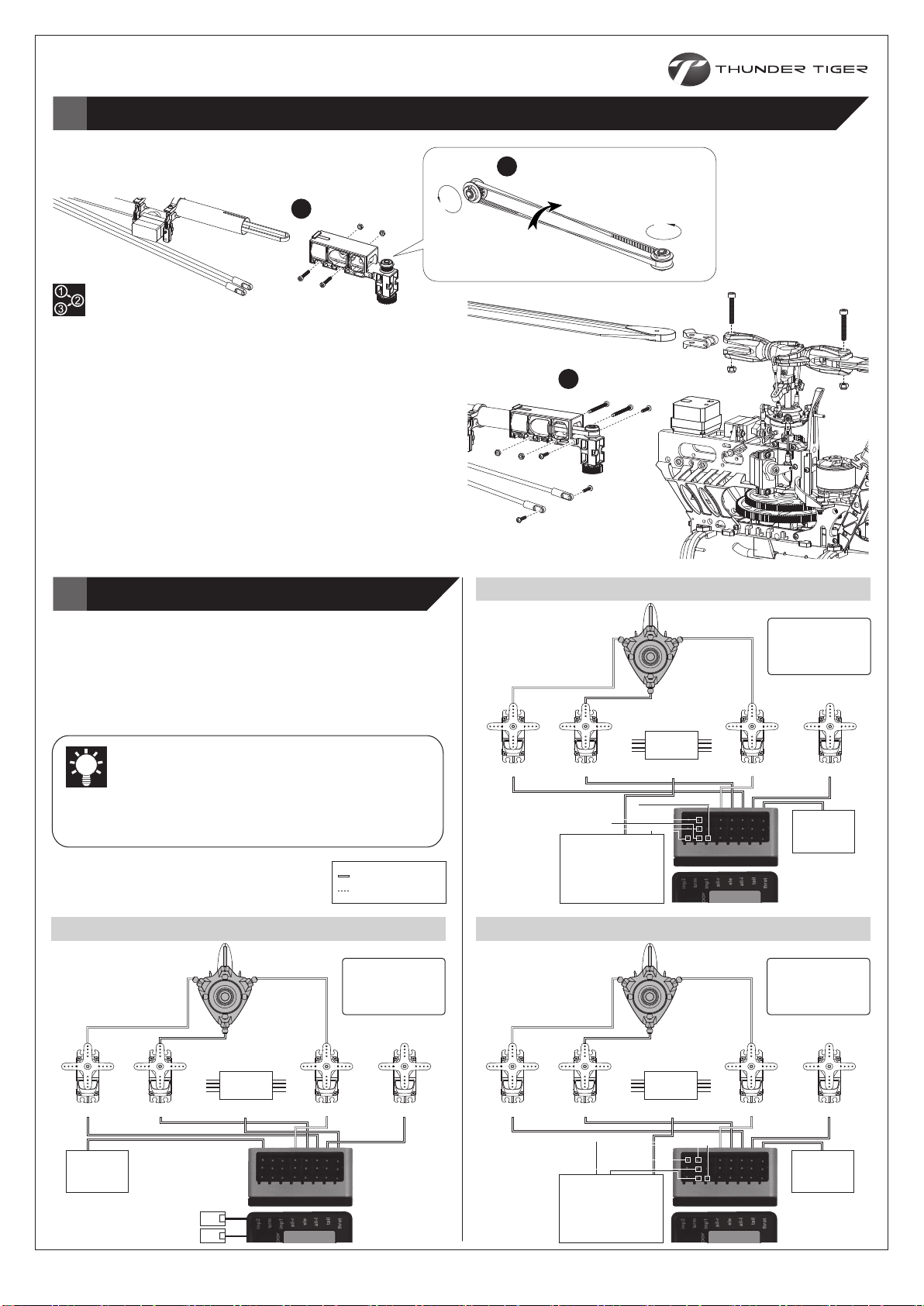
DEVICE CONNECTION 設備連接說明
1
。
BELT INSTALLATION
傳動皮帶安裝
C.C.W
逆時針旋轉
。
3
ACE RC / FUTABA / HITEC
Nose
機首
The wire connection between devices and receiver may differ in
different brand of radio system. The figures below are for your
reference, please read your radio system manual to find the
proper connections.
各品牌遙控系統的電子設備與接收機間接線方法或有差異,以下圖示為
安裝範例,實際接線方式請參閱您的遙控器說明書。
Although the Speed Controller (ESC) comes with the
ARF featuring a 5V BEC, to connect an additional
receiver battery pack could avoid any unexpected
shutdown of BEC.
完成機內附電子調速器具備BEC功能,額外使用一顆接收
機電池以可防止BEC意外斷電的情況。(BEC safe措施)
Servo Cable 連接線
Gain Wire 訊號線
SPECTRUM (DSM2 / DSMX)
CH2 / AUX1(CH6)*
AUX1(CH6) / CH2*
*CH2 & Aux1(CH6)
are Interchangeable
*CH2 & Aux1(CH6)
可互換
AUX1(CH6) / CH2*
JR
AUX1(CH6) / CH2*
Elevator升降舵
Rudder
Guin
Pitch
(BATT)
6-channel receiver
7 channel receiver
六動作接收器
七動作接收器
CH2 / AUX1(CH6)*
ESC速控器 Aileron右副翼
Aileron
Elevator
Throttle
CH2 / AUX1(CH6)*
*CH2 & Aux1(CH6)
are Interchangeable
*CH2 & Aux1(CH6)
可互換
Rudder尾舵Aileron左副翼
4.8-6.0V
Rx Battery
接收器電池
Additional Battery
for BEC Safe
*CH2 & Aux1(CH6)
are Interchangeable
*CH2 & Aux1(CH6)
可互換
4.8-6.0V
Rx Battery
接收器電池
Additional Battery
for BEC Safe
Elevator升降舵
Satellite Receiver
外接子天線
ESC速控器 Aileron右副翼
dsm
dsm
Rudder尾舵Aileron左副翼
Elevator升降舵
AUX 1
AUX 2
(BATT)
6-channel receiver
7 channel receiver
六動作接收器
七動作接收器
ESC速控器 Aileron右副翼
Throttle
Aileron
Elevator
Rudder
Rudder尾舵Aileron左副翼
4.8-6.0V
Rx Battery
接收器電池
Additional Battery
for BEC Safe
-4-
Page 6
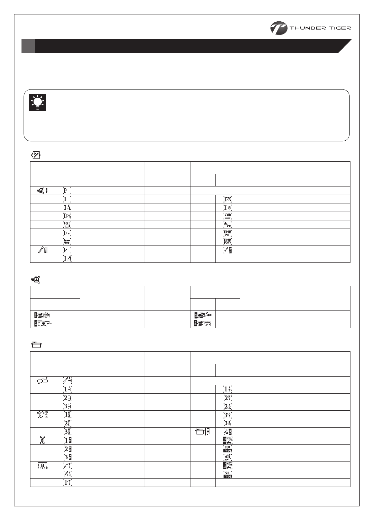
GT5.1 GYRO SETTING 三軸陀螺儀設定
The parameters of GT5.1 comes with the E325S were pre-set at factory, the detail values and its“Reset Default”in a separate
available GT5.1 are listed as below chart. Please read the instruction manual to learn more details on GT5.1 operations.
本完成機產品內附GT5.1陀螺儀已由原廠依E325S飛行特性調校完成,原廠E325S完成機預設值及單品銷售之GT5.1“重設預設值”如下表所示。
要了解GT5.1設定操作方式,請進一步詳閱GT5.1說明書。
Be careful! The GT5.1 is a high-tech & performance flybarless control system, and any changes of parameters may cause
unexpected situation during flights. Please ensure you had known the functions well before you do any adjustment. It is
strongly recommended to seek helps and guidance from accomplished pilot when adjusting the parameters of GT5.1 if you
were newcomer to the RC helicopters.
請小心! GT5.1是一項高科技且高性能的無平衡翼控制系統,任何設定值變更都可能造成飛行時出現預期外的動作。請在進行任何設定
調整前,務必確定您已對所有功能用途有充份認識。如果您是剛接觸遙控直昇機的初學者,強烈建議您尋求有經驗的玩家協助您調整
GT5.1參數值。
■ Function P/I 值設定功能
Level 選單層 Default parameters
at Factory for E325S
1 2
E325S原廠設定值
■ Function 十字盤設定功能
Level 選單層 Default parameters
at Factory for E325S
1 2
E325S原廠設定值
Elektro
■ Function 伺服機設定功能
60
60
100
30
90
18
4
70
65
100
Reset Default
重設預設值
70
70
100
25
85
18
4
60
70
Reset Default
重設預設值
Nitro
95
Level 選單層 Default parameters
at Factory for E325S
1 2
(Continue from left column…承左欄)
Level 選單層 Default parameters
1 2
E325S原廠設定值
22
10
0
25
0
0
0
at Factory for E325S
E325S原廠設定值
90
90
Reset Default
重設預設值
22
10
0
25
0
0
0
Reset Default
重設預設值
100
100
Level 選單層 Default parameters
at Factory for E325S
1
2
1
E325S原廠設定值
0
0
0
0
Rev
Norm
Rev
100
100
100
230
230
200
Reset Default
重設預設值
0
0
0
0
Norm
Rev
Rev
100
100
100
100
100
250
Level 選單層 Default parameters
at Factory for E325S
1 2
(Continue from left column…承左欄)
2
E325S原廠設定值
-5-
200
200
200
200
200
1500
0.045
166
120
0.045
166
Reset Default
重設預設值
250
250
250
250
250
1500
0.035
166
120
0.04
166
Page 7
1 The signal directions of vary brand radios may differ, please refer your transmitter instruction manual and page 7 of this manual “SWASHPLATE &
SERVO MOVEMENT SETTING” to set the proper directions.
2 The values on this function depends on the specifications of the servos you purchase, any wrong value set here may cause unexpected damage of
servos, please inquire the servo manufacture to know the specification in details.(The values here had already pre-set properly at factory for the
servos come with E325S.)
1 不同品牌遙控系統訊號方向會有所差異,請參考您的遙控器說明書及本說明書第7頁“十字盤及伺服機動作設定”來設定正確的舵機作動方向。
2 本功能內設定值取決於您所使用的舵機規格,任何錯誤設定值都可能造成舵機損壞,敬請向舵機製造商詢問詳細的規格數據。(該值已由原廠針對E325S所附舵機
正確設定完成。)
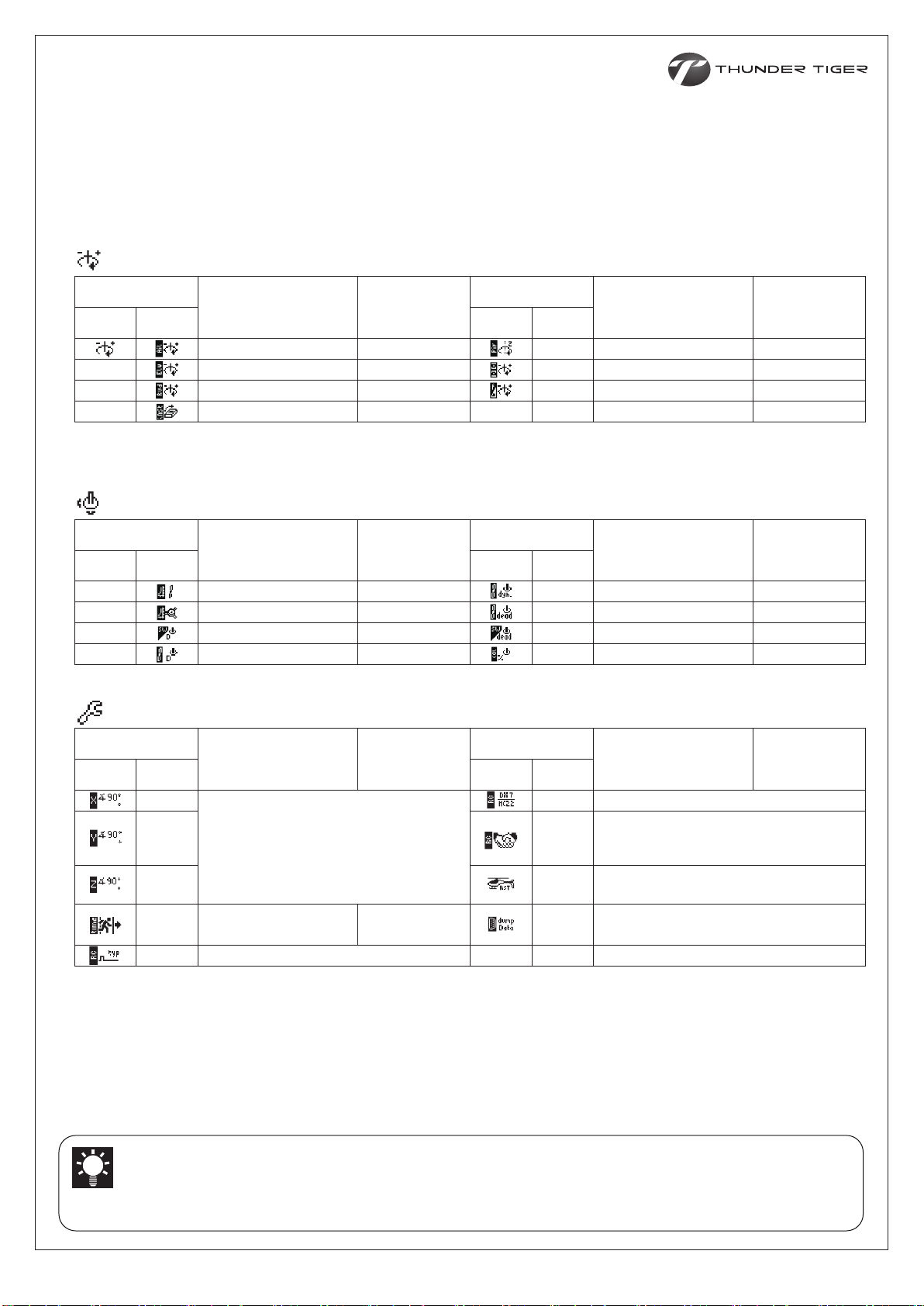
■ Function 陀螺儀設定功能
Level 選單層 Default parameters
at Factory for E325S
1
2
1
E325S原廠設定值
Norm
Norm
Rev
Rev
1 The signal directions of vary brand radios may differ, please read the GT5.1 instruction manual page 2 “Sensor Menu” to set the proper directions.
1 不同品牌遙控系統訊號方向會有所差異,請詳閱GT5.1說明書第2頁“陀螺儀設定”來設定正確的舵機作動方向。
Reset Default
重設預設值
Rev
Rev
Norm
Rev
Level 選單層 Default parameters
at Factory for E325S
1 2
E325S原廠設定值
Norm
5
2
Reset Default
重設預設值
Norm
■ Function 撥桿設定功能
Level 選單層 Default parameters
at Factory for E325S
1 2
E325S原廠設定值
25
25
0
0
Reset Default
重設預設值
25
25
0
0
Level 選單層 Default parameters
at Factory for E325S
1 2
E325S原廠設定值
25
0
0
10
Reset Default
重設預設值
■ Function 工具
5
2
25
0
0
10
Level 選單層 Default parameters
at Factory for E325S
1
2
E325S原廠設定值
Reset Default
重設預設值
Level 選單層 Default parameters
at Factory for E325S
1 2
E325S原廠設定值
Reset Default
重設預設值
DX7
Functions for sensor calibrations,
DO NOT touch these values.
工程用途,請勿更動。
2
Refer the GT5.1 and your radio instruction
manuals to learn how to binding.
請參閱GT5.1及遙控器說明書完成對頻。
Recover “Reset Default” parameters
重設為預設值
25 Seconds 50 Seconds
1
1 3 systems of receiver may alternative: Standard Rx, Futaba S-bus or Spectrum Compatible, which depends on the radio system you use. Please refer
page 4 of this manual to know the correct device connections according to your radio brand.
2 Only used with Spectrum satellites; please refer your radio instruction manual if using a standard Rx or Futaba S-bus systems to execute binding.
To binding a Spectrum Tx and Rx: Activate the menu and both satellite LEDs will flash- placing the GT5.1 into “Bind” mode. Turn on the Tx whilst
holding in the bind-button. Binding is completed when the satellite LEDs remain solid.
1 依您所使用的接收機系統選用:標準接收機、Futaba S-Bus或Spectrum相容系統。並依所使用的遙控器品牌正確完成電子設備配線,說明請詳閱本說明書第4頁。
2 僅適用於Spectrum外接子天線;如使用標準接收機或Futaba S-bus系統,請翻閱您的遙控器說明書來執行對頻。
Spectrum對頻程序:進入本功能選單,此時子天線LED燈為快閃狀態,使GT5.1進入“對頻”模式。按住發射機上對頻功能鍵並開啟發射機電源,當子天線上LED
停止閃爍時,表示對頻完成。
Standard Rx
No function as yet and should not be used.
功能保留,無需設定
To set the Fail-Safe function on your helicopter as well for safety is strongly recommended. Please refer your radio
instruction manual to learn how to set the FS function if using a Standard Rx or Futaba S-bus. If using a Spectrum
compatible Rx, please refer the page 2 of GT5.1 manual “Fail-safe Configuration upon DSM2/X”.
安全起見,強烈建議您也同時設定“安全回復”功能。如使用標準接收機或Futaba S-bus系統,請翻閱您的遙控器說明書來完成設定
。如您使用Spectrum相容系統,請詳閱GT5.1說明書第2頁“DSM2/X系統安全回復設定”。
-6-
Page 8

MODEL & SWASHPLATE SETTING 模型及十字盤模式設定
Before starting, ensure the following preparation is done.
1. Set all trims, knobs and switches to the neutral position.
2. Reset the radio to its factory preset position.
3. Choose the “Normal (non-mixing)”swashplate control mode.
The control system of E325S is a 120° CCPM, but please set the swashplate control mode on you
transmitter in “Normal (non-mixing)”since the mixing function is leaded by the GT5.1 flybarless control
system which comes with the E325S ARF.
設定發射機前,請確認以下注意事項:
120
120
1. 發射機上所有調整旋鈕、機構均位於中立點
2. 恢復設定值為原廠內建數據
3. 十字盤模式請選用“Normal (無混控)”模式
E325S的控制系統為120度CCPM模式,但因為混控功能將由E325S附機上的GT5.1無平衡翼控制系統主導,因此請
將遙控器上的控制模式設為“Normal (無混控)”。
SWASHPLATE & SERVO MOVEMENT SETTING 十字盤及伺服機動作設定
The movement direction of servo may differ in different brand of radio system; Power on your transmitter and receiver, please refer
the figure below to ensure the direction of swahplate and servo movement are correct, as well as observe if there is any bind or
interference when the servo reaches to the maximum travel point.
各品牌遙控系統伺服機方向訊號或有不同,請依序開啟發射機及接收機,參閱以下圖示確認十字盤及伺服機作動方向正確,同時觀察伺服機作動達最
大行程量時,是否有行程量過大或干涉情況。
Aileron
副翼
Elevator
升降舵
Pitch
螺距
Rudder
尾舵
Mode 1 Mode 2
Front View/前視圖
Right Side/右側
Front View/前視圖
Left Side/左側
Servo Horn movement
伺服機擺臂動作
Check Point
機構動作確認
Front View / 前視圖
Right View / 右視圖
Right Side/右側
Front View / 前視圖
If the movements of servos or swashplate are incorrect, please refer your transmitter manual to turn on the “Servo Reverse” function
for one or more channels in your transmitter.
If there’s any bind or interference when reaching the maximum servo travel point, please also refer your transmitter manual to reduce
the “Travel Adjustment (or End Point Adjustment)” value in your transmitter.
如伺服機或十字盤動作方向錯誤,請參閱您的遙控器說明書,開啟遙控器上的伺服機逆轉功能。
如伺服機最大行程量過大或發生干涉,請參閱您的遙控器說明書,降低伺服機行程量設定值。
For safety, to set a Fail Safe function per your transmitter instruction manual at this step as well is strongly recommended.
安全起來,建議您參閱遙控器說明書,在此步驟中同時設定“安全回復”功能。
-7-
Page 9
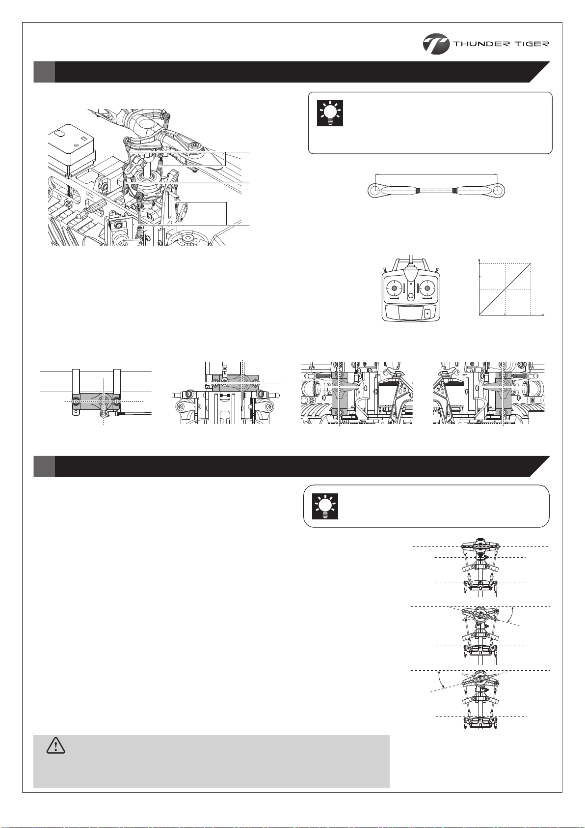
LINKAGES AND SERVO NEUTRAL ADJUSTMENT 連桿及伺服機中立點調整
0°
+15°
-15°
■ Lengths of Linkage Rods 連桿長度設定值
44.25mm
20mm
Length measured from ball link center to ball link center
36.5mm
由此連桿頭中心測量至另一頭連桿頭中心
■ Servo Neutral Position 伺服機中立點
Adjust the Pitch and Throttle Curves as a -45° straight line (from 0 to highest 100%
and pass through the mid-point 50%) on your transmitter firstly. Refer the figure
below to ensure every servo is at its neutral positions when the sticks of transmitter
are at its neutral position before setting the corrective pitch. Refer your transmitter
manual to adjust the “Sub-Trim” values if the servos are not at its neutral position.
首先將油門曲線設定為負斜率之對角線。參閱右圖,確認所有伺服機皆正確對應遙控器撥桿中
立點位置。如果伺服機偏離中立點,請參閱您的遙控器說明書使用“Sub-Trim”進行微調。
The proper lengths of linkages on the helicopter
have been setup correctly at Factory, but may need
to be slightly adjusted per the actual conditions.
直昇機上連桿已由原廠組裝完成,但長度可能仍需視實際
情況略做調整。
L M H
Both Stickers are at their
neutral positions.
撥桿皆位於中立點位置
[Pitch / Throttle Curve]
Point L : 0%
Point M : 50%
Point H : 100%
Tail Servo
尾舵伺服機
Elevator Servo
升降舵伺服機
Aileron Servo - Right
副翼伺服機—右
COLLECTIVE PITCH RANGE SETTING 螺距範圍設定
All linkages and servos should be at their neutral positions if you have
done the adjustment correctly per the description above. The steps
below will define the limits of the collective pitch setting.
正確依照上述完成設定,所有連桿及伺服機皆應會位於其中立點位置。以下
步驟將設定主旋翼螺距的範圍值。
■ Centering 中立點
1. The elevator and aileron control levers should be as the drawing right while centering the
collective pitch stick.
2. The flybar, the main blades should be at 0 degree and the swashplate should be level.
1. 當發射機螺距撥置中時,升降舵面及副翼控制搖臂位置應成水平狀態。
2. 主旋翼與穩定翼平行,兩者間角度為0,且十字盤為水平狀態。
■ Maximizing 最大螺距設定
1. Place the collective stick at high end.
2. The main blades should be at +15 degree and the swashplate should be level.
1. 將發射機螺距撥上推至最高點。
2. 主旋翼相對於穩定翼呈+15度角,且十字盤為水平狀態。
■ Minimizing 最小螺距設定
1. Place the collective stick at low end.
2. The main blades should be at -15 degree and the swashplate should be level.
1. 將發射機螺距撥上撥至最低點。
2. 主旋翼相對於穩定翼呈-15度角,且十字盤為水平狀態。
A pitch gauge (available separately) may be required
to measure the accurate collective pitch.
使用螺距尺(另購)才能精確量測聚合螺距攻角。
Aileron Servo - Left
副翼伺服機—左
CAUTION / 警告
The setting of the maximum collective pitch depends on your personal flying skill and style.
Too much collective pitch could overload the engine and drive system.
請依個人飛行技巧及習慣來設定最大螺距。過大的角度會增加引擎及傳動系統的負荷而縮短壽命。
-8-
Page 10

TAIL AND GYRO SETTING 尾舵及陀螺儀設定
The Gyro and the servo horn have been mounted on the helicopter at Factory. To power off the receiver and then transmitter before we
start to set gyro and tail at this step. 陀螺儀及伺服機擺臂已由原廠安裝完成。在開始設定陀螺儀及尾舵前,請依序關閉接收機及遙控器電源。
■ Gyro Operating Direction 陀螺儀作動方向
Power on your transmitter and then receiver again, do not move the helicopter at this moment until the LED indicator is steady.
Check the directions below:
1. While giving the right rudder control, the servo arm should move toward the nose of helicopter.
2. Rotate the helicopter with your hand counter clockwise, the servo
arm should move toward the nose of helicopter.
Please switch the direction on your transmitter or gyro if any wrong.
再次依序開啟遙控器及接收機,此時請勿移動直昇機,直到陀螺儀上燈號
恆亮為止;確認方向:
1. 當執行右舵時,伺服機擺臂應朝機頭方向作動。
2. 將整台直昇機逆時針旋轉時,伺服機擺臂應朝機頭方向作動。
如方向有誤請切換遙控器或陀螺儀上正逆轉方向。
Rudder Servo
尾舵伺服機
■ Length of Tail Linkage Rod 尾舵拉桿長度
The servo horn should be at neutral position while the tail sticker of transmitter
is centered, and the pitch of tail rotor grips should be at 0-degree or a little bit
offset to right. Please adjust the linkages if the length of rod is incorrect.
當遙控器尾舵撥桿置中時,伺服機擺臂也應位於中立點位置,且尾旋翼螺距為0度,或
稍偏向右。如拉桿長度不正確,請調整球頭。
The traveling limit of the tail servo may not go beyond the mechanical movement.
To adjust the traveling limit or pirouetting speed of the helicopter, please use the “Travel Adjustment” , “D/R” or “EXP”
functions on your transmitter. Refer your transmitter or gyro instruction manual may get more detailed information.
尾舵伺服機最大行程量切勿超過機械行程量。要調整行程量或尾舵自旋速度,請使用遙控器上“行程設定”,“大小動”或“指數值”
功能。請詳閱您的遙控器說明書以獲得更多資訊。
Rudder Servo
尾舵伺服機
ESC SETTING 電子調速器設定
To connect the Lipo battery pack to ESC is necessary at this step. For safety, please ensure the motor has been deactivated
(or disengage the pinion gear from the main gear), and will not drive the main rotor before performing this step!
在設定程序中,必需將鋰電池連接至電子調速器。安全起見,請再次確認馬達不會被啟動(或將馬達齒脫離主齒盤),且不會驅動主旋翼。
All the parameters of the ESC (Electric Speed Controller) had been set at
Factory, the only setting you need to do is the Throttle Calibration:
電子調速器各項參數已由原廠內建完成,您只需進行油門校正程序即可:
1. Power on the transmitter and place the throttle stick at full throttle position.
2. Power on the receiver if do not the built-in BEC.
3. Connect Lipo battery pack to ESC and wait for 2 seconds.
4. You will hear 6 tones (♪♪♪♪♪♪) from the ESC, which means the full throttle position has been calibrated.
5. Move the throttle stick to the idle position (lowest position) for about 1 second, and then you will hear 4 tones. (♪♪-♪♪)
6. A long Beep- tone means the idle throttle position has been calibrated and now the ESC is ready to go.
7. Power off the receiver/disconnect the Lipo battery pack from ESC, and then your transmitter.
8. To confirm the calibration procedure had been done correctly, please re-power on the transmitter and then re-connect Lipo battery
pack to ESC again. You will hear 3 rising tones (♪♪♪) if the setting of ESC is correct and ready to go.
1. 開啟遙控器,將油門撥桿置於全油門位置。
2. 如未使用內建BEC功能,請開啟接收機。
3. 將鋰電池組(另購)連接至ESC,等待2秒。
4. ESC會發出6聲“嗶”響,表示全油門位置已完成校正並紀錄。
5. 將油門撥桿移至最低點並等待1秒,此時ESC會發出4聲音響。
6. 當聽到ESC發出一長“嗶”聲時,表示油門最低點位置已完成校正並紀錄,此時ESC已完成校正程序並已可正常使用。
7. 關閉接收機電源/斷開鋰電池組與ESC間的連接,然後再關閉發射機電源。
8. 重新依序開啟發射機電源及連接電池至速控器,以確認校正程序是否正確完成;聽到3聲上抑音響表示已ESC校正設定正確且已可飛行。
Please refer the ESC instruction manual to read more detailed
information if any default settings need to be changed.
如有任何設定需要變更,敬請參閱電調說明書以獲得更詳細的資訊。
The calibration procedure always must be
preformed if a new transmitter is being used.
新使用或更換遙控器時,請務必執行校正程序。
Congratulates all the setting on the grand had been done for now. Next section of setting will be moved on the flying field and
need to take your helicopter off. Therefore, it is strongly recommended to seek helps and guidance from accomplished pilots if
you were a newcomer to the RC helicopters!
至此,您已完成所有的靜態設定。下一步設定需要至飛場進行,並將直昇機升空,如果您是剛接觸模型直昇機的初學者,我們強烈建議您尋
求有經驗的玩家給予協助及指導!
-9-
Page 11

CURVE SETTING 曲線設定
The following is the setting up data of pitch curve and throttle curve for your reference only. Please ask experienced pilot to help you if
you have never done this before.
下列參數設定僅供參考,請依實際狀況進行調整,或詢求有經驗的玩家協助。
■ Beginner / 一般飛行
Throttle Curve 油門曲線
Thro.
油門
100
Pitch Curve 螺距曲線
Pitch
螺距
100
Throttle Curve 油門曲線
00253550507565100
Normal 一般飛行
100
撥桿
75
50
25
0 25 50 75 100 Stick
75
50
25
0 25
50 75 100 Stick
■ 3D
Throttle Curve 油門曲線
Thro.
油門
100
75
50
25
0 25
◎ Normal / 一般飛行 ◎ Idle / 特技模式 1
50 75 100 Stick
撥桿
100
75
50
25
0 25
Thro.
油門
撥桿
50 75 100 Stick
撥桿
Pitch Curve 螺距曲線
03525-507075-100
Normal 一般飛行
Pitch Curve 螺距曲線
0
Normal 一般飛行
-4°25-
Throttle Curve 油門曲線
0
25
0
Normal 一般飛行
Idle-up 1 特技模式 1
35
100
Pitch Curve 螺距曲線
0
25
Normal 一般飛行
Idle-up 1 特技模式 1
Hold 鎖定模式
35
0
0
-
-
-
-
50
+6°75-
50
50
60
50
70
-
-
75
65
75
-
-
-
-
85
100
+10°
100
100
100
100
85
100
100
Pitch Curve 螺距曲線
Pitch
螺距
100
75
50
25
0 25
50 75 100 Stick
◎ Normal / 一般飛行
Pitch
螺距
◎ Hold / 鎖定模式
100
75
50
25
撥桿
0 25
◎ Idle / 特技模式 1
Pitch
螺距
Pitch Curve 螺距曲線
0
25
50
75
100
-4°
-
+6°
-
-
-
+10°
+15°
+15°
Normal 一般飛行
-15°
-
-
-
-
50 75 100 Stick
撥桿
Idle-up 1 特技模式 1
Hold 鎖定模式
-15°
CAUTION / 警告
1. Too much collective pitch will bring about too much loading to the motor
and drive system.
2. Too much headspeed will lead to blades (grips) explosion.
3. It's very dangerous for setting the headspeed over the blades (grips) limit.
4. Please do not set the collective pitch to the maximam (±15) unless you
have very good collective pitch management skill.
1. 過大的聚合螺距設定會使馬達及傳動系統超載。
2. 過快的主旋翼轉速會造成主旋翼轉座崩裂或射槳。
3. 將旋翼轉速設定超過槳片負載極限極端危險!
4. 請勿將聚合螺距設定超過最大值(±15度角)。
-10-
Page 12

BLADE TRACKING ADJUSTMENT 主旋翼軌跡調整
CAUTION / 警告
For safety, ensure to keep a safe distance from the helicopter at least 5 meter (15 feet) while making tracking adjustment.
安全起見,進行主旋翼軌跡調整時,請至少與直昇機保持5米(15呎)的安全距離。
color tape / 色標貼
Out of Track / 雙槳
Adjustment is
necessary.
需要調整
1. Use a color tape at the tip of main blades for tracking identification easily.
2. Increase the main blade speed for slight lift-off.
3. Observe which blade appears to be lower than the other, and increase the
pitch of the lower blade for one turn of the Linkage Rod at a time until
each blade runs in track. If both main blades rotate in the same path, it
doesn,t need to be adjusted.
1. 在主旋翼前端貼上色標可方便辨識軌跡。
2. 提高主旋翼轉速使機體稍懸浮於地面。
3. 觀察兩支旋翼軌跡是否有落差(雙槳),調整軌跡較低旋翼上的連桿長度,一次
調整一圈,直至兩支旋翼軌跡一致。若軌跡一致則無需調整。
color tape / 色標貼
In Track / 軌跡正確
Adjustment is
unnecessary.
不需要調整
Linkage Rod
連桿
CAUTION / 警告
Out of track will cause vibration, instability and a loss of power due to additional drag. Please adjust the tracking repeatedly until
the blades are in track properly.
旋翼軌跡落差(雙槳)會造成直昇機震動、不平衡及損失動力。請務必進行調整以使旋翼軌跡精準正確。
Congratulates all the setting for your helicopter have been done and ready to fly right now. It is strongly recommended
to seek helps and guidance from accomplished pilots if you were a newcomer to the RC helicopters!
恭禧您已完成直昇機所有設定並可準備起飛。如果您是剛接觸模型直昇機的初學者,我們強烈建議您尋求有經驗的玩家給予協助及
指導!
-11-
Page 13

CAUTIONS OF LI-PO BATTERY PACK USING
Lithium Polymer (Li-Po) battery is volatile. Failure to read and follow the safety instructions or the instruction manual offered by
manufacturers may result in fire, personal injury and damage to property if charged or used improperly.
Please READ your Li-Po battery manual thoroughly before using. Some precaution and information for your reference below:
1. ONLY use a charger specifically designed for Li-Po battery packs to charge/discharge your Li-Po battery packs. Failure to use an
improper charger may cause a fire, which may result in personal injury and property damage.
2. A parallel charging process is strongly recommended, otherwise, the balancer is necessary if using a serial charging process.
3. Gernally DO NOT over charge the battery over the maximum voltage of 4.2V/per cell and over discharge drop below 3.7V/per cell.
4. Always keep the voltage of every cell at 3.8V if the pack will be stored for a long term.
5. Always avoid any puncture of the battery pack at all times.
Neither Thunder Tiger nor our distributoers/retailers assume liability for failures to comply with these cautions, safety recommended
and instruction manual. Users assume all risks associated with Li-Po battery packs.
鋰聚電池具有相當危險性。疏於詳閱以下注意事項及電池廠商所提供的說明書或未依據正確操作方式使用,可能會引發火災、人身傷害及財產損失。
請務必在使用前詳閱並遵守使用說明。以下注意事項及訊息提供您參考:
1. 請務必使用鋰聚電池專用充電器充/放電鋰聚電池組。使用不正確的充電器可能會引發火災、人身傷害及財產損失。
2. 強烈建議使用平行充電式的充電器充電。若使用串充方式請務必加裝平衡器。
3. 請勿過度充電使電壓超過4.2伏特/單一電池蕊,或過度放電使電壓低於3.7伏特/單一電池蕊。
4. 如需長期儲存電池,請保持單一電池蕊電壓在3.8伏特。
5. 任何情況下,皆勿擠壓電池。
雷虎科技或授權經銷商/模型店對未依照正確方式使用或安並規定之意外具免責條款,使用人應自負使用鋰聚電池所可能衍生的風險。
鋰聚電池使用注意事項
INSTRUCTION OF LI-PO BATTERY CHARGER
The ACE RC T3AC BALANCE CHARGER is specifically-designed
for charging 2-cell and 3-cell Li-Po battery packs. The compactsize charger features built-in switch adaptor for input power
source and individual cell balancing function for safe charging.
ACE RC T3AC是2至3片式鋰電池專用充電器,具備高安全性之分壓
充電及平衡功能,並內建變壓轉換,迷您體積中的強大的功能絕非其
他市售充電產品可比擬 !
Connect to 3-Cell Li-Po Battery
連接 3-Cell 鋰電池(11.1V)
Connect to 2-Cell Li-Po Battery
連接 2-Cell 鋰電池(7.4V)
Caution 注意事項:
1. ONLY for 2-cell & 3-cell Li-Po battery.
2. Proceed with charging in a safe environment.
3. DO NOT charge while the battery is still warm.
4. DO NOT charge an expanded or damaged battery.
5. Keep the charger away from humidity.
1. 限用於2或3片式鋰電池組。
2. 請於安全環境中進行充電。
3. 電池仍處於發熱狀態時,請勿充電。
4. 電池發生膨脹或受損,請勿充電。
5. 請勿於潮溼環境中使用。
鋰電池充電器使用說明
Specification 基本規格:
規格摘要
Power supply voltage
母電源電壓
Cell count range
適用電池片數
Max. charge current
最大充電電流
Dimension approx
尺寸
Weight approx
重量
Charger LED Status 充電器LED狀態說明:
Operational mode display
使用狀態顯示方式
Power on
開啟電源時
Stand By
待機狀態
Charging
充電中
Full
完成充電
Fault
失敗
* Re-Plug the AC Plug and Battery if faults.
顯示失敗燈號時,請重新安插AC電源插頭及電池。
規格
110-240V AC
2-3cells
3×650mA
100×60×35mm
180g
via 3 LEDs
Orange (1 second) / 橘燈(停留1秒)
Green / 綠燈
Red / 紅燈
Green / 綠燈
Flashing / 快閃燈號
AFTER FLIGHT CHECKLIST
(1) Check every screw and bolt to make sure none has loosens due to vibration.
(2) Check every rotating and movable part to ensure they still move smoothly and normally.
(3) Clean off the exhaust residue from the muffler, motor, and helicopter.
(4) Check all movable parts, such as gears, ball links, etc. for unusual wear.
(1) 每次飛行後必須詳細的檢查機體的各部位螺絲有無鬆動情形,若發生鬆動必須確實鎖緊再進行下飛行。
(2) 每次飛行後檢查每一個轉動部位(含單頭連接桿)均能順暢的運作。
(3) 排氣管、馬達、直昇機本體必須確實的清潔。
(4) 檢查每一個動作部位,齒輪、球頭等是否有不正常磨損。
飛行後的檢查項目
-12-
Page 14

MAIN ROTOR HEAD 主旋翼頭
Add a drop of threadlocker on the thread of screws when securing into the parts which are made of metal.
螺絲鎖固於金屬製品零件時,請酌沾適量防鬆膠。
Apply some amount of silicon oil or
Vaseline on the Spindle for easy assembly.
在橫軸上塗抹些許矽膠油脂或凡士林,可使組
裝更為容易。
PV1246
PV0781
PV0048
PV0707
PV1293
PV1294
PV0710
PV0727
PV1290
PV1292
Diagram for Thrust Bearing Assembly
止推軸承安裝示意圖
Large Internal
Diameter
always go toward the
Main Rotor Hub
內徑較大的一側,面向主
旋翼中心座組(內側)。
θA
PV0771
Small Internal
Diameter
always go toward the
Blade
內徑較小的一側,面向
主旋翼組(外側)。
PV0769
PV0781
θBθB
PV0783
Hint
組裝提示
Assemble left and right side
L
the same way
左右側組件相同
R
PV0807
Apply threadlocker
使用螺絲防鬆膠
-13-
Checking Tips :θA >θB
轉動角度 :θA >θB(轉動角度大者,內孔大;轉動角度小者,內孔小)
44.25
X2
Ensure smooth, non-binding
movement when assembling
確認組件靈活度
Apply grease
使用潤滑油膏(黃油)
Page 15

SPARE PARTS LIST 維修零件包表格
No. Description Note中文名稱
PV0048 BALL BEARING (d4xD8xW3) 軸承組 BEARING (d4xD8xW3) x 2
PV0707 FEATHERING SHAFT 固定軸
PV0710 SWASHPLATE 十字盤
PV0727 MAIN SHAFT LOCK RING 止擋圈 SET SCREW (M3x3) x 4
PV0769 THRUST BEARING (d4xD9xW4) 止推軸承組 THRUST BEARING (d4xD9xW4) x 2
PV0771 BALL BEARING (d4xD9xW4) 軸承組 BEARING (d4xD9xW4) x 4
PV0781 SCREW BAG 螺絲包 WASHER (d2.8xD5xW0.5) x 2, WASHER (d4xD7xW1) x 2
PV0783 SOCKET SCREW 內六角螺絲 SOCKET SCREW (M2.6x8) x 20
PV0802 HARDENED MAIN SHAFT 高強度主軸 SOCKET SCREW (M2x14) x 2, NUT(M2) x 4
PV1246 FLAP DAMPER 避震墊圈
PV1290 FBL LINKAGE ROD 無平衡翼連接桿 35mm x 4
PV1292 FBL MAIN ROTOR GRIP 無平衡翼主旋翼轉座 WASHER (d2.8xD5xW0.5) x 2, WASHER (d7xD9xW1) x 2
SOCKET SCREW (M2.6x8) x 2, COUNTERSUNK SCREW (M1.6x6) x 2
PV1293 FBL WASHOUT BASE 無平衡翼控制座 SOCKET SCREW (M2x6) x 2, E-CLIP (1.5mm) X 2
PV1294 FBL METAL MAIN ROTOR HUB 無平衡翼金屬主旋翼固定座 SOCKET SCREW (M2x14), SOCKET SCREW (M2x6) x 2, NUT(M2) x 2
-14-
Completed View
組裝完成
Page 16

MAIN FRAME ( SKID & MOTOR ) 本體(腳架&馬達)
Add a drop of threadlocker on the thread of screws when securing into the parts which are made of metal.
螺絲鎖固於金屬製品零件時,請酌沾適量防鬆膠。
PV0718
PV0059
PV0717
2382
PV0718
PV0729
PV0728
PV0720
PV0721
PV0714
Hint
組裝提示
Assemble left and right side
L
the same way
左右側組件相同
R
PV0719
PV0059
PV0715
PV0903
Apply threadlocker
使用螺絲防鬆膠
-15-
Page 17

SPARE PARTS LIST 維修零件包表格
No. Description Note中文名稱
2382 OBL 29/37-10H 無刷馬達
PV0059 BALL BEARING (d5xD11xW5) 軸承組 BEARING (d5xD11xW5) x 2
PV0714 MAIN FRAME 主機體 TAPPING SCREW (M2x6) x 8
PV0715 BASE PLATE 底座 TAPPING SCREW (M2x6) x 18, TAPPING SCREW (M2x10) x 12
PV0717 UPPER BRG HOUSING 上軸承座組 TAPPING SCREW (M2x10) x 8
PV0718 SERVO TRAY 伺服機座組 TAPPING SCREW (M2x6) x 4, TAPPING SCREW (M2x10) x 2
PV0719 BATTERY TRAY 電池座組 TAPPING SCREW (M2x6) x 8, TAPPING SCREW (M2x10) x 2
PV0720 BODY RETAINING POST 機身固定支柱組
PV0721 PHASE CONTROL TRACK 相位控制導軌 TAPPING SCREW (M2x6) x 2
PV0728 MOTOR MOUNT 馬達固定座 SOCKET SCREW (M3x5) x 2, SOCKET SCREW (M3x10) x 2
NYLON NUT (M3) x 2
PV0729 PINION 13T 驅動齒輪13T SET SCREW (M3x3) x 2
PV0903 LANDING SKID (BLACK) 腳架(黑色) TAPPING SCREW (M2x6) x 4, TAPPING SCREW (M2x10) x 2
Completed View
組裝完成
-16-
Page 18

MAIN GEAR 主齒輪
Add a drop of threadlocker on the thread of screws when securing into the parts which are made of metal.
螺絲鎖固於金屬製品零件時,請酌沾適量防鬆膠。
PV0726
PV0722
PV0723
PV0785
PV0234
PV0727
Apply threadlocker
使用螺絲防鬆膠
Ensure smooth, non-binding
movement when assembling
確認組件靈活度
-17-
Hint
組裝提示
Page 19

SPARE PARTS LIST 維修零件包表格
No. Description Note中文名稱
PV0234 NUT 六角螺帽 NUT (M2) x 20
PV0722 TAIL DRIVE GEAR (124T) 尾驅動輪(124T)
PV0723 MAIN GEAR (150T) 主齒輪(150T)
PV0726 ONE WAY SHAFT 單向軸套組 WASHER (d3xD10xW0.3) x 2
PV0727 MAIN SHAFT LOCK RING 止擋圈 SET SCREW (M3x3) x 4
PV0785 SOCKET SCREW 半牙內六角螺絲 SOCKET SCREW (M2x14) x 20
Completed View
組裝完成
-18-
Page 20

TAIL UNIT (RUDDER SERVO) 尾部總成(尾舵伺服機)
Bag F
Add a drop of threadlocker on the thread of screws
when securing into the parts which are made of metal.
螺絲鎖固於金屬製品零件時,請酌沾適量防鬆膠。
PV0736
PV0743
PV0741
PV0740
PV0048
PV0749
PV0770
PV0750
PV0770
PV0739
PV0770
PV0742
PV0776
PV0762
PV0748
PV0749
PV0049
PV0737
PV0736
PV1156
PV0753
BELT INSTALLATION
傳動皮帶安裝
Tail 機尾
C.C.W
逆時針旋轉
Twist the belt toward right for 90
皮帶向右扭轉90
。
PV0733
PV0735
C.C.W
逆時針旋轉
。
Nose 機首
PV0732
PV0732
Assemble left and right side
L
the same way
左右側組件相同
R
PV0751
Apply threadlocker
使用螺絲防鬆膠
-19-
8161
PV0747
PV0752
Ensure smooth, non-binding
movement when assembling
確認組件靈活度
Hint
組裝提示
Page 21

SPARE PARTS LIST 維修零件包表格
No. Description Note中文名稱
8161 MICRO DIGITAL SERVO, DC0915 迷你數位伺服機, DC0915
PV0048 BALL BEARING (d4xD8xW3) 軸承組 BEARING (d4xD8xW3) x 2
PV0049 BALL BEARING (d3xD8xW4) 軸承組 BEARING (d3xD8xW4) x 2
PV0732 TAIL BOOM BRACKET 尾管固定座
SELF TAPPING SCREW (M2x10) x 2, TAPPING SCREW (M2x10) x 2
PV0733 TAIL DRIVE GEAR SET 尾驅動齒輪組
PV0735 TAIL DRIVE BELT MXL-3T (413T) 時規皮帶
PV0736 TAIL UNIT CASE SET 尾座組 TAPPING SCREW (M2x10) x 6
PV0737 TAIL ROTOR SHAFT 尾旋翼軸組
PV0739 TAIL PITCH CONTROL LINK 尾旋翼連接頭 SHOULDERED SCREW (M2x10) x 4
PV0740 TAIL ROTOR GRIP 尾旋翼夾座組 SOCKET SCREW (M2x8) x 2, SHOULDERED SCREW (M2x10) x 2
PV0741 TAIL ROTOR HUB 尾旋翼固定座 SET SCREW (M3x3) x 1
PV0742 TAIL ROTOR BLADE 尾旋翼片
PV0743 TAIL FIN SET 安定面組 TAPPING SCREW (M2x10) x 2
PV0747 TAIL SERVO TRAY 尾伺服機座 TAPPING SCREW (M2x10) x 2
PV0748 DOUBLE JOINT LEVER 雙關結連桿 SOCKET SCREW (M2x16) x 2
PV0749 TAIL PITCH CONTROL LEVER 尾旋翼控制桿 TAPPING SCREW (M2x10) x 1, COUNTERSUNK SCREW (M1.6x6) x 1
PV0750 TAIL PITCH CONTROL SLIDER 尾旋翼控制滑座
PV0751 TAIL SUPPORT BRACKET 尾支撐桿座 SOCKET SCREW (M2x16) x 1, NUT (M2) x 1
PV0752 TAIL SUPPORT 尾支撐桿組
PV0753 TAIL LINKAGE ROD 尾拉桿組 270mm x 2
PV0762 TAIL ROD GUIDE 固定環 SELF TAPPING SCREW (M1.2x6) x 2
PV0770 BALL BEARING (d2xD5xW2.5) 軸承組 BEARING (d2xD5xW2.5) x 10
PV0776 SOCKET SCREW 內六角螺絲 SOCKET SCREW (M2x16) x 20
PV1156 TAIL BOOM (356mm) 尾管
SOCKET SCREW (M2x12) x 2, SOCKET SCREW (M2x25) x 2, NUT (M2) x 4
SOCKET SCREW (M2x16) x 1, NUT (M2) x 1, TAPPING SCREW (M2x10) x 2
-20-
Completed View
組裝完成
Page 22

TAIL BOOM & CYCLIC SERVO 尾管與舵面伺服機
The distance from the center of the
servo horn to both sides of the linkage
balls should be the same.
伺服機擺臂中心至兩邊球頭距離必需相等。
//
//
(A)
PV0754
PV0755
(B)
8161
PV0754
PV0755
8161
PV0779
PV0773
PV0234
PV0773
8161
(B)
PV0754
PV0755
20
(A)
36.5
(B)
X2
Ensure smooth, non-binding
movement when assembling
確認組件靈活度
Hint
組裝提示
-21-
Page 23

SPARE PARTS LIST 維修零件包表格
No. Description Note中文名稱
8161 MICRO DIGITAL SERVO, DC0915 迷你數位伺服機, DC0915
PV0234 NUT 六角螺帽 NUT (M2) x 20
PV0754 LINKAGE ROD 連接桿組 7mm x 3, 24.5mm x 2
PV0755 BALL LINK 單頭連接桿
PV0773 TAPPING SCREW 墊圈自攻螺絲 TAPPING SCREW (M2x10) x 20
PV0779 SOCKET SCREW 內六角螺絲 SOCKET SCREW (M2x25) x 20
Completed View
組裝完成
-22-
Page 24

MAIN ROTOR BLADE & CANOPY 主旋翼與機殼罩
PV0765
For Fiber-glass(FRP) or Carbon Blades:
1. Remember to attach the Blade Spacer on
2. Install the main blades with the Socket
PV1295
使用玻纖或碳纖維主旋翼時:
1. 請記得加上主旋翼墊片。
2. 以內六角螺絲安裝主旋翼,請勿過度鎖緊。
PV0765
the grips as drawing.
Screw. Do not over tighten and ensure the
blades run effortlessly.
2814-T
PV0719
PV0829
PV0236
PV0257
PV0236
3897 (OPTION)
PV0829
8088
Double Side Tap / 雙面膠布
Receiver / 接收機 (OPTION)
Double Side Tap / 雙面膠布
Ensure smooth, non-binding
movement when assembling
確認組件靈活度
8041-H
Hint
組裝提示
-23-
Page 25

SPARE PARTS LIST 維修零件包表格
No. Description Note中文名稱
3897 325 CARBON BLADE 325碳纖彩槳
8088 3 AXIS GYRO, GT5.1 3軸陀螺儀, GT5.1
2814-T LIPO BATTERY 鋰電池 11.1V / 2.2Ah / 25C / 3S1P
8041-H BL MOTOR ESC, BLC-40 無刷速控器, BLC-40
PV0236 NYLON NUT 止鬆螺帽 NYLON NUT (M3) x 20
PV0257 SOCKET SCREW 內六角螺絲 SOCKET SCREW (M2x20) x 20
PV0719 BATTERY TRAY 電池座組 TAPPING SCREW (M2x6) x 8, TAPPING SCREW (M2x10) x 2
PV0765 BODY MOUNT RUBBER 機身固定墊圈
PV0829 ROTOR SPACER 主旋翼墊片
PV1295 PVC CANOPY-V1 PVC機殼(成品-V1版)
Completed View
組裝完成
-24-
Page 26

MEMO
-25-
Page 27

Page 28

 Loading...