

1
XL Sportster® Models
(Skip ahead for Dyna® or Rocker® Models)
Installation / Setup Guide
Please Note: This product is Legal in California
only for racing vehicles which may never be used
upon a highway. The user shall determine suitability of the
product for his or her use. Installation and use on a pollution-
controlled vehicle constitutes tampering under the U.S. EPA
guidelines and can lead to substantial fines. Review your
application and check your local laws before installing.
Photo 1
Photo 2
Part # 309-385 for
2010-2012 XL Models
2004-2011 Dyna® Models
2008-2010 Softail® Rocker Models
2009 CVO Springer FXSTSSE2
Thank you for purchasing a ThunderMax ECM!
Please read through the following instructions before
beginning the installation procedure. Following these
instructions will ensure that the ECM is installed and
setup properly for optimal results. If you have any
problems or questions, please refer to the SmartLink
Tuning .pdf Manual, included on the CD (Help Menu)
with this package. The cable included with your
ThunderMax requires a serial port on your computer for
communication with the ThunderMax. If you do not have
a serial port on your computer, you will need to use a
USB to Serial converter. Record serial number NOW
on your warranty card, and here for your records!
ECM Serial # TMFM____________________________
AutoTune Serial # TMAT________________________
Step 1 Insert the SmartLink
CD into your computer.
SmartLink will automatically
open the InstallShield Wizard
when the computer finds the
CD-Rom. Follow the
instructions and install the
software on your computer.
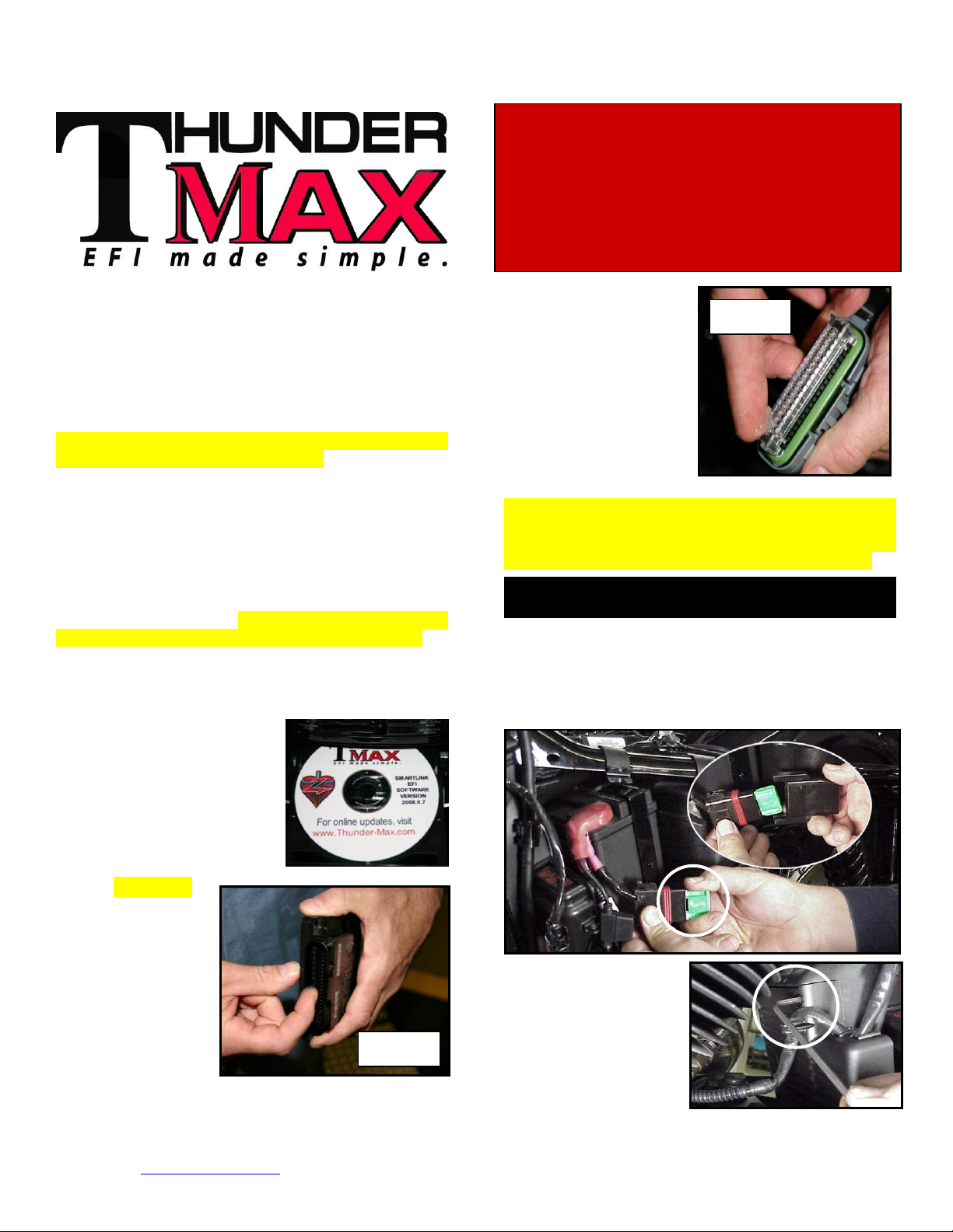
Step 2 All Models –
A packet of dielectric
grease is included
with your
ThunderMax. When
installing the ECM,
apply the provided
dielectric grease to
the inside lip of the
ThunderMax ECM
(Photo 1) and
www.Thunder-Max.com 309-385 Installation / Setup Guide V2012.06.28 Support@Thunder-Max.com
across the clear case on
the 36 pin ECM
connector (Photo 2).
Spread the grease across
all of the female terminal
openings, making sure
the grease penetrates
openings. This grease
will greatly improve vital
conductivity between the
ThunderMax and the 36
pin connector.
Remove any previously installed ancillary tuning
device including oxygen sensor eliminators that may
be plugged into the factory oxygen sensor harness.
Check battery cable terminals (clean and tighten).
XL-A: Remove the left side cover to expose the battery
and main fuse compartment. Remove the main fuse
cover, then the main fuse (Note: if equipped with
optional security system, turn on ignition switch before
you remove the fuse to avoid tripping alarm).
XL-B: Remove the
socket head screw and
slide the ECM cover
towards the left side of
the bike to remove it
(remove wires from
ECM caddy cover
channels).
2
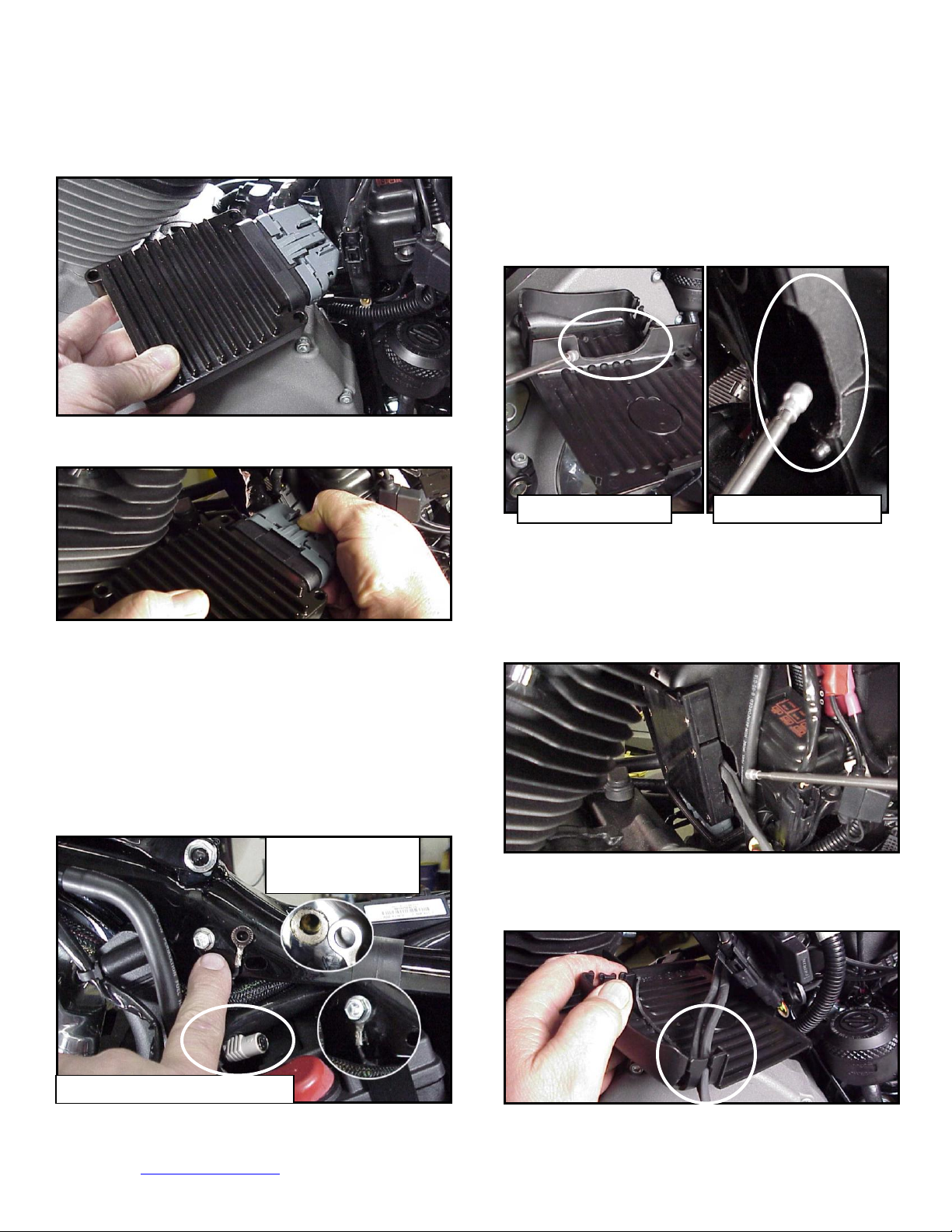
XL-C: Remove the stock ECM out of the caddy,
Cover Modification
Housing Modification
Scrape Paint
Before Installation
Communication Port Location
towards the primary side of the motorcycle. Lift tang on
the top of the caddy to help release the unit.
XL-F: With a Dremel® or suitable tool, remove material
from the outer caddy cover to accommodate the
AutoTune wiring as shown; make sure a generous
amount has been removed from this area to avoid
chaffing of the wiring. Grind a relief in the plastic caddy
to match the relief added to the caddy cover, providing
needed clearance for the oxygen sensor wires. The
outer caddy cover will shield the view of this area
XL-D: Fully depress connector tab and disconnect the
stock ECM from the 36 pin connector
XL-E: Install ThunderMax Pigtail connector # 309-324
to 36 pin harness connector per connector instructions.
Install ground wire to oil tank mounting bolt on left side of
the frame backbone above the battery as shown.
Carefully scrape paint from frame for a good ground
contact. Run the communication cable straight up inside
the caddy towards the left side of the motorcycle,
between the module area and the frame back bone,
coming out above the battery. Use a wire tie on the
connector to the main harness above the battery for
easy access under left side cover.
XL-G: Connect the pre-dielectric greased ThunderMax
ECM to the greased 36 pin harness plug, ensuring that
the harness plug weather seal does not get pinched
during assembly; firmly press the plug and ECM together
until latched completely. Place the ECM in position with
both sensor wires and AutoTune power cable exiting
through the relief in the ECM caddy as shown.
XL-H: Insert O
wires into cover channels along with
2
fuel pump wiring connector and reinstall the ECM caddy
cover.
www.Thunder-Max.com 309-385 Installation / Setup Guide V2012.06.28 Support@Thunder-Max.com
3
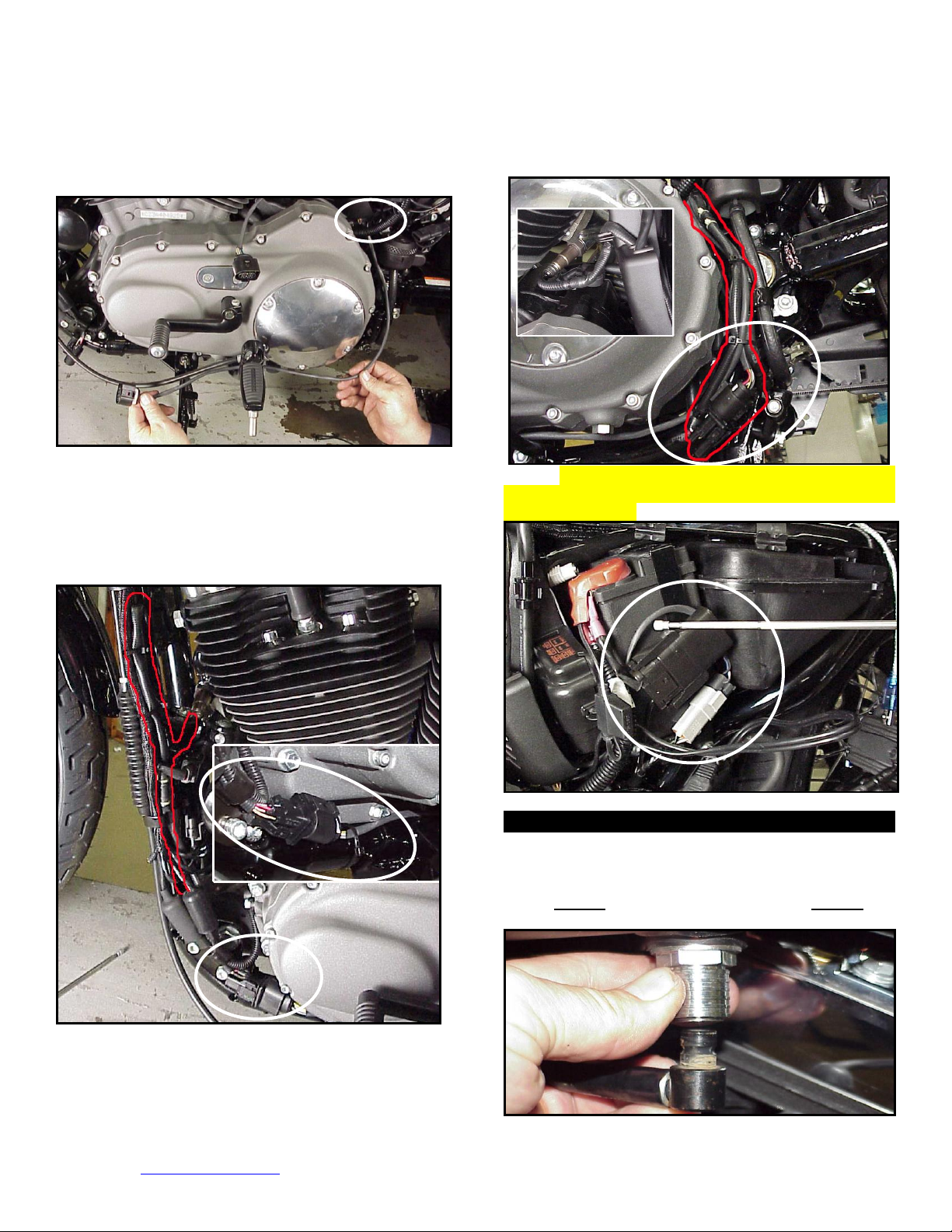
XL-I: Unplug and remove both factory O
Dyna® Models
sensors.
2
Route the front sensor lead behind the battery positive
cable, then between the primary cover and footpeg
mount to just in front of the kickstand mount.
Position the connector as shown; sensor harness will
double-back along frame tube to exhaust location.
Secure wires to brake line with wire ties.
XL-J: Install the front O
sensor into the exhaust pipe.
2
Plug sensor connector into the ECM sensor lead. Tie
the sensor wires to the frame with wire ties, positioning
the connector along the frame tube as shown. Extra
wire from the sensor must be routed up and back down
the frame tube and secured with the factory wire clamps
and wire ties. Carefully tie wires to avoid chaffing.
XL-L: Re-install main fuse. Route and plug AutoTune
power harness into 4-pin (gray) data port plug as shown.
Advance to Step 3.
FXD-A: Remove seat. Disconnect fuel line from fuel
tank by carefully pushing up the ribbed quick disconnect
ring on the tank fitting while gently pulling the fuel line
down. Loosen front fuel tank mounting bolt; remove rear
mounting bolt, prop up tank rear 4-5” with a wood block.
XL-K: Install the rear sensor into the exhaust pipe and
connect the sensor to the ECM harness. Route the rear
sensor harness loop behind battery positive cable and
along the brake line the rear of the primary housing.
www.Thunder-Max.com 309-385 Installation / Setup Guide V2012.06.28 Support@Thunder-Max.com

4
FXD-B: Remove left side cover to expose electrical
caddy. (1) Unplug and remove coil assembly from
caddy. (2) Slide diagnostic plug forward to remove from
caddy. (3) Remove ECM fuse (top left blue fuse; Note: if
equipped with optional security system, turn on ignition
switch before you remove the fuse to avoid tripping
alarm). (4) Remove 3 caddy mounting bolts.
FXD-E: Route front sensor along left frame backbone
under gas tank; position sensor plug just forward of
engine mount top link. Install supplied oxygen sensor in
front pipe and route harness up left frame tube to
connector as shown. Check that connector position
does not interfere with gas tank when in position before
securing harnesses with plastic wire ties.
FXD-C: Gently pull caddy from chassis far enough to
access the two stock ECM mounting bolts. Once ECM
is unbolted from caddy, depress tang on main 36-pin
ECM connector plug and remove ECM from plug. Install
pigtail harness to 36 pin connector as per included
instructions (do not install ground wire just yet).
FXD-D: ’06-’11 Models - unplug and remove factory
oxygen sensors from exhaust pipes. If you wish to cap
off the factory harnesses, inexpensive connector caps
can be purchased from any H-D® dealer (PN 72533-06).
Feed front & rear ThunderMax oxygen sensor harnesses
through ECM opening in caddy.
FXD-F: For the
rear cylinder, install
and connect the
oxygen sensor; coil
and tie the excess
harness and locate
it in the pocket
behind the ECM
caddy in front of the
frame backbone.
FXD-G: Install
ThunderMax ECM
to the caddy and
attach the caddy to
the chassis with the
two top frame bolts,
taking care not to
pinch any
harnesses in the
process. After
applying dielectric
grease (step 2),
connect the 36 pin
connector to the
ECM. Cut pigtail
ground wire to length, crimp on ring terminal and install
ground wire on center caddy mounting bolt between bolt
head and washer (1). Plug the closed loop module
into the 4-pin gray data link on the bike (2),
reconnect to caddy, then re-install the ECM fuse.
FXD-H: After checking that all harnesses are securely
tied down (away from any sharp edges that could chaff
or cut harnesses), re-install the ignition coil assembly,
gas tank, fuel line and seat. Advance to step 3.
www.Thunder-Max.com 309-385 Installation / Setup Guide V2012.06.28 Support@Thunder-Max.com

5
Rocker® and FXSTSSE2 Models
Oxygen Sensor Installation Notes
ST-A: Unplug and remove
the factory oxygen
sensors. Thread the
supplied front sensor up
from the bottom through
the gap between the
engine and kickstand
mount in front of inner
primary cover; install into
front pipe. Install sensor in
rear exhaust pipe; route
sensor lead under oil tank
to right rear of
transmission. Leave leads
loose for connection after
ECM installation.
ST-B: Locate and remove
the ECM fuse. Remove
rear fender assembly and
rear wheel to access ECM
mounting caddy. Remove
the plastic shield, then the
ECM caddy mounting
bolts.
ST-C: Remove the caddy
from the chassis, then remove
the factory ECM from the
caddy. Mount the T-Max ECM
using two mounting bolts.
ST-D: Install pigtail
communication harness to 36pin ECM plug as per included
instructions. After applying
dielectric grease (step 2),
connect the 36 pin connector
to the ECM. Re-install the
ECM caddy with the oxygen
sensor harnesses routed over
the top of the swingarm pivot
bolt; connect the rear sensors
and coil the excess harness
for the rear sensor (shown red) and tie it up under the
transmission housing, clear of the suspension and any
other moving parts.
ST-E: Route the front sensor lead along the right frame
rail, position connector as shown behind brake pedal; tie
harness to top of frame rail (avoid hot or moving parts).
ST-F: Connect and tie
front oxygen sensor.
Route 4-pin AutoTune
communication harness
and pigtail to the factory
grey data-port connector
located at the battery and
plug in the AutoTune
harness. Replace the ECM
fuse, position the pigtail for
convenient access and reinstall the rear wheel and
fender assembly; proceed to step 3.
The wide band sensors are longer than the factory
sensors. Installation of the wide band sensors into
factory headpipes presents no clearance problems,
however, some aftermarket pipes may require exhaust
pipe modification or sensor bung relocation for
interference-free installation. The sensors must mount
freely without contacting surrounding components. If
this is not possible, do not attempt to bend or
modify the sensor in any way as it is a sensitive
electronic component and will be damaged if you do.
Modify the pipe if required for clearance. Weld-in bungs
are available from many sources in straight or angled
versions if current bungs present clearance issues.
Step 3 Load a Base Map to your SmartLink software.
Selecting a base map for your ThunderMax is easy
thanks to the filtering system in the SmartLink software.
Open SmartLink; from the toolbar choose [EFI Maps]
[EFI Map Listings / Definitions]. You should first
update the Map Definitions file to ensure you have the
latest available maps. Close the [Base Map
Definitions] window, then click the [Check Internet For
Updates] button (requires internet connection; follow
prompts). After updating, select [Select BaseMap]..
www.Thunder-Max.com 309-385 Installation / Setup Guide V2012.06.28 Support@Thunder-Max.com
Available base maps will be shown (if the [Clear Filters]
button at the lower left of the screen is highlighted, click
it to clear filtered maps so all maps will be shown).

6
XL 883
2007-up
48400
XL 1200
2007-up
46000
DYNA®
2004-2005
40960
DYNA®
2006-2007
45900
DYNA®
2008-2009
42450
DYNA®
2010-2011
44750
ROCKER®
2008-2009
42450
ROCKER®
2010
44750
FXSTSSE2
2009
42450
Filter the maps to locate a base map that best matches
your application by placing your curser first over any
‘Engine Type’ that matches your engine and right-click it.
All maps that do not match your selection will be filtered
from the screen.
Second, place your curser
over the ‘Throttle’ column
and right click your match.
Third, right-click the
‘Exhaust’ type that closest
matches your application.
Fourth, right click the ‘Muffler’ column if further definition
of the exhaust system is required (depends on exhaust
application). Keep right-clicking the application columns
until you have located the best map match (in the case
of identical maps, choose the latest date). Highlight the
map you’ve chosen (left-click; blue bar indicates
selected map) and click [Close] button. This brings you
to the ‘Base Map Name Encoding’ page, from which you
can review the map
parameters. Click the [Load
BaseMap] button to load the
map into the software. Click
[Close] this page to view
the open map page.
Step 4 From the ‘Tuning Maps’ Tree, click the + sign
next to [Module Configuration], then double-click
‘Basic Settings’. The basic settings page opens.
Check to see if the [Speedo Cal] calibration setting
matches your year and model; if not, click the button,
enter the correct value as shown, then click [Close].
Speedometer Calibration Settings
Step 5 Now you are ready to
‘Link’ and ‘Write’ the map to the
ECM. Attach the communication
cable from your computer to the
ThunderMax pigtail harness,
making certain that the cable is
routed away from any part of the
motorcycle that generates heat.
Special Note for International Model Bikes with
Active Exhaust Enabled: If your bike is equipped with
a working Active Exhaust Valve, you must unplug the
active exhaust harness before linking to the module, as
the AEV circuitry conflicts with the communication
stream. You can re-connect the harness after unlinking.
If the stock exhaust has been changed, disregard this
step. ThunderMax does not support active exhaust
Step 6 To link to the module, turn the key switch to the
“Ignition” position, making certain the “RUN / OFF”
rocker switch (Kill Switch) on the handlebar controls is in
the “RUN” position. Select the “Link” Button in the
SmartLink software. The
button turns green to indicate a
successful link. Answer [No] to
the “Do you wish to READ the
module map now” question at
this time.
From the toolbar, click [File] [Write Module Maps and
Settings], answer OK to the overwrite message; the
transfer bar appears during the map load.
Step 7 Clear any active Diagnostic Code readings.
While linked, from the Tuning Tree select [Module
Configuration] [Diagnostic Codes], click [Clear].
www.Thunder-Max.com 309-385 Installation / Setup Guide V2012.06.28 Support@Thunder-Max.com

7
IMPORTANT STEP BEFORE STARTING
Step 10 Now select the IAC Stops vs. Engine
Next, ‘Initialize’ the ThunderMax ECM. Initializing
synchronizes ‘home’ positions for the TPS and IAC, and
is a required step any time battery power has been
interrupted or established to the ThunderMax ECM.
With the handlebar switch
in the ‘ON’ position, cycle
the key switch on and off
3 times, leaving the
ignition on for 30
seconds, then off for 30
seconds, each cycle. DO
NOT start the engine or
move the throttle during this
process. After 3 on/off cycles, make certain that the
motorcycle is in neutral and start the bike 2 times, letting
it settle at idle for 10 seconds; the idle should be smooth
and steady. Some engines may require several on/off
engine starts to initialize properly. This initialization
process must be performed any time battery power
is interrupted to the module (after battery
servicing/winterization, etc). After initialization, shut off
the engine, but stay linked for step 8.
Step 8 Before restarting the engine (while linked) from
toolbar click [Monitoring] [Show Gauges]. The
“Engine Speed”, “Engine Head Temp”, “IAC Position”,
“AFR Front”, AFR Rear” and “AFR Target” gauges are
automatically formatted and are shown on the screen.
Step 9 Select the “Monitor” button to active the gauges.
It is located beside the “Link” button and will turn green
when the monitor gauge functions are live. The gauges
will be displayed if they were not already on the screen.
Temperature page from “IAC Curves” menu within the
tuning tree. Strike the spacebar to show the actual
values of the tuning block (use left/right arrow keys to
move the block marker). Make certain that the
motorcycle is in neutral and the engine is cold, and then
start the engine. Once the engine idle is stable after 1520 seconds, select the “IAC-Auto” button (Idle Air
Control Auto Adjustment). Allow the “IAC-Auto” function
to run at idle until the engine head temperature reaches
275 degrees. After reaching temperature of 275
degrees, the “IAC-Auto” function automatically shuts off.
You can terminate this function at any time, and re-run it
at a later time if you wish.
Step 11 Unlink the SmartLink software from the ECM,
turn off the ignition switch and remove the
communication cable from the pigtail connector. Use the
‘Save As’ command to create a folder and save the map
to your hard drive. The motorcycle is now ready to be
ridden. Several riding sessions that allow the engine to
reach normal operating temperature should be
completed. During this process, the IAC virtual stops will
automatically be adjusted to the IAC target values set
within the map’s basic settings. This feature
automatically adjusts how the engine comes back to the
specified idle speed. If the IAC stops are set too low, the
engine will dip below the specified idle speed during
certain transient conditions. If the IAC stops are above
the IAC position, the engine will idle above the idle rpm
specified in the idle speed vs. engine temperature page.
If it is determined that these automatic adjustments have
not resulted in satisfactory operation of the engine,
consult the SmartLink Manual (available under the Help
section of the toolbar), Section 3 (Tuning the
ThunderMax ECM) for further adjustment procedures.
TIPS AND GENERAL INFORMATION
Several support features are located under the [Help] menu:
o A comprehensive tuning manual
o Links to allow transmission of module and map data via E-mail directly to ThunderMax support
o Links to allow transmission of monitor logs (recorded riding sessions) via E-mail directly to ThunderMax
support (see video link page 8)
o Links to Thunder-Max.com web site for support documents and videos
‘08-‘10 Softail® and ’09-’11 Dyna® models with Distance To Empty readout in the speedometer may lose this
function upon battery or main fuse disconnection during installation and future services involving electrical power
interruption. To restore this feature follow the instructions located under [Help] in the SmartLink Software toolbar.
www.Thunder-Max.com 309-385 Installation / Setup Guide V2012.06.28 Support@Thunder-Max.com

8
System Updates are available through SmartLink with an internet connection. Software, Firmware and Map
updates can be downloaded; dealers, tuners and end users should check frequently for updates.
TMax Control Center provides a snapshot of AutoTuned fuel flow adjustments, RPM time logs in increments of
100 RPM’s, engine temperature logs and diagnostic codes. Valuable information about the condition of your tune
and how you ride. AutoMap, located within the TMax Control Center, feature creates a custom base map based
on AutoTuned fuel flow adjustments. Create a custom base map with just a few clicks!
International (non-US) model notes – ThunderMax does not support active intake/exhaust functions or Jiffy
stand safety switch.
When the SmartLink program is opened, it will automatically retrieve and open the last map that was open.
Any time you link to your motorcycle: Read the map that is installed in the ThunderMax ECM by selecting
[File] then [Read Module Maps and Settings] on the SmartLink toolbar. This will synchronize the map file
loaded into the ThunderMax ECM with the SmartLink software.
2007-up 6-Speed Big Twin models: There are two settings in the [Module Configuration] [Basic Settings] page
that should to be set to the following to enable the 6th gear indicator light to function:
Final drive ratio: 06-07 Dyna® [84], ’07 FL, ’07-’10 Softail®, ’08-’11Dyna® [87] Gear 6 Min TPS (all) [40]
AFR Correction vs. Engine Temperature page is used to adjust warm-up AFR’s. If the engine requires more
fuel during warm-up (start to 200°), use this function to adjust. See SmartLink Tuning Manual for procedures.
AFR vs. Engine Temperature - During warm-up, the AFR on both cylinders will show richer than the target AFR
at operating temperatures; this is a normal part of the warm-up map. No permanent changes to AFR targets and
adjustments are made below 200 degrees. See SmartLink Tuning Manual for applications and procedures.
Air/Fuel-TPS @ RPM These pages reflect desired targets of AFR to throttle position at every 256 RPM.
Example: if you desire a leaner mixture for added fuel economy then you can easily enhance multi-tiered AFR
targets at specific throttle positions and RPM’s that will be learned during riding sessions. When these pages are
open, you can view the target AFR by clicking on a dot and tapping the space bar to view the target at a specific
throttle position for that RPM. Use arrow keys to raise/lower targets.
Interrupting 12v power to the module (battery service/replacement) requires system to be re-initialized (Step 7).
Check battery terminal tightness as part of routine service (like during oil changes); avoid stacking accessory
power leads onto main battery cables. If equipped with dual battery post ports, connect accessories separately.
When a new map is installed any existing learned fuel and IAC adjustments need to be cleared (Map Editing,
clear x2). Linking and editing an existing map within the module does not require above steps.
System Updates are available through your software with an internet connection [Configure] [SmartLink
Update]. Software, Firmware and Map updates can be downloaded; check frequently for updates.
In-Tank Fuel Filters should be inspected as a part of routine maintenance. The filter is small and one bad load
of fuel can compromise it. The factory recommended service interval is 25K miles.
Fuel Pressure Should Be Checked during periodic service; this is also the first thing to check should you
experience sudden or gradual decreasing performance. For any EFI system to operate properly, your fuel system
should build and maintain 55-62 PSI of fuel pressure; your dealer can perform this simple test quickly.
Save your edited maps to your hard drive using the [Save As] command. Document the changes in [Map Notes]
located under [EFI Maps on the toolbar. These notes are stored with the saved map; remember to edit them
when making changes for future reference.
Oxygen Sensor Care: Items that can damage or shorten the life of your sensors:
Leaded fuel – Race fuel Oil deposits from oil consumption problems
Excessive moisture exposure Excessive (extreme) heat
There is no warranty on sensors. Replacement P/N is 309-355.
For additional video instructions go to:
http://www.youtube.com/user/ThunderMaxV
www.Thunder-Max.com 309-385 Installation / Setup Guide V2012.06.28 Support@Thunder-Max.com
 Loading...