


PN-309-385
www.Thunder-Max.com 309-385 Installation / Setup Guide V2012.06.28 Support@Thunder-Max.com
1
Part # 309-385 for
2010-2012 XL Models
2004-2011 Dyna® Models
2008-2010 Softail® Rocker Models
2009 CVO Springer FXSTSSE
2
Thank you for purchasing a ThunderMax ECM!
Please read through the following instructions before
beginning the installation procedure. Following these
instructions will ensure that the ECM is installed and
setup properly for optimal results. If you have any
problems or questions, please refer to the SmartLink
Tuning .pdf Manual, included on the CD (Help Menu)
with this package. The cable included with your
ThunderMax requires a serial port on your computer for
communication with the ThunderMax. If you do not have
a serial port on your computer, you will need to use a
USB to Serial converter. Record serial number NOW
on your warranty card, and here for your records!
ECM Serial # TMFM____________________________
AutoTune Serial # TMAT________________________
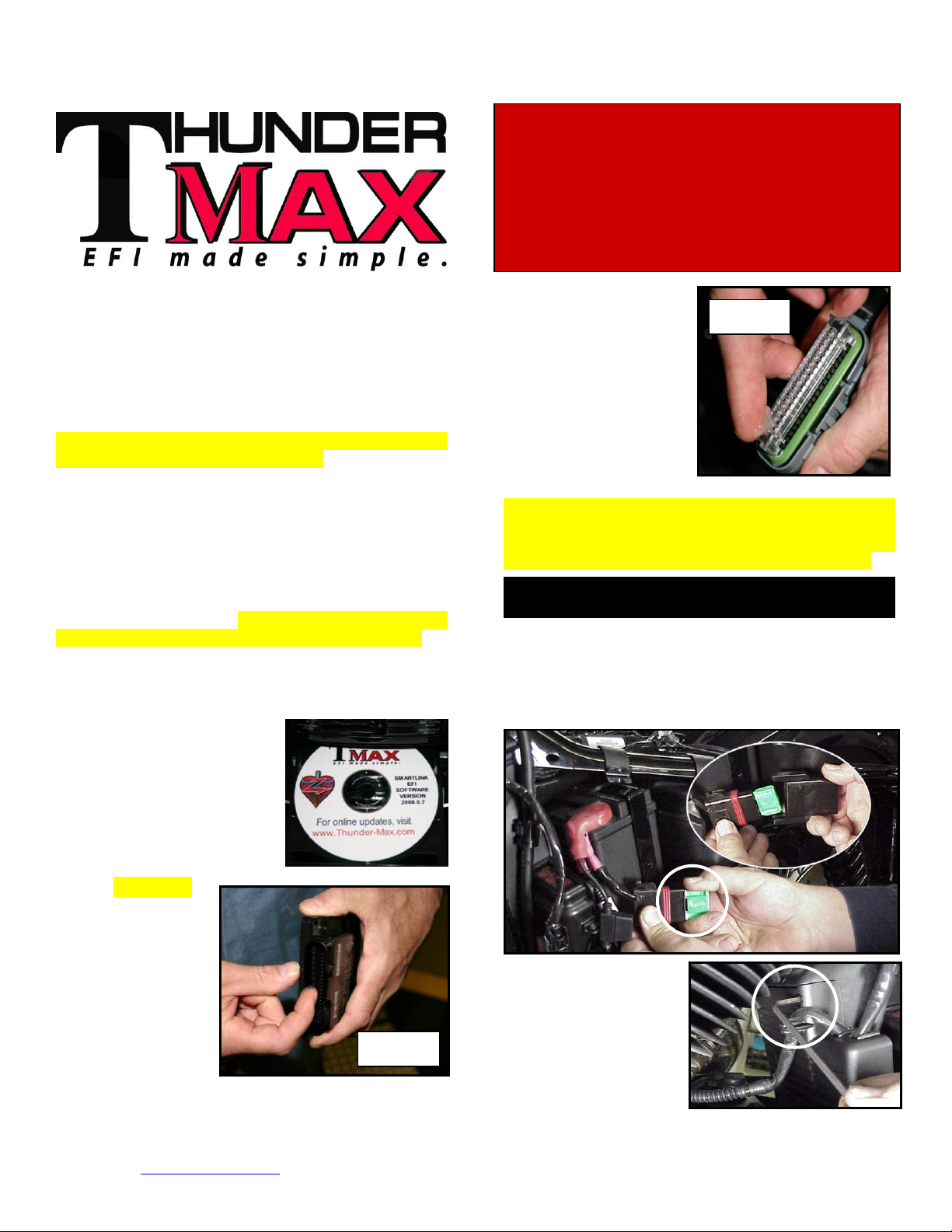
Step 1 Insert the SmartLink
CD into your computer.
SmartLink will automatically
open the InstallShield Wizard
when the computer finds the
CD-Rom. Follow the
instructions and install the
software on your computer.
Step 2 All Models –
A packet of dielectric
grease is included
with your
ThunderMax. When
installing the ECM,
apply the provided
dielectric grease to
the inside lip of the
ThunderMax ECM
(Photo 1) and
across the clear case on
the 36 pin ECM
connector (Photo 2).
Spread the grease across
all of the female terminal
openings, making sure
the grease penetrates
openings. This grease
will greatly improve vital
conductivity between the
ThunderMax and the 36
pin connector.
Remove any previously installed ancillary tuning
device including oxygen sensor eliminators that may
be plugged into the factory oxygen sensor harness.
Check battery cable terminals (clean and tighten).
XL Sportster® Models
(Skip ahead for Dyna® or Rocker® Models)
XL-A: Remove the left side cover to expose the battery
and main fuse compartment. Remove the main fuse
cover, then the main fuse (Note: if equipped with
optional security system, turn on ignition switch before
you remove the fuse to avoid tripping alarm).
XL-B: Remove the
socket head screw and
slide the ECM cover
towards the left side of
the bike to remove it
(remove wires from
ECM caddy cover
channels).
Installation / Setup Guide
Please Note: This product is Legal in California
only for racing vehicles which may never be used
upon a highway. The user shall determine suitability of the
product for his or her use. Installation and use on a pollution-
controlled vehicle constitutes tampering under the U.S. EPA
guidelines and can lead to substantial fines. Review your
application and check your local laws before installing.
Photo 1
Photo 2
www.Thunder-Max.com 309-385 Installation / Setup Guide V2012.06.28 Support@Thunder-Max.com
2
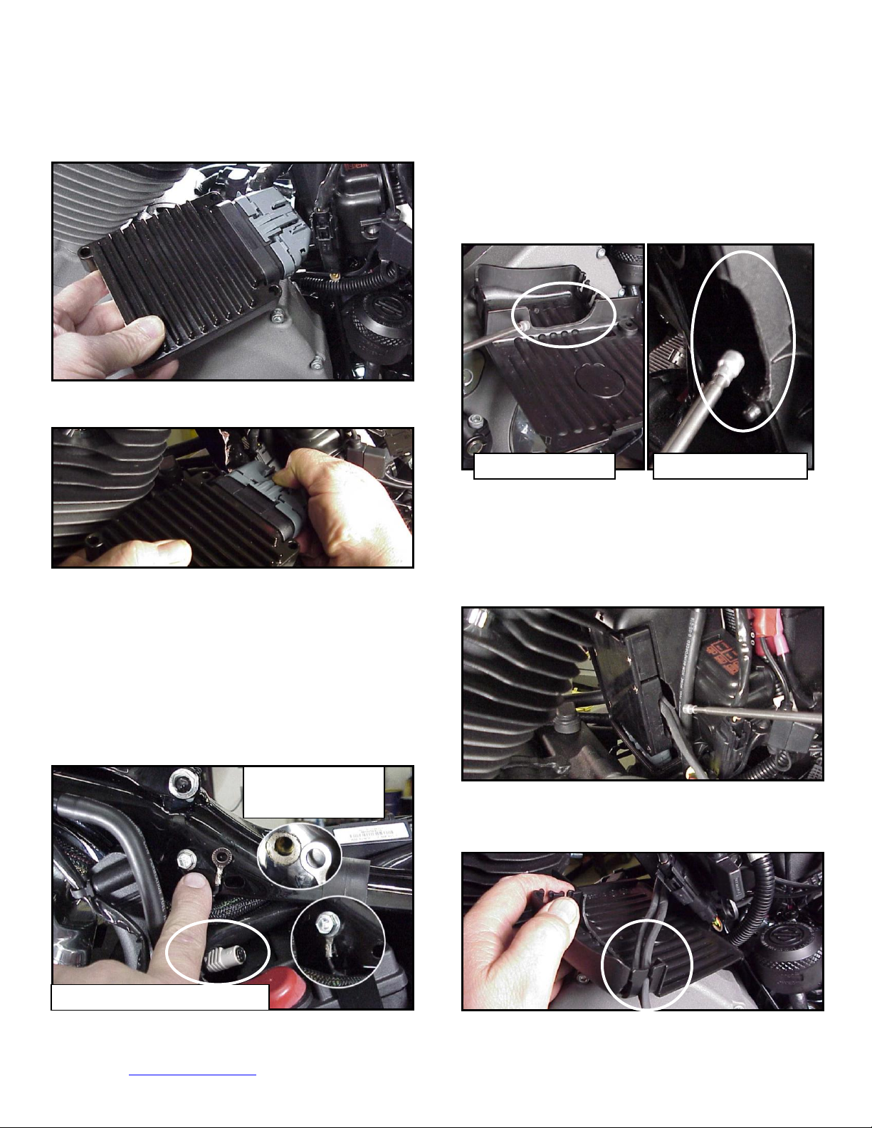
XL-C: Remove the stock ECM out of the caddy,
towards the primary side of the motorcycle. Lift tang on
the top of the caddy to help release the unit.
XL-D: Fully depress connector tab and disconnect the
stock ECM from the 36 pin connector
XL-E: Install ThunderMax Pigtail connector # 309-324
to 36 pin harness connector per connector instructions.
Install ground wire to oil tank mounting bolt on left side of
the frame backbone above the battery as shown.
Carefully scrape paint from frame for a good ground
contact. Run the communication cable straight up inside
the caddy towards the left side of the motorcycle,
between the module area and the frame back bone,
coming out above the battery. Use a wire tie on the
connector to the main harness above the battery for
easy access under left side cover.
XL-F: With a Dremel® or suitable tool, remove material
from the outer caddy cover to accommodate the
AutoTune wiring as shown; make sure a generous
amount has been removed from this area to avoid
chaffing of the wiring. Grind a relief in the plastic caddy
to match the relief added to the caddy cover, providing
needed clearance for the oxygen sensor wires. The
outer caddy cover will shield the view of this area
XL-G: Connect the pre-dielectric greased ThunderMax
ECM to the greased 36 pin harness plug, ensuring that
the harness plug weather seal does not get pinched
during assembly; firmly press the plug and ECM together
until latched completely. Place the ECM in position with
both sensor wires and AutoTune power cable exiting
through the relief in the ECM caddy as shown.
XL-H: Insert O
2
wires into cover channels along with
fuel pump wiring connector and reinstall the ECM caddy
cover.
Cover Modification
Housing Modification
Scrape Paint
Before Installation
Communication Port Location
www.Thunder-Max.com 309-385 Installation / Setup Guide V2012.06.28 Support@Thunder-Max.com
3
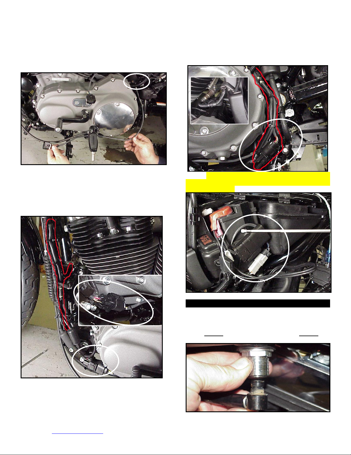
XL-I: Unplug and remove both factory O
2
sensors.
Route the front sensor lead behind the battery positive
cable, then between the primary cover and footpeg
mount to just in front of the kickstand mount.
XL-J: Install the front O
2
sensor into the exhaust pipe.
Plug sensor connector into the ECM sensor lead. Tie
the sensor wires to the frame with wire ties, positioning
the connector along the frame tube as shown. Extra
wire from the sensor must be routed up and back down
the frame tube and secured with the factory wire clamps
and wire ties. Carefully tie wires to avoid chaffing.
XL-K: Install the rear sensor into the exhaust pipe and
connect the sensor to the ECM harness. Route the rear
sensor harness loop behind battery positive cable and
along the brake line the rear of the primary housing.
Position the connector as shown; sensor harness will
double-back along frame tube to exhaust location.
Secure wires to brake line with wire ties.
XL-L: Re-install main fuse. Route and plug AutoTune
power harness into 4-pin (gray) data port plug as shown.
Advance to Step 3.
Dyna® Models
FXD-A: Remove seat. Disconnect fuel line from fuel
tank by carefully pushing up the ribbed quick disconnect
ring on the tank fitting while gently pulling the fuel line
down. Loosen front fuel tank mounting bolt; remove rear
mounting bolt, prop up tank rear 4-5” with a wood block.
 Loading...