

Page 1
1
Installation / Setup Guide
Please Note: This product is Legal in California
only for racing vehicles which may never be used
upon a highway. The user shall determine suitability of the
product for his or her use. Installation and use on a pollution-
controlled vehicle constitutes tampering under the U.S. EPA
guidelines and can lead to substantial fines. Review your
application and check your local laws before installing.
New! Video Instructions Now Available on You Tube – Smart Phone Users See Back Page
#309-362, 2010-13 TBW Touring Models
Thank you for purchasing a ThunderMax ECM!
Please read through the following instructions
before beginning the installation procedure.
Following these instructions will ensure that the ECM is
installed and setup properly for optimal results. If you
have any problems or questions, please refer to the
TMax Tuner .pdf Manual, included on the CD (Help
Menu) with this package. Record serial number NOW
on your warranty card, and below for your records!
Serial # TMWM___________________
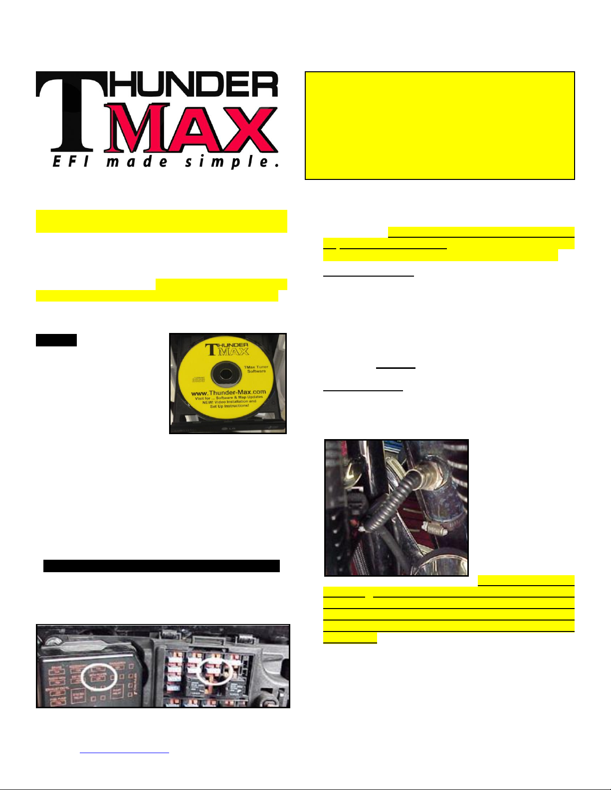
Step 1: 1: Insert the TMax
Tuner CD into your
computer. TMax Tuner will
automatically open the
InstallShield Wizard when
the computer finds the CDRom. Follow the
instructions and install the
software on your computer.
After installing and opening the software the first time,
you will be prompted to install the driver for the USB
connection (see page 4). The TMax Tuner software
package is designed to run on personal computers using
Microsoft® Windows 2000™, Windows XP™, Windows
Vista™ and Windows 7 & 8 operating systems. The
computer system must have an adequate amount of free
space on the hard drive for proper operation. TMax
Tuner is approximately 140MB when installed. TMax
Tuner is not supported by any other operating systems.
Step 2 : Module Installation - Touring Models
FL-A: Install the ThunderMax ECM. Remove seat and
both side covers. Push up on the bottom of the fuse box
cover to remove the cover (located on the left side of the
bike), then remove the ECM fuse from the fuse box.
www.Thunder-Max.com 309-362 Installation / Setup Guide V2013.10.15 TmaxSupport@Thunder-Max.com
FL-B: Remove the stock narrow band sensors from the
exhaust pipe. Special Note – If you have previously
installed another tuning device such as a Power
Commander, be sure to remove the device and any
“O
Sensor Eliminators” that may have been
2
installed at the sensor harness plugs at that time!
2008-2009 models: 18mm sensors are located at the
top of the head pipe; supplied 18mm wide-band sensors
will replace the stock narrow band sensors. Some stock
2008 model rear bung location may cause interference
with the transmission lid when using the longer
ThunderMax oxygen sensor. If this is the case, crease
the pipe next to the bung to change the angle of the
sensor for clearance, or relocate the bung for proper
clearance. DO NOT pull or pry on the sensor to gain
clearance—the sensor will be damaged if you do!
2010-13 models: If retaining factory catalyst-equipped
headpipes, 18mm bungs will need to be added to the
headpipes. Bungs should be located no more than 3-4”
from the head pipe connection (for ideal location, refer to
the factory location on 2009 models). Weld-in bungs are
available from many
sources in straight or
angled designs. See
Video on adding new
bungs on the web at
ThunderMaxAV) or
through your smart
phone by scanning
the QR code on page
8.
Stock 2010-2013
12mm O2 sensors are located downstream on the
factory header pipes, between the engine and
transmission; unplug and remove them as they will
affect your ThunderMax system performance if left
plugged in. Stock sensor connectors are located under
the bike's right side cover (black and gray plugs). 12 mm
pipe bung O2 caps are available from many sources.
FL-C: Install supplied wide-band sensors into the pipes;
route the front sensor along the cross brace on the
frame in front of the engine and down the lower frame
rail on the right side of the motorcycle.
YouTube.com
(search
Page 2
2
Depress button
Rotate locking bar fully
towards rear of bike until
index pin reaches notch
FL-D:. Route the
rear sensor lead
between transmission
top cover and the
starter, then towards
the ABS caddy
located under the
right side cover.
Place the sensor
connector under the
ABS caddy.
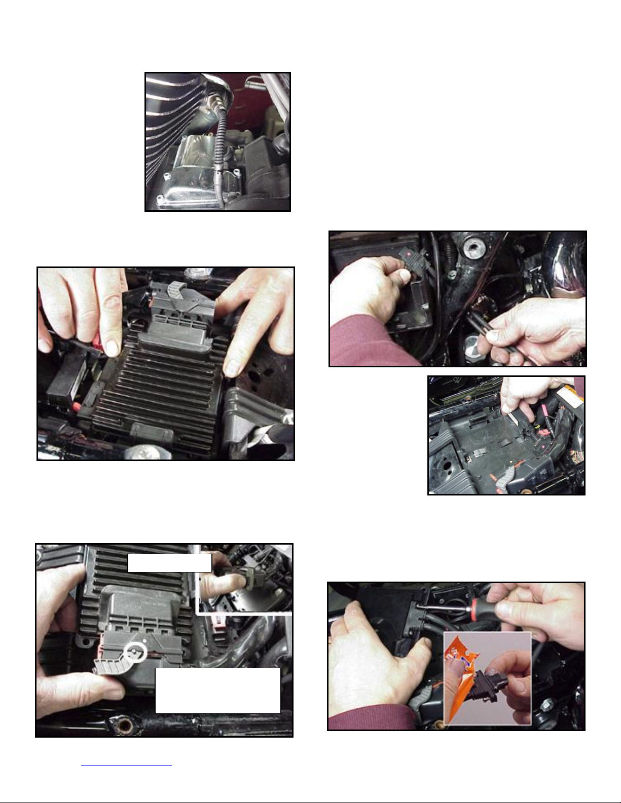
FL-E: Remove factory ECM from the caddy by
spreading the plastic caddy latches at the sides of the
ECM. Lift the ECM up and to the right to release it from
the caddy.
FL-F: Disconnect the ECM from the connector as per
the following procedure:
Depress button on socket housing of the connector;
rotate locking bar until it reaches the full rearward
position (the index pin on locking bar will engage the
rear notch in the socket housing).
The connector internal latches are not fully disengaged
until the locking bar on the connector is seated to the full
rearward position to complete removal of the connector.
If you force the socket housing with latches partially
engaged, it will result in damaging the connector. Once
index pin is fully seated, with steady yet careful attention,
pull apart the connector from the factory ECM and
remove it from the motorcycle.
FL-G: With the factory ECM removed, route the
AutoTune harness thru the opening on right side of the
frame below the down tube for the seat, towards the
ECM caddy.
FL-H:. If equipped
with factory alarm,
detach alarm
antenna from ECM
caddy clip by lifting
slightly and sliding
to the right of bike
(do not disconnect).
FL-I: Locate the package of dielectric grease included
with communication cable. Spread a small amount of
grease on the AutoTune harness plug inboard of the
mounting flange to allow the plug to easily slide into the
ThunderMax ECM, with ThunderMax logo on harness
plug facing up. Attach with screws provided.
FL-J: Install main harness connector to ThunderMax
www.Thunder-Max.com 309-362 Installation / Setup Guide V2013.10.15 TmaxSupport@Thunder-Max.com
Page 3
3
Fully closed position:
Index pin engaged
with forward notch
Sliding colored cam locks
in fully open position
towards rear of bike
Sliding colored cam locks
in fully closed position
towards front of bike
Fully open position:
Index pin engaged
with rearward notch
ECM. Before installing connector, lightly spread some
dielectric grease on harness connector terminals, and on
the inside lip of the connector port opening of the ECM
to allow the rubber weather seal in the connector plug to
slide into place without binding. Apply a dab of grease
to the (2) upper and lower locating pins on the
ThunderMax housing as well (arrows). See ‘Tips’ on
page 7 for additional dielectric grease instructions.
Before connecting, verify that the locking bar is in the
fully open, rearward position (locking bar index pin is
fully engaged with rear notch in the socket housing).
Important Note: Pin and socket housing of the
connector must be fully engaged before you rotate the
locking bar to the forward position. Forcing the locking
bar forward before the connector is fully engaged will
damage the connector and/or the ECM
FL-K: Place the ThunderMax ECM into the ECM caddy.
If equipped, position alarm antenna as shown.
FL-L: Connect the oxygen sensor harnesses to the
AutoTune harness. Carefully wire tie the leads to the
motorcycle. Take extra care to ensure harness and
sensor leads are safe from rubbing or chaffing on the
motorcycle. Use all supplied wire ties; add extra ties if
needed to properly secure wiring on your installation.
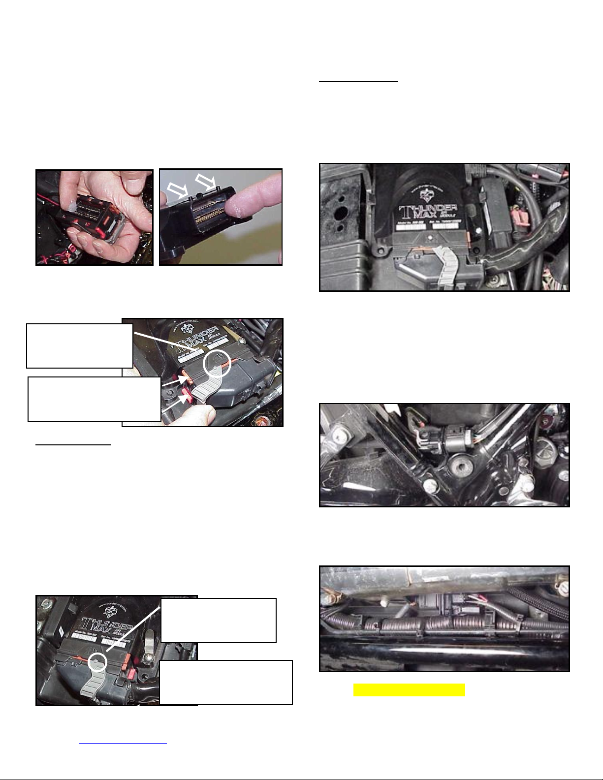
FL-M: Position the rear connector under the ABS caddy
and attach with wire ties provided as shown.
Important Note: If socket housing with grounding pin
are not properly aligned during connector installation
damage to the grounding pin will likely occur, which will
require you to return the ThunderMax ECM for repair to
the damaged pin.
Rotate the locking bar forward to engage the connector.
Observe that the colored cam locks are moving with the
locking bar; proper execution will show both colored cam
locks visible in equal amounts on the forward-facing side
of the connector when the locking bar is in its fully
seated position with the button lock engaged, as in the
image below (do not force the locking bar). Index pin
will engage front notch in socket housing.
FL-N: Position front connector above lower frame rail
between engine and transmission. Attach to existing
harness with provided wire ties. Inspect all wiring to
make sure it is clear of moving parts and excessive heat.
FL-O: Re-install the ECM fuse and replace the side
covers.
www.Thunder-Max.com 309-362 Installation / Setup Guide V2013.10.15 TmaxSupport@Thunder-Max.com
Page 4

4
If you purchased a pre-mapp ed system, you
may skip steps 3-6; proceed to Initializing (step 7).
Step 3: Choosing and Installing a Map
Now it’s time to turn your
attention back to your
computer. Open your TMax
Tuner software. There is no
need to link to the module at
this time. To ensure you are
working with the latest version
of TMax Tuner software and
have the most up-to-date
selection of base maps, it is
suggested that you establish an
Internet connection and click
[Configure] on the tool bar,
then [TMaxI Software Update] and follow the prompts.
After uploading new
software (if found), next
click [EFI Maps] [EFI
Map Listings (Throttle
By Wire)], double-click
any map; when the Base
Map Name Encoding
window appears, click the [Check Internet For
Updates] button and follow the prompts. Close window
after updating.
Loading Interface Drivers and VIN Number_
Next, the TMax Tuner software for the ThunderMax
Throttle By Wire EFI systems contains the correct
drivers required for USB interface with the ECM.
Connect the USB cable to the specific port on your PC
that the driver will be configured to, and the ThunderMax
ECM, located under the
retainer plate (loosen
retainer screw, rotate
retainer plate and open
rubber weather seal).
Open the TMax Tuner
software and turn the
bike’s ignition and
handlebar switches to the
on/run positions. Follow
the prompt instructions for
installing the driver.
Next, go to the menu bar and select [Tuning Maps]
[+Module Configuration] [Module Service Data].
Under the Module Information tab, click [Edit VIN/SRN]
and enter your motorcycle’s serial number (CAPITAL
LETTERS ONLY), click [OK] then [Close]. Turn off
ignition when finished. Once your software, map
databases and USB driver are verified as up-to-date, go
to selecting and loading your base map.
Selecting A Base Map File from the Database
The TMaxII Tuner EFI Map Database will help you
chose a Base Map for your application. To open the Map
Database, select from
the toolbar [EFI Maps]
[EFI Map Listings
(Throttle By Wire)].
Available base maps
will be shown (if the
[Show All Maps]
button at the lower left
of the screen is
highlighted, click it to
clear any filtered maps so all maps will be shown).
You will now be able to select the closest Base Map for
your engine combination. Please read the following
section on Key Elements, this will help you quickly
narrow down the selection of available Base Maps and
find the right one for your application.
The reason for selecting a Base Map by “Key Elements”
Base Map “Key Elements”
is to find the closest Base Map match available for your
combination, identified by the most critical components.
These include:
Engine Size. A correct match to the engine’s stroke is
more important than an exact match of engine
displacement. Stroke and cam timing influence engine
pumping pressures. The correct shape of spark curves
in the base map will be best matched by engine stroke.
Throttle Body / Injector Size. Choose the throttle body
and injectors being used for your application (most
applications will be “stock” unless performance parts
have been installed).
Camshaft. Many popular short duration aftermarket
cams (less than 240° intake duration) perform well when
using a stock-cam base map. With broader timing cams
(more than 240° intake duration) you may find that
choosing a base map calibration developed for an
aftermarket cam to be a better choice.
Exhaust System Design. There is no need for concern
if an exact brand match does not appear in the Base
Map library. Simply select the Base Map with the
closest style of exhaust system (Slip-ons, 2:1, True
www.Thunder-Max.com 309-362 Installation / Setup Guide V2013.10.15 TmaxSupport@Thunder-Max.com
Page 5

5
Duals). Choosing the closest style will yield excellent
results. Group your exhaust system in one of the
following three categories:
Factory Head Pipe with Crossover: Dual exhaust
systems with a cross over pipe that connects the front
and rear exhaust pipes (includes 'X' pipes). Typically
used with accessory slip-on mufflers. Bikes with
catalyst-equipped mufflers or headpipes require
maps designed for use with catalyst-equipped
systems or damage to the catalyst can result.
ThunderMax maps for use with 96, 103 and 110”
internally
2 into 1: Both head pipes converge into one collector.
stock engines are
catalyst-safe
maps.
(True) Dual Exhaust: 100% separate exhaust pipes.
ThunderMax’s AutoTune system allows you to choose a
Base Map that isn’t an exact match of components and
still have excellent results. Even if your combination isn’t
listed, select the closest Map match and let the
AutoTune create your custom Base Map while you ride.
The closer match that the Base Map is to your
combination, the faster the system will achieve the
desired AFR Targets. This simply means less time to
establish and maintain a great tune. Once you have
allowed the system to establish custom AFR fuel-flow
adjustments, you can use the AutoMap function to
create an all-new Base Map based upon the Auto Tuned
learned adjustments. To use the AutoMap feature, see
the tuning manual for the procedure on how to create
your custom base map using AutoMap.
Base Map File Browsing / Selection
With your Base Map Definitions window open, you may
begin narrowing down the list of maps for your
application. To sort the map files by a particular key
element, left-click on the column heading to arrange the
column in alpha/numeric order. All of the columns can
be sorted in this manner for filtering purposes. Filter the
maps to identify the base map that best matches your
application by following these easy steps:
First (in order of importance) place your curser over the
‘Family’ heading and left-click to change the sort order
of that column. Scroll down the list and place your
mouse pointer over you bike’s family match and rightclick to filter out no-match applications from the list.
Second, right-click the engine size under ‘Engine Type’
that matches your engine. All maps that do not match
your selection will be filtered from the screen.
Third, place your curser over the ‘Throttle’ column and
right click your match (injector size is more important
than throttle body size if you have to choose).
Fourth, right-click the ‘Cam’ that closest matches your
application.
Fifth, right click the ‘Exhaust’ that closest matches your
application.
Keep right-clicking the application columns until you
have located the best map match (in the case of
identical maps, choose the latest date). Highlight the
map you’ve chosen (left-click; blue bar indicates
selected map) and click the [Close] button.
Step 4: This brings you to the ‘Base Map Name
Encoding’ page, from which you can review the map
parameters. Once verified, click the [Load BaseMap]
button to load the map into the software.
Tip - After any filtering, notice that the [Show All Maps]
button at the bottom left is now selectable. At any time if
you want to return to the complete library listing, left-click
the [Show All Maps] button and you will start over with
all Base Map Files in the library displayed.
www.Thunder-Max.com 309-362 Installation / Setup Guide V2013.10.15 TmaxSupport@Thunder-Max.com
Note - If you’re still unsure of which Base Map to select,
please email the specifications of your Key Elements to
Support@Thunder-Max.com. Please title the email
“Base Map Selection” for a faster response.
Page 6

6
IMPORTANT STEP BEFORE STARTING
Step 5: Next, go to the [Tuning Maps] Tree and click
the [+] sign next to [Module Configuration] to reveal
the [Basic Settings] command. Open the Basic
Settings window and click the [Speedo Cal] button (list
window appears).
Verify that the Speedometer Calibration is set for your
year motorcycle based on the chart. If it is, click
[Cancel]; if it is not, enter the correct value and click
[OK], then [Close] the Basic Settings window.
Step 6: Now that the Base Map is loaded into the
TMaxII Tuner software; you must ‘Write’ (transfer)
the Base Map to your ThunderMax ECM. With the
communication cable connected, linking to the module is
now automatically performed with the TMaxII Tuner
software when the handle bar and key switch are in the
on/run positions. Turn the ignition switch on; the red
[Link] button will turn green to indicate a successful link.
Once linked, from the toolbar click [File] [Write Module
Maps and Settings], answer [OK] to the 'To Running
Position' command in the 'Module Configuration Write
Options' window that opens; the transfer bar then
appears during the map load. Once the Base Map has
been written to the module, clear any active Diagnostic
Code readings and Learned Fuel Adjustments that may
have been created during the live module testing
session that each ThunderMax module must pass.
While linked, from the Tuning Tree select [Module
Configuration] [Diagnostic Codes]. When the
Diagnostic Codes window appears, select [Clear
Diagnostic Codes]. After completing this step, proceed
to [Map Editing] menu on the tool bar and select [Clear
“Learned Fuel
Adjustments (CLP
OFFSET)”]. These
steps ensure you
will be starting with
a “clean slate” Base
Map.
This step is required for new module installation, or
when interruption of 12v power to the ECM takes place.
Example: battery change, removal of maxi fuse, etc.
Turn the ignition switch on with the handlebar rocker
switch to the run position for 20 seconds, uninterrupted.
Cycle the ignition switch off and on, then start the
engine. Let the motorcycle idle on its own for 15
seconds. Cycle the ignition off and restart the
motorcycle; normal idle speed should be attained
depending on engine temperature. Warm-up cycle will
have slightly elevated idle speed (approximately 1200
rpm) until engine reaches operating temperature. To
disconnect from the PC, click the Unlink button (turns to
red), remove the
USB cable and snap
the weather seal
plug into the USB
cable port. Position
the retainer plate
over the weather
seal and tighten the
retainer plate screw.
Congratulations! You have successfully installed and
set up your ThunderMax ECM. Now it’s time to ride the
bike and let ThunderMax optimize your EFI system!
Several riding sessions that allow the engine to reach
normal operating temperature should be completed with
as much variation in terrain and RPM as possible.
Your ThunderMax customizes your map based on your
engine, ambient conditions and your riding habits. Once
several sessions have been logged, link to your
ThunderMax and select [TMax Module Control Center]
for an automatic analysis of the adjustments that have
been made, and follow prompts for further action if more
optimization is suggested.
Need Help?
We have included many
easy-to-use features for
supporting and enriching
your ThunderMax
experience. A full tuning
manual, links to online
support documents and
sites as well as the ability
for you to easily attach a
map or recorded engine
monitoring log to an
email directly to our
support department are
found here.
Step 7: Initialization Procedure
www.Thunder-Max.com 309-362 Installation / Setup Guide V2013.10.15 TmaxSupport@Thunder-Max.com
Page 7

7
TIPS AND GENERAL INFORMATION
Several support features are located under the [Help]
menu:
A comprehensive tuning manual
Links to allow transmission of module and map
data via E-mail directly to TMax support
Links to allow transmission of monitor logs
(recorded riding sessions) via E-mail directly to
ThunderMax support
Links to Thunder-Max.com web site for
System Updates are available through TMax Tuner
with an internet connection. Software, Firmware and
Map updates can be downloaded; check frequently for
updates.
TMax Tuner Module Control Center provides a
snapshot of AutoTuned fuel flow adjustments, RPM
time logs in increments of 100 RPM’s, engine
temperature logs and diagnostic codes. Valuable
information about the condition of your tune and how
you ride.
AutoMap feature creates a custom base map based
on AutoTuned fuel flow adjustments. Create a custom
base map with just a few clicks!
When the TMax Tuner program is opened, it
automatically retrieves the last map that was open.
Any time you link to your motorcycle: Read the map
that is installed in the ThunderMax ECM by selecting
[File] then [Read Module Maps and Settings] on the
TMax Tuner toolbar. This will synchronize the map file
loaded into the ThunderMax ECM with the TMax Tuner
software.
Save your edited maps to your hard drive using the
[Save As] command. Document the changes in [Map
Notes] located under [EFI Maps] on the toolbar.
These notes are stored with the saved map; remember
to edit them when making changes for future reference.
When a new map is installed any existing learned
fuel adjustments need to be cleared [Map Editing]
[Clear Learned Fuel
an existing map within the module does not require
above steps.
AFR Correction vs. Engine Temperature page is
used to adjust warm-up AFR’s. If the engine requires
more fuel during warm-up (start to 200°), use this
function to adjust. See TMax Tuning Manual for
procedures..
Air/Fuel-TPS @ RPM - These pages reflect desired
targets of AFR to throttle position at every 256 RPM.
Example: if you desire a leaner mixture for added fuel
economy then you can easily edit AFR targets at
support documents and videos
Adjustments]. Linking or editing
specific throttle positions and RPM’s that will be
learned during closed loop processing.
pages are open, you can view the target AFR by
clicking on a dot and tapping the space bar to view
the target at a specific throttle position for that RPM.
Use arrow keys to raise/lower targets.
AFR vs. Engine Temperature - During warm-up, the
AFR on both cylinders will show richer than the target
AFR at operating temperatures; this is a normal part of
the warm-up map. No permanent changes to AFR
targets and adjustments are made below 200 degrees.
See TMax Tuning Manual for applications and
procedures.
Interrupting 12v power to the module (battery
service/replacement)
initialized (Step 7). Check battery terminal tightness as
part of routine service (like during oil changes);
avoid stacking accessory power leads onto main
battery cables. If equipped with dual battery post ports,
connect accessories separately.
In-Tank Fuel Filters should be inspected as a part of
routine maintenance. The filter is small and one bad
load of fuel can clog it. The factory recommended
service interval is 25K miles.
Fuel pressure s hould be c hecked during
periodic service; this is also the first thing to check
should you experience sudden or gradual decreasing
performance. For any EFI system to operate properly,
your fuel system should build and maintain 55-62 PSI
of fuel pressure; your dealer can perform this simple
test quickly.
Oxygen Sensors: Included Bosch wide-band sensors
are very robust and durable; under normal conditions
should last 50K miles or more. Circumstances that can
damage or shorten the life of your sensors include:
Leaded fuel – Race fuel
Oil deposits from oil consumption problems
Excessive moisture exposure
Excessive (extreme) heat
There is no warranty on sensors.
Replacement P/N is 309-355.
H-D® released a Tech Tip (#418)
regarding improving conductivity at
the throttle body wire connector
(TCA) lug. Carefully remove the
harness plug from the throttle
body, clean the male TCA pins
with a swab and alcohol, apply
dielectric grease to the female
terminals and reassemble. We
recommend this procedure
W
hen these
requires system to be re-
www.Thunder-Max.com Installation / Setup Guide V2013.10.15 TmaxSupport@Thunder-Max.com
Page 8

8
For additional information, scan the QR-codes below with
your smart phone for links to video instructions.
Software Installation Software Update TBW Module Installation
Initializing Instructions Lowering Idle Feature Auto Support Feature
Installing Exhaust Bungs How ThunderMax Works
www.Thunder-Max.com 309-362 Installation / Setup Guide V2013.10.15 TmaxSupport@Thunder-Max.com
 Loading...