

Page 1
Part # 309-360 for Big Twin Models
Thank you for purchasing a ThunderMax ECM!
Please read through the following instructions before
beginning the installation procedure. Following these
instructions will ensure that the ECM is installed and
setup properly for optimal results. If you have any
problems or questions, please refer to the SmartLink
Tuning .pdf Manual, included on the CD (Help Menu)
with this package.
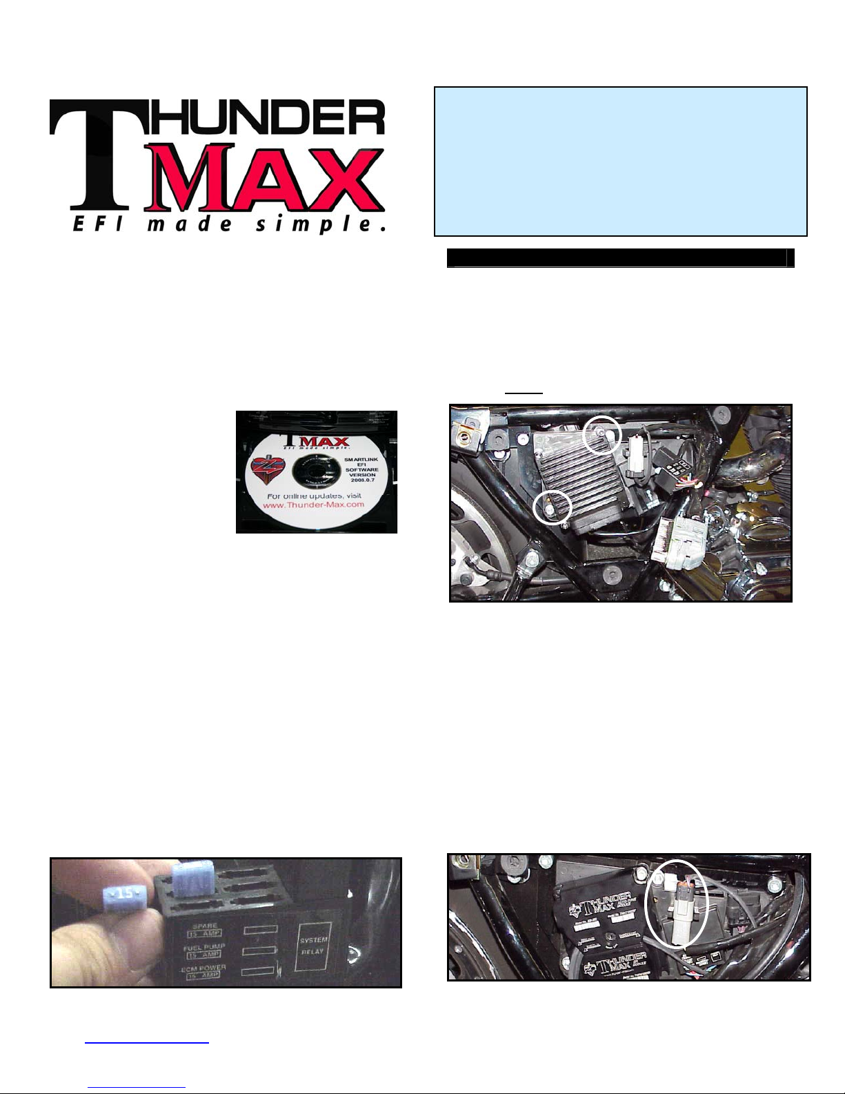
Step 1 Inse the SmartLink
CD into your computer.
SmartLink will automatically
open the InstallShield
Wizard when the computer
finds the CD-Rom. Follow
the instructions and install
the software on your
computer. If you do not have a serial port on your
computer for the communication cable, you will need to
use a USB to Serial converter (an inexpensive converter
is available from Zipper’s, #372-000). Install the included
driver disc at this time; follow the instructions given by
the manufacturer of the converter for installation.
Step 2
equipped) modules. Special Note: Module location on
some model motorcycles (notably all Dyna® and
Softail® Rocker® models) makes it difficult to insert the
communication cable once the module is installed. An
8” ‘pigtail’ harness is available (# 309-324) that can be
permanently connected to the bike’s ECM harness plug,
allowing a remote port for the communication cable if
desired. Compatible with ThunderMax ECM serial
number 114000 or higher (starting August 2008).
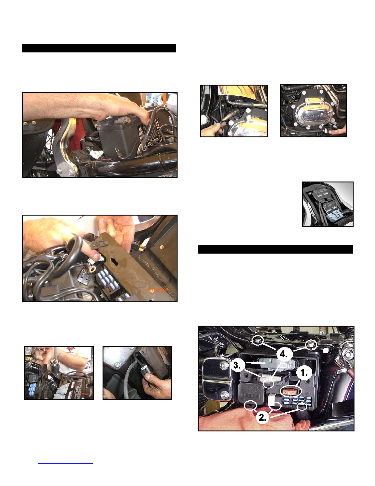
fuse, remove fuse labeled “ECM POWER”.
rt
Install the Th
- Locate the fuse box that contains the EAll Models
underMax and AutoTune (if
CM
Installation / Setup Guide
Please Note: This product is Legal in California
only for racing vehicles which may never be used
upon a highway.
product for his or her use. Installation and use on a pollution-
controlled vehicle constitutes tampering under the U.S. EPA
guidelines and can lead to substantial fines. Review your
application and check your local laws before installing.
The user shall determine suitability of the
Touring Models
FL-A. Unplug the ECM wiring harness from the factor
CM.
E
L-B: Remove the factory ECM from the motorcycle
F
e ECM is held to the electrical caddy by socket he
th
p screws. The screws have a locking agent on th
a em
c
nd can be difficult to remove. Work the screws back
a
and forth slowly
FL-C: Install the ECM wiring harness to the
ThunderMax ECM. Do not install the ECM onto the
motorcycle at this point. If the ECM is mounted onto the
electrical caddy at this step, it is difficult to get the fuse
box in place.
FL-D: Route the AutoTune harnesses (if equipped)
through the frame opening before positioning the ECM
for installation. Re-install the ECM fuse and secure th
fuse box back into position on the electrical caddy.
FL-E: Mount the ThunderMax ECM onto the electrical
caddy using the two factory socket head cap screws.
Plug the Auto
port (shown).
to break them loose.
e
Tune harness into the 4-pin gray data
y
,
ad
www.Thunder-Max.com 309-360 Installation / Setup Guide V2009.04.23 ProductSupport@ZippersPerformance.com
1
Page 2
Softail® Models
ST-A: Remove the seat, locate and remove the ECM
fuse. Remove the stock ECM from the motorcycle and
the wiring harness plug from the ECM. Lift the battery
up from the oil tank and remove the battery cables
(negative first). Remove the battery.
ST-B: Remove the bolts holding the fuse block bracket
to the frame and lift the bracket away from the frame to
allow access to the gap between the frame and oil tank
on the right side of the motorcycle.
ST-C: Connect the ThunderMax ECM to the harness
and position it loosely in the ECM tray. Feed both
oxygen sensor harnesses (front cylinder first) through
the gap between the frame and oil tank on the right side
of the motorcycle.
and tightened into the exhaust pipe, so the harness can
turn freely). Ensure that the rear O
harness plug is
2
positioned closer to the swingarm pivot bolt so it will not
be crushed between the upper swingarm and the oil tank
at full stroke (suspension bottomed).
ST-E: Position the harness plug for the front pipe under
the transmission, along the frame rail. Install the oxygen
sensors into the exhaust pipes, connect the harness
plugs to the oxygen sensors and secure the harnesses
west point) to the frame (above the lo
with wire ties.
ST-F: Re-install the fuse block
bracket bolts and attach the
ThunderMax ECM to the ECM tray.
Re-install the battery (positive cable
first) and install the ECM fuse.
Plug the AutoTune module into
e 4-pin gray data port plug on th
the motorcycle.
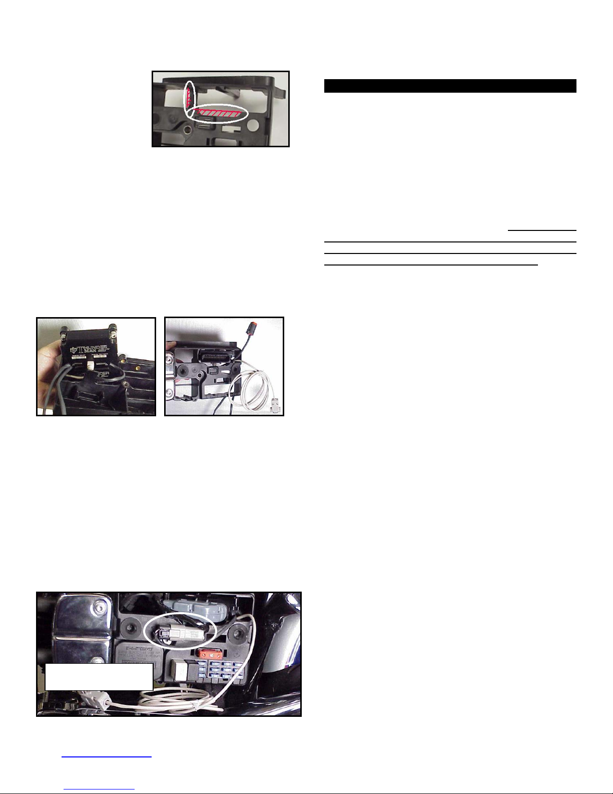
FXD (Dyna®) Models
FXD-A: Remove the left side cover to reveal the
electrical caddy. Remove the main fuse (1). Use a
small screwdriver to release the catche
block, relay block and TSSM module to the electrica
caddy (2). Unplug the main harness fr
remove the data plug from its holder (3
hex head and 1 socket head mountin
caddy for removal (4). Unplug th
harness from the coil and remove the c
s holding the fuse
om the ECM and
). Remove the 2
g bolts to free the
e plug wires and
addy.
l
ST-D: At this time you may want to snake the rear
oxygen sensor towards the rear exhaust pipe by starting
it from the right side of the bike, under the oil tank, and
around the seat post to the rear exhaust position (do not
connect it to the harness until after it has been installed
www.Thunder-Max.com 309-360 Installation / Setup Guide V2009.04.23 ProductSupport@ZippersPerformance.com
2
Page 3
FXD-B: Remove the
stock ECM from the
electrical caddy. The
caddy must be slightly
modified for additional
main harness
connector clearance.
Use a Dremel or Roto-Zip tool to provide additional
clearance for the harness plug catch; also remove
approximately 3/8” from the partition support as shown.
FXD-C: Because of the impossibility of connecting the
communication cable without disassembly once
assembled on FXD models, the cable should be
permanently installed to the ThunderMax, or the optional
‘pigtail’ harness m
communication cable, and
feed it and the AutoTune
ECM plug port of the cadd
caddy as shown. The ox
exit towards the opposite side of the cad
entioned in step 2 used. If using the
if equipped with AutoTune,
power harness through the
y and mount the ECM to the
ygen sensor harnesses should
dy.
FXD-D: If equipped with AutoTune, before reinstalling
the caddy, feed the front cylinder oxygen sensor harness
through to the right side of the bike, over the top and to
the rear of the starter motor. Reinstall the caddy with
fuse and relay blocks in place. Reconnect the TSSM,
coil and ECM harnesses and main fuse. If equipped
ith AutoTune, plug the closed loop module into the
w
4-pin gray data link on the bike. It is through the data
port that data from the AutoTune module is transferred
to the ThunderMax. A ‘Y’ harness is available (# 309-
343) to keep an open data port if desired. After
programming and setup, the communication cable can
be coiled up and kept under the caddy cover if not using
the ‘pigtail’ harness.
Dyna®: ECM installed with
communication cable attached.
Oxygen Sensor Installation (AutoTune)
If equipped with AutoTune, install supplied wide band
oxygen sensors in the front and rear exhaust pipes.
FXD and all 2007-up models are equipped with
2006
narrow band sensors, which must be removed and
replaced with the supplie d units. The wide
band sensors are long factory sensors.
Installation of the wide ors into factory
headpipes presents no lems, however,
d wide ban
er than the
band sens
clearance prob
some aftermarket pipes may require exhaust pipe
mo bung relocation for interference-
dification or sensor
free sors must mount freely without
installation. The sen
contacting surrounding components. If this is not
possible, do not attempt to bend or modify the
sensor in any way as it is a sensitive electronic
component and will be damaged if you do. Modify
the pipe if required for clearance. Weld-in bungs are
available for exhausts systems not equipped with bungs
or if current bungs present clearance issues. Bungs
should be located no more than 3-4” from the head/pipe
connection (for ideal location, refer to the factory location
on 2007-up models). Weld-in bungs are available from
Zipper’s (#272-200, straight; #272-202, angled). After
installation, route the sensor harness away from the
engine and along the frame when possible, above the
lowest frame point to avoid the possibility of dragging
ground during operation. Avoid routing harnesses where
engine movement or moving parts can contact and
damage the harnesses or connector plugs.
Connect the sensors to the closed loop module. The
AutoTune harness for the rear cylinder sensor is shorter
and can be easily identified by black tracers on all of its
wires; both plugs are clearly marked for front and rear
use. It is very important to install these correctly or the
engine will perform poorly! Tie the harnesses to the
frame or existing component harnesses, taking care to
avoid contact with any vibrating component that may
chaff the sheathing or wires. Some disassembly of bike
components may be required for best harness routing.
FXD Tips: The rear harness mounts easily, just coil
the excess wires and locate them above the
transmission. The front harness should travel from the
AutoTune module, over and to the rear of the starter
motor, behind the exhaust support bracket and between
the crossover pipe and the transmission.
Remove the footpeg/brake pedal bracket mounting bolts
and move the assembly towards the exhaust pipe.
Route the front exhaust sensor harness under the cam
cover exhaust support bracket and behind the brake
pedal; connect it to AutoTune harness.
The sensor plug and harness will drop down to the frame
rail with a little brake pedal wiggling where it can be ziptied to the frame rail, out of sight and out of harm’s way.
www.Thunder-Max.com 309-360 Installation / Setup Guide V2009.04.23 ProductSupport@ZippersPerformance.com
3
Page 4

Step 3 Load a Base Map to your SmartLink software.
Selecting a base map for your ThunderMax is easy
thanks to the filtering system in the SmartLink software.
Open SmartLink; from the toolbar choose [EFI Maps]
[EFI Map Listings / Definitions]. You should first
update the Map Definitions file to ensure you have the
latest available maps. Close the [Base Map
Definitions] window, then click the [Check Internet For
Updates] button (requires internet connection; follow
prompts). After updating, select [Select BaseMap].].
Second, place your curser over the ‘Throttle’ column
and right click your match.
Third, right-click the ‘Exhaust’ type that closest matches
your application.
Available base maps will be shown (if the [Clear Filters]
button at the
it to clear filtered maps so all maps will be shown).
lower left of the screen is highlighted, click
Fourth, right click the ‘Muffler’ column if further definition
of the exhaust system is required (depends on exhaust
application). Keep right-clicking the application columns
until you have located the best map match (in the case
of identical maps, choose the latest date). Highlight the
map you’ve chosen (left-click; blue bar indicates
selected map) and click [Close] button. This brings you
to the ‘Base Map Name Encoding’ page, from which you
can review the map parameters. Click the [Load
BaseMap] button to load the map into the software.
Filter the maps to locate a base map that best matches
your application by placing your curser first over any
‘Engine Type’ that matches your engine and right-click it.
All maps that do not match your selection will be filtered
from the screen.
www.Thunder-Max.com 309-360 Installation / Setup Guide V2009.04.23 ProductSupport@ZippersPerformance.com
From this page you can load the base map into the
tware by clicking the [Load Base Map] button.
sof
[Close] this page to view the open map page. From the
‘Tuning Maps’ Tree, click the + sign next to [Module
4
Page 5

Configuration], then double-click ‘Basic Settings’.
The basic pa settings ge opens. Check to see if the
[Speedo Cal] calibra tches ear and
model; if not, click th c alue as
shown, then click [Close].
tion setting ma
e button, enter the
your y
orrect v
Speedometer Calibration Settings
Dyna®
2004-2005 FXD 40960
2006-2007 FXD 45900
2007-up CVO 42450
Softail
2008-up FXD 42450
2001-2003 4352
©
2004-2006 40960
2007-up 42450
2002 4352
Touring
2003 20480
2004-2006 40960
2007-up (16”)
2007-up (17”)
42450
42000
Step 4
closed loop operation (closed loop operation requires the
AutoTune module and wide band se aps
will initially open as ‘Closed Loop Configured’ by defau
To change or edit these settings, select [Configure]
[Closed Loop MODULE Settings] from the toolbar to
open the dialog page. This page is divided into two
while the s. The
ap’ side is used to store the settings you desire the
‘M
ase map to dictate to the module. The ‘Module’ side,
b
ditable only when linked to the module, can be used
e
ter to override the map settings if desired.
la
Next is to configure the module for open or
nsors). Most m
lt.
e left side controhalves, th
lling the ‘Module’ settings
right side controls the ‘Map’ setting
F
or closed loop (AutoTune) operation, click the ‘Closed
L
oop Processing’ box. For open loop operation, this box
s
hould not be not be checked (click checkmark to un-
c
heck). Close the window. Once linked, the system
d
etects if an AutoTune module exists on the bike and will
in
form you via screen message if there is a mismatch.
tep 5 Now you are ready to ‘Link’
S
a
nd ‘Write’ the map to the ECM.
A
ttach the communication cable
from your computer to the
ThunderMax module, making
certain that the cable is routed away
from any part of the motorcycle that
generates heat.
Special Note for International Model Bikes with
Active Exhaust Enabled: If your bike is equipped with
a working Active Exhaust Valve, you must unplug the
active exhaust harness before linking to the module, as
the AEV circuitry conflicts with the communication
stream. You can re-connect the harness after unlinking.
If the stock exhaust has been changed, disregard this
tep. ThunderMax does not support active es
xhaust
Step 6 To link to the module, turn the key switch to the
“Ignition” position, making OFF”
rocker switch (Kill Switch) s is in
the “RUN” position. Select
S a
martLink software. The button turns green to indicate
successful link. Answer [No] to the “Do you wish to
READ the module map now” question at this time.
From the toolbar, click [File] [Write M
Settings], answer OK to the message
that you are about to overwrite the curr
module; the transfer bar appears during t
Step 7 Verify Module Settings. Bef
step, clear any a ctive Diagnostic Code readings. While
linked, from the Tuning Tree select [Module
Configuration] [Diagnostic Codes].
certain the “RUN /
on the handlebar control
the “Link” Button in the
odule Maps and
that informs you
ent map in the
he map load.
ore performing this
www.Thunder-Max.com 309-360 Installation / Setup Guide V2009.04.23 ProductSupport@ZippersPerformance.com
5
Page 6

When the Diagnostic Codes window appears, select
[Clear Diagnostic Codes]. After completing this step,
select Basic Settings from the Module Configuration
menu and verify that the speedometer calibration is
correct and if the bike is a 2007 or later model the 6
th
gear indicator settings are correctly set (Final drive ratio
[87] for Touring & Softail®, [84] for Dyna® models) Gear
6 Min TPS [40]). After verifying these settings, click
[Write Basic Settings]. If the installation is to be
operated in closed loop mode (with AutoTune module),
select [Configuration] from the toolbar menu and
ed Loop Configuration]. Verify that the [Closed
[Clos
click
Loop Processing] and [AutoTune] boxes are checked
√ on the left (module) side of the window.
gauges that you deem important; if too many are chosen
your screen may appear cluttered.
Step 9 Select the “Monitor” button to active the gauges.
It is located beside the “Link” button and will turn green
when the monitor gauge functions are live. The gauges
will be displayed if they were not already on the screen.
Step 10 Now select the IAC Stops vs. Engine
Temperature ” menu within the
tree. Strik
tuning e the
page from “IAC Curves
IMPORTANT STEP BEFORE STARTING
Next, ‘Initialize’ the ThunderMax ECM. Initializing
synchronizes ‘home’ positions for the TPS and IAC, and
is a required step any time battery power has been
interrupted or established to the ThunderMax ECM.
With the handlebar switch in the ‘ON’ position, cycle
the key switch on and off 3 times, leaving the
ignition on for 30 seconds, then off for 30 seconds,
each cycle. DO NOT start the engine or move the
throttle during this process. After 3 on/off cycles, make
certain that the motorcycle is in neutral and start the bike
2 times, letting it settle at idle for 10 seconds; the idle
should be smooth and steady. Some engines may
require several on/off engine starts to initialize properly.
This initialization process must be performed any
time battery power is interrupted to the module (after
battery servicing/winterization, etc). After initialization,
shut off the engine, but stay linked for step 8.
Step 8 Before re olbar click
nitoring] [Show Gauges]. The “Engine Spe
[Mo ed”,
e , AFR
“Engin Head Temp”, “IAC Position”, “AFR Front”
starting the engine, from to
Rear” and “AFR Target” gauges are automatically
formatted and are shown on the screen. Additional
gauges can be created if desired (see SmartLink Tuning
Manual under Help menu), but the above gauges are
most helpful during initial set up. You may select any
spacebar to show the actual values of the tuning block
(use left/right arrow keys to move the block marker).
Make certain that the motorcycle is in neutral and the
engine is cold, and then start the engine. Once the
engine idle is stable after 15- 20 seconds, select the
“IAC-Auto” button (Idle Air Control Auto Adjustment).
Allow the “IAC-Auto” function to run at idle until the
engine head temperature reaches 275 degrees. After
reaching temperature of 275 degrees, the “IAC-Auto”
function automatically shuts off. You can terminate this
function at any time, and re-run it at a later time if you
wish.
Step 11 Unlink the SmartLink software from the ECM,
turn off the ignition switch and remove the
communication cable from the Thunde
the ‘Save As’ command to create a folder and save the
map to your hard drive. The motorcycle is now ready to
be ridden. Several riding sessions that allow the engine
to reach normal operating temperature should be
completed. During this process, the IAC virtual stops will
automatically be adju t
sted to the IAC target values se
within the map’s basic settings. This feature
automatically adjusts how the engine comes back to the
specified idle speed. If t s are set too low, the
he IAC stop
engine will dip below the specified idle speed during
n transient conditions. If the IAC stop
certai s are above
the IAC position, the engine will idle ab
ified in the idle speed vs. engine te
spec mperature page.
If it determined that these automatic adjustments ha
not resulted in satisfactory operation of the engine,
consult the SmartLink Manual (available under the Help
section of the toolbar), Section 3 (Tuning the
ThunderMax ECM) for further adjustment procedures.
rMax ECM. Use
ove the idle rpm
ve
www.Thunder-Max.com 309-360 Installation / Setup Guide V2009.04.23 ProductSupport@ZippersPerformance.com
6
Page 7

CLOSED LOOP PROCESSING
When equipped with AutoTune, your SmartLink software
will allow you to set Air/Fuel tuning parameters for your
ThunderMax and its installed base map. To set the
AutoTune Limits, go to the toolbar and click [Configure]
[Close Loop
The Closed Loop Configuration dialog page opens; the
right side shows the default MAP settings stored in the
MAP file (settings are applied to the installed base map
during the ‘Closed Loop Format’ conversion performed
by SmartLink), while the left side shows what the module
is currently set to (unadjusted, these settings will mirror
P’s settings). MA
T e un-highlighted left ‘MODULE’ side of the pag
h e
ows editing of those settings within the MODULE fo
all r
tuning purposes, while unaffecting the MAP settings. To
edit module settings, click the [Link/Read (Module)]
button (left side highlights/active). You can now edit
these settings within the live module
change any of the settings from the MAP
settings.
Closed Loop Processing (Module) – Check [ON] to
nable closed loop AutoTune processing. During closed
e
op processing, the ThunderMax module processes
lo
edback from the oxygen sensors to adjust the fuel
fe
olume at all points by creating learned “offset” points
v
om the installed ‘base map’ fuel points. The ‘static’
fr
ase map is dynamically used by the ThunderMax
b
odule and the AutoTune’s active (closed loop)
m
edback system. This system optimizes the fuel points
fe
fit the target air/fuel ratio through ‘learned offset
to
oints’. These ‘learned offset points’ are stored within
p
e ThunderMax and are used in conjunction with the
th
ase map. The ‘base map’ fuel points are not being
b
adjusted by either the AutoTune or ThunderMax
modules.
MODULE Settings].
should you want to
default
If AutoTune Closed Loop Processing is un-checked, fuel
points will be adjusted to the last learned offset points, or
if no learning ha
s occurred, to the original base map
points. Stored offset points remain within the module; in
the event that power is interrupted for any reason, the
learned offset points remain until re-learned or cleared
under the [Map Editing] toolbar menu.
Air Fuel Ratio Override (Module) – A single Target
AFR setting can be applied using this command.
Clicking this box and changing this number overrides
ALL ‘Air/Fuel Ratio vs. TPS’ pages at all
RPM’s. To
target specific Air/Fuel Ratio RPM ranges and throttle
positions, leave this box unchecked and edit the
individual ‘Air/Fuel-TPS @ RPM’ map pages located
under the [Tuning Maps] tree. Individual Air/Fuel
targets are pre-set within the base map to provide a
good balance between power and economy. Individual
cell throttle position/rpm AFR targets can be viewed and
adjusted on these pages. Use the left/right arrow keys
to navigate the individual blocks (strike the spacebar to
view the values); use the up/down arrow keys to adjust
the values. Click the [Monitor] button when linked live
and a vertical bar will show the actual throttle position.
See the SmartLink manual for further tuning instructions.
ldle Air Control Override (Module) - Check [OFF].
This setting should not be checked on except for
iagnosing a particular type of supported problem or
d
uring tuning on a load cell dyno. Changing this setting
d
will lead to starting and idling problems.
Maximum CLP Offset (Module) – [Session (Module)]
button sets the AFR maximum learning correction from
the base map’s fuel setting per session by percentage
(range is 0-10%). A ‘session’ is defined as the period of
time from engine on to engine off (per cycle).
[Maximum (Module)] button sets the total AFR
maximum learning correction from the base map’s fuel
setting by percentage (regardless of number of sessions;
range is 10-25%). Unless your application is a
considerable mismatch to the installed base map, the
default settings of 5 and 20 percent are sufficient for
most AFR corrections.
You should always pick the best possible map match
during the selection of your base map. The theory
behind this is to reduce the range and time the closed
loop system needs to learn offsets (corrections) for the
target AFR. If your map selection is a poor match to the
application, the amount of learning needed will be
significant. Review the parameters of your base map vs.
available base maps under ‘Base Maps Listing’ to
ensure you have the best map match and the latest
version of the map.
www.Thunder-Max.com 309-360 Installation / Setup Guide V2009.04.23 ProductSupport@ZippersPerformance.com
7
Page 8

TIPS AND GENER• INFORMATION
Several support features are located under the
[Help] menu; some require an internet
connection.
• A comprehensive Tuning Manual in PDF
format is included on the CD for viewing and
printing from your desktop.
• When the SmartLink program is opened, it
will automatically retrieve and open the last map
that was open.
• Any time you link to your motorcycle: Read
the map that is installed in the ThunderMax
ECM by selecting [File] then [Read Module
the SmartLink toolbar. Maps and Settings] on
This will synchronize the map file loaded into the
ThunderMax ECM with the SmartLink software.
• 2003 FLT/FL H-D® used 2 different
HT models:
speedometer calibrations during the extended
2003 model production. Which calibration you
may need is easily identified by checking the
part number on the back o
f your factory ECM.
Calibration 20480 is used if the part number
ends in -03, while 4352 is used if the ECM p/n
ends in -02. If your turn signals don’t cancel on
a 2003 model, try the alternate setting.
• 2007-up Big Twin models: There are two
settings in the [Module Configuration] [Basic
Settings] page that should to be set to the
following to enable the 6
th
gear indicator light to
function:
Final drive ratio [87; 84 for 06-07 Dyna®]
Gear 6 Min TPS [40].
• Sportster® models: The [Main Relay Loc]
must be set to “1” under the [Basic Settings]
[Module Configuration] page, or the engine will
not start.
• Accel Fuel is be used to tune throttle response
(go to [Module Configuration] [Basic Settings]).
• AFR Correction vs. Engine Temperature page
is used to adjust cold start AFR’s. It is active yet
should be used with extreme caution. Any
changes made to this page affects all maps, at
every throttle position, every 256 RPM’s! See
SmartLink Tuning Manual for procedures.
AFR vs. Engine Temperature is active yet at
•
this time you should be discouraged from
making any changes to this page.
AL
• Air/Fuel-TPS @ RPM
These pages reflect
desired targets of AFR to throttle position at
every 256 RPM. Example: if you desire a leaner
mixture for added fuel economy then you can
easily make multi-tiered AFR targets at specific
throttle positions and RPM’s that will be learned
during closed loop processing.
• During warm-up, the AFR on both cylinders will
be richer than the target AFR at normal
operating temperatures; this is a normal part of
the warm-up map. AutoTune and its targets are
inactive below 200 degrees.
ratios• Target air/fuel can be viewed on the
Air/Fuel-TPS @
RPM pages. When these
pages are open, you can view the target AFR by
clicking on a dot and ta
view the ta
that RPM. Use arrow keys to raise/lower targets.
• to the module
Writing new or modified maps
rget at a specific throttle position for
pping the space bar to
requires the system to be re-initialized (Step 7),
and any existing learned fuel and IAC
adjustments to be cleared (Map Editing, clear).
Linking and editing an existing map within the
module does not
require above steps.
• System Updates are available through
SmartLink with an internet connection.
Software, Firmware and Map updates can be
downloaded; check frequently for u
In-Tank Fuel Filters
• should be inspected as a
pdates.
part of routine maintenance. The filter is small
and one bad load of fuel can clog it. The factory
recommended service interval is 25K miles.
• Save your edited maps to your hard drive
using the [Save As] command. Document the
changes in [Map Notes] located under [EFI
Maps on the toolbar. These notes are stored
with the saved map; remember to edit them
when making changes for future reference.
• Oxygen Sensor Care: Items that can damage
or shorten the life of your sensors:
Leaded fuel – Race fuel
Oil deposits from oil consumption problems
Excessive moisture exposure
Excessive (extreme) heat
There is no warranty on sensors. Replacement
P/N is 309-355.
www.Thunder-Max.com Installation / Setup Guide V2009.04.23 ProductSupport@ZippersPerformance.com
8
 Loading...