

Page 1
THUNDER LASER
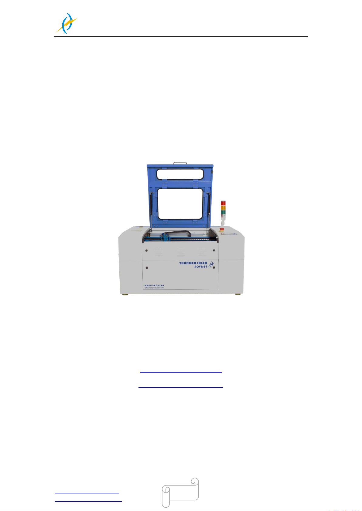
NOVA-24
www.thunderlaser.com DONGGUAN THUNDER LASER EQUIPMENT CO.,LTD
[email protected] Shatian Town, Shatian Dadao, Mintian
Dongguan City, Guangdong Province, China
1
THUNDER LASER
SYSTEMS
User’s manual for NOVA-24
www.thunderlaser.com
December, 2019
Original Instruction
Tel :(86)769 826653
Page 2

THUNDER LASER
NOVA-24
www.thunderlaser.com DONGGUAN THUNDER LASER EQUIPMENT CO.,LTD
[email protected] Shatian Town, Shatian Dadao, Mintian
Dongguan City, Guangdong Province, China
2
Introduction
(At the same time,
you can also refer to the machine installation video that we posted on youtube.
The specific URL is
This manual has been designated as the thunder laser systems, laser cutting
machine installation and user guide;The manual is divided into five chapters,
Including general information instructions, safety instructions, the key
components of every laser cutting systems and the
instructions and maintenance instructions from THUNDERLASER Company.
Frist, it should be emphasized that the installation of each system must meet
the requirements, and make it consistent with the installation requirements of
THUNDERLASER. If not, the machine will not working properly,poor performance,
life shortened,maintenance costs increased and even machine damage .
The note is for getting a specific requirement of system installation,and we
hope every customer try to understand these notes before installation and usage,
thus you can correctly install and use. If you meet any installation problems,
you can contact our technical staff and customer service staff.
http://www.thunderlaser.com/how-to-use-your-laser-machine/how-to-setup-your-nova-las
er-cutter.html Or
https://www.youtube.com/watch?v=NpLo1L0NQx8&list=PLjSZrgjcrhs7QucNN-3jx7rZapDGfj
G-5 .)
installation steps, operation
Tel :(86)769 826653
Page 3

THUNDER LASER
NOVA-24
www.thunderlaser.com DONGGUAN THUNDER LASER EQUIPMENT CO.,LTD
[email protected] Shatian Town, Shatian Dadao, Mintian
Dongguan City, Guangdong Province, China
3
Contents
Chapter1 General ................................................................................................................................ 5
1.1 General Informa tion .........................................................................................................................5
1.2 Designated ........................................................................................................................................6
1.3 Dis posal r em arks ..............................................................................................................................6
1.4 Technical Data / Device Specification ............................................................................................7
1.5 Manufacturer's Label........................................................................................................................9
Chapter2 Safety ................................................................................................................................ 10
2.1 General Safety Information ...........................................................................................................10
2.2 Laser Safety Information ............................................................................................................... 11
2.3 Safety Precautions w he n Operatin g the De vice ...........................................................................12
2.4 Warni n g a nd I nf o rm atio n L abels ...................................................................................................13
Chapter3 Process of Installing ......................................................................................................... 16
3.1 Unpacking .......................................................................................................................................16
3.2 Location ..........................................................................................................................................17
3.3 Before Installation ..........................................................................................................................18
3.4 Exhaust System – Requirements ...................................................................................................20
3.5 Air System – Requirements ...........................................................................................................20
3.6 Wate r Coolin g Sys te m – Requirements ........................................................................................21
3.7 Computer – Requirements .............................................................................................................22
3.8 Connections ....................................................................................................................................23
3.8.1 Connecting the Mains .......................................................................................... 23
3.8.2 Connecting the Computer.................................................................................... 24
3.8.3 Connecting the Exhaust System ......................................................................... 25
3.8.4 Connecting the Air System.................................................................................. 27
3.8.5 Connecting the Cooling System ......................................................................... 29
Chapter4 Operation .......................................................................................................................... 30
4.1 Machine View .................................................................................................................................30
4.2 ON/OFF Switch ..............................................................................................................................35
4.3 How to setup the software .............................................................................................................36
4.3.1 Software ins tallation ............................................................................................ 36
4.3.2 Make connectio n betwee n PC a nd ma c hine....................................................... 38
4.4 How to use the display ...................................................................................................................42
4.4.1 Funct i o n of the Buttons ....................................................................................... 42
4.4.2 The main interface ............................................................................................... 44
4.4.3 Speed button ......................................................................................................... 45
4.4.4 Max Power buttons .............................................................................................. 45
4.4.5 Set the Layer Parameters ..................................................................................... 45
4.4.6 Z/U button ............................................................................................................ 46
4.4.7 File button ............................................................................................................ 47
4.5 How to use the different nozz l es laser he ad co ne ........................................................................50
4.6 How to re place t he 4 i n ch an d H R laser he ad ...............................................................................51
4.7 How to adjust focus distance by manual or auto ..........................................................................53
4.8 How to use the TL-Timer...............................................................................................................56
4.9 How to use air-assist control..........................................................................................................58
Tel :(86)769 826653
Page 4

THUNDER LASER
NOVA-24
www.thunderlaser.com DONGGUAN THUNDER LASER EQUIPMENT CO.,LTD
[email protected] Shatian Town, Shatian Dadao, Mintian
Dongguan City, Guangdong Province, China
4
4.10 How the he at al ar m syste m wo r ks ............................................................................................60
4.11 The First Time Run ning the L aser ............................................................................................61
4.12 W orkstation Area Indication ......................................................................................................64
4.13 How to use the Rotary axis Attachment....................................................................................65
4.14 For Laser Engraving...................................................................................................................67
Chapter5 Maintenance ..................................................................................................................... 68
5.1 Cleaning the Laser Machine ..........................................................................................................68
5.2 Cleaning the Optical Parts .............................................................................................................69
5.2.1 Cleanin g the Focus Lens ..................................................................................... 69
5.2.2 Cleaning the Mirrors............................................................................................ 71
5.2.3 Cleaning Laser Combiner.................................................................................... 73
5.3 Maintain the X/Y/Z Rails ..............................................................................................................74
5.4 Check the Beam Path .....................................................................................................................75
5.5 Change Cooling Water for The Water Chiller ..............................................................................76
5.6 Maintenance Plan ...........................................................................................................................77
Tel :(86)769 826653
Page 5
THUNDER LASER
NOVA-24
www.thunderlaser.com DONGGUAN THUNDER LASER EQUIPMENT CO.,LTD
[email protected] Shatian Town, Shatian Dadao, Mintian
Dongguan City, Guangdong Province, China
5
Chapter1 General
1.1 General Information
Please read and follow this Operation Manual carefully, before installation and operation.
Damage to persons and/or material can result from not following individual points of the
Operation Manual!
Operation of the system is only permitted with equipment and spare parts supplied or
listed in the spare parts and consumables lists.
Auxiliary equipment must be adjusted to the base machine (any queries to dealer or
manufacturer).
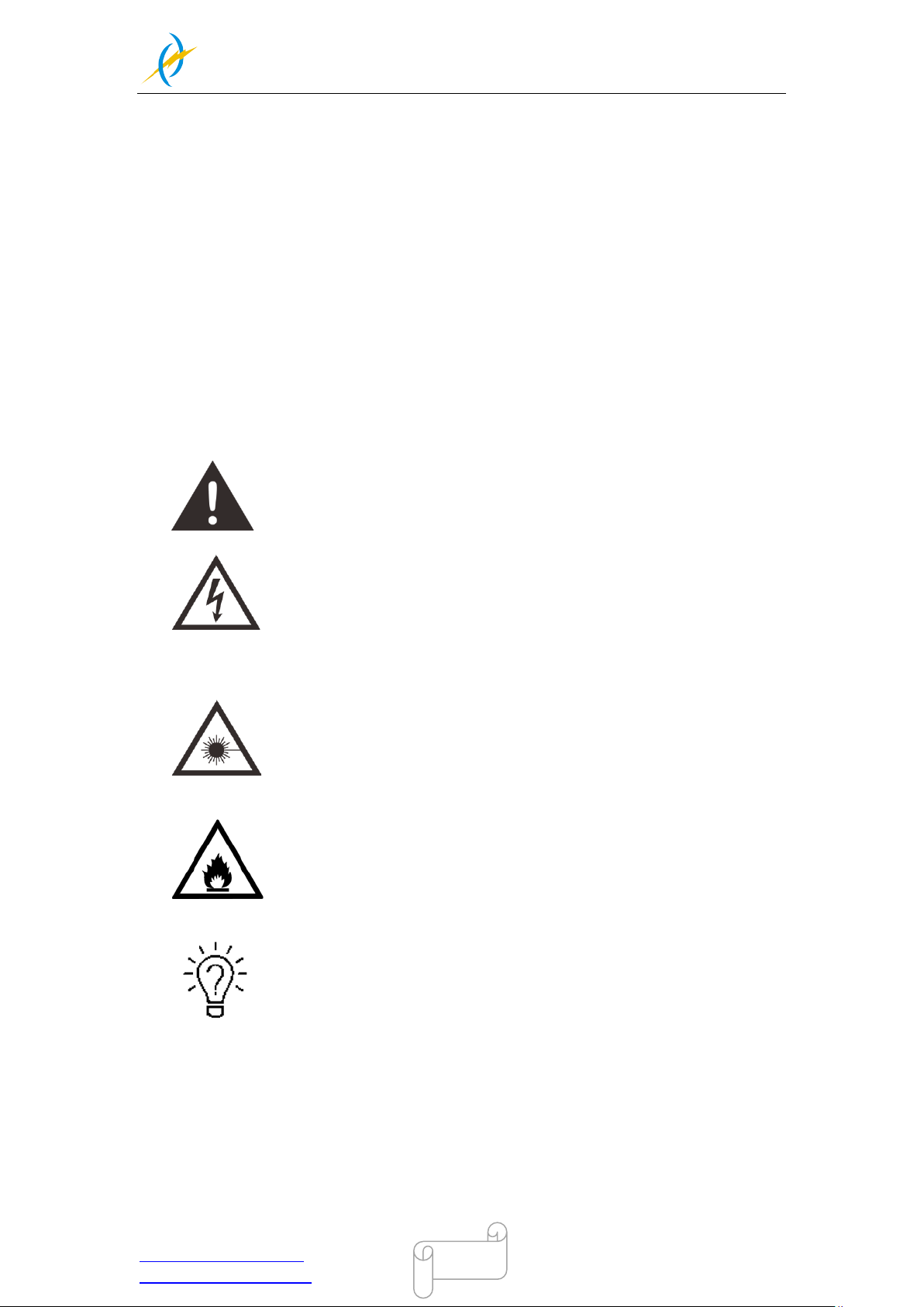
The following symbols are used for easier understanding of the Operation Manual:
Caution: Warning and caution to keep in mind when operate the laser.
Caution: This component is under voltage. In these areas strictly observe
the safety instructions regarding electricity. Care is to be taken in
particular during maintenance and repair work.
Caution: In this area pay attention to the possible dangers of the laser
beam.
Caution: Indicates the potential for fire danger when operation the laser.
Do not run the laser machine when unattended
Tips: Helpful note or information on individual components of the device
that simplify the use or make it more understandable.
Tel :(86)769 826653
Page 6
THUNDER LASER
NOVA-24
www.thunderlaser.com DONGGUAN THUNDER LASER EQUIPMENT CO.,LTD
[email protected] Shatian Town, Shatian Dadao, Mintian
Dongguan City, Guangdong Province, China
6
1.2 Designated
The THUNDER LASER NOVA-24 is used for engraving and cutting of signs, stamps
and suchlike.
A wide variety of materials such as rubber, acrylic, coated metal, tin, special steel,
anodized aluminum, cork, cardboard, glass, leather, marble, several plastics and wood
can be processed on the laser.
1. The engraving process must only be performed with a perfectly
adjusted machine.
2. For cutting applications with 40 W the use of the cutting table is
absolutely necessary.
3. Use of the system in other areas is against the designated use. The
manufacturer does not admit liability for damage to personal and/or
equipment resulting from such use.
4, The system must only be operated, maintained and repaired, by
personnel that are familiar with the designated field of use and the
dangers of the machine!
5. Non-observance of the instructions for operation, maintenance and
repair described in this Operation Manual excludes any liability of the
manufacturer if a defect occurs.
6. Caution when processing conductive materials (carbon fibers),
Conductive dust or particles in the ambient air might damage electrical
components and lead to short circuits. Bear in mind that those defects
are not warranted.
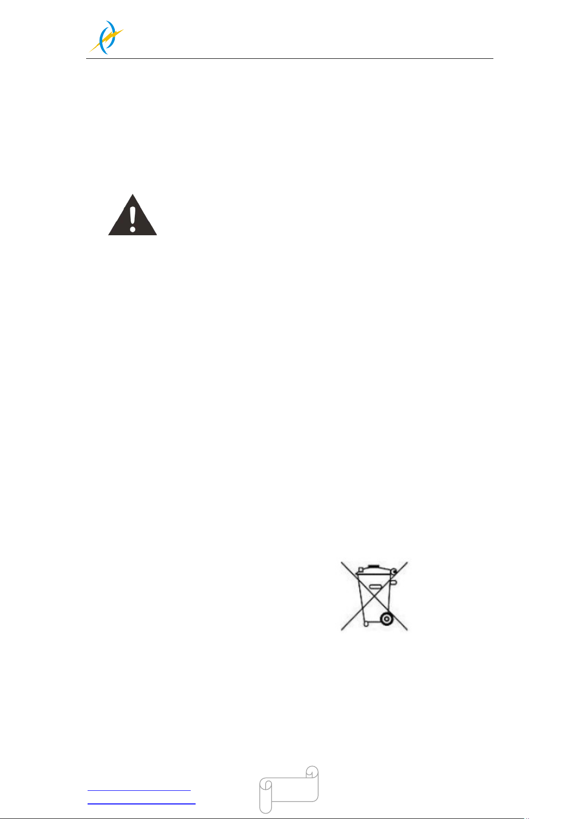
1.3 Disposal remarks
Do not dispose the machine with domestic waste!
Electronic devices have to be disposed according to the regional directives on el ect roni c
and electric waste disposal. In case of further questions, please ask your supplier. He
might take care of proper di spos al .
Tel :(86)769 826653
Page 7

THUNDER LASER
NOVA-24
www.thunderlaser.com DONGGUAN THUNDER LASER EQUIPMENT CO.,LTD
[email protected] Shatian Town, Shatian Dadao, Mintian
Dongguan City, Guangdong Province, China
7
1.4 Technical Data / Device Specification
Mechanics
Working area 23.6“x 15.7“/ 600 x 400 mm
Table Size 27.6“x 20.9“/ 700 x 530 mm
Z Axis Height 6.1 inch /155 mm
Max. Height of work piece (Motorized Table, Standard laser head) 6.1 inch / 155 mm
Max. Height of work piece (No Motorize Table, Standard Laser head) 1-2.1 inch /27- 55mm
Max. Engraving speed 39 inch/sec. / 1000 mm/sec. Standard
Cutting speed depending on material, thickness, laser power
Motor Easy Servo Motor
Drive Hybrid Servo Drive
Work piece table Solid metal (Honey comb table)
Max. load of work piece table 20 kg
Net Weight 130kgs (287Ibs)
Lenses available (focal distance) 2, 0”
Focus lens diameter 20mm
Reflector diameter 25mm
Beam combiner diameter 20mm
Dimensions
W x D x H 42.1“x 31.1“x 21.3“/ 1070 x 790 mm x 540 mm
Max Part Size (W x L x H)
Front Door Closed 27.6“x 20.9“x 8.3“/ 700 x 530 mm x 155 mm
Pass-Through Door 27.6“ x∞“x 0.6“/ 700 x∞mm x 10 mm
Features
Standard:
Open cover protection, Red Dot Pointer, Auto Focus, heat alarm system ,Motorized Table,
Pass-Through Door, Air pump, Water chiller, Exhaust Fan, Honey Comb Table,
2,0”(50.8mm)Focus Lens, Easily Adjustable Home Position, LCD Display, 3D Engraving,
“No Water “protection, Emergency Stop, Maintenance mode, TL-Timer, The warning light,.
Optional:
Rotary Attachment, High Resolution head (up to 1000DPI, while standard laser head Max
is 500DPI), High air compressor set (Includes water filter).
Control System
Laser power Adjustable from 1 - 100% (ty pic ally5-100%)
Interface Hardware USB: connect to PC and U-disk
Ethernet: connect to PC
Interface Software RDWorksV8
Operating Modes Optimized raster, vector, and combined mode
Buffer Memory 128 MB Standards
Tel :(86)769 826653
Page 8

THUNDER LASER
NOVA-24
www.thunderlaser.com DONGGUAN THUNDER LASER EQUIPMENT CO.,LTD
[email protected] Shatian Town, Shatian Dadao, Mintian
Dongguan City, Guangdong Province, China
8
Laser Equipment
Laser Type Sealed CO2 Glass Laser Tube
Wavelength 10, 6µm
Red dot pointer Laser Power< 1mW
Wavelength 630nm – 680nm
Cooling System
Air Cooling System Air-Cooled
Water Cooling System Water Cooled
Electricity, Power, Breaker
Electricity Requirement 110 to 240 volts, 50 or 60 Hz, Single phase
Power consumption 1100W (Assembly 40 Watt Laser Tube)
Recommended break 10A, 230V (40W/6W Laser Tube)
Ambient Conditions
Ambient temperature +15°C to +35°C / 59°F to 95°F
Humidity 40% to max. 70%, not condensing
Laser Safety
Laser class CDRH Laser Safety
CE compliant FDA approved
Laser Power: 40W, 60W
1200W (Assembly 60Watt Laser Tube)
10A, 115V (40W/6W/ Laser Tube)
Laser Class 2(H)
Tel :(86)769 826653
Page 9
THUNDER LASER
NOVA-24
www.thunderlaser.com DONGGUAN THUNDER LASER EQUIPMENT CO.,LTD
[email protected] Shatian Town, Shatian Dadao, Mintian
Dongguan City, Guangdong Province, China
9
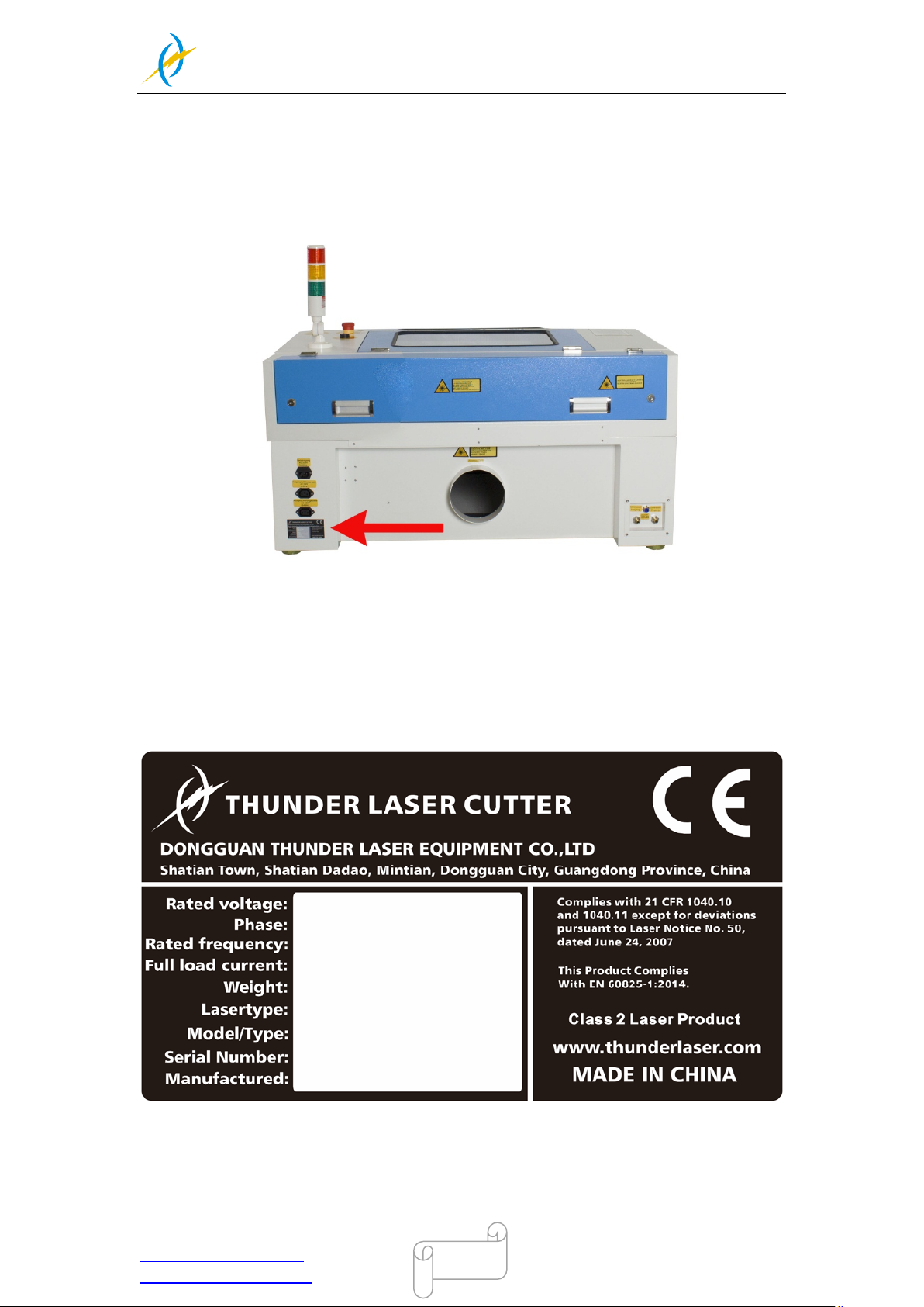
1.5 Manufacturer's Label
The manufacturer's label is located on the back of the device (see Figure below).
It is recommended to enter data such as serial number and year of manufacture into the
Manufacturer label below so that you always have this data handy if you have problems
with your device or require spare parts.
Tel :(86)769 826653
Page 10

THUNDER LASER
NOVA-24
www.thunderlaser.com DONGGUAN THUNDER LASER EQUIPMENT CO.,LTD
[email protected] Shatian Town, Shatian Dadao, Mintian
Dongguan City, Guangdong Province, China
10
Chapter2 Safety
2.1 General Safety Information
All personnel involved in installation, set-up, operation maintenance and repair of the
machine, must have read and understood the Operation Manual and in particular the
"Safety" section. The user is recommended to generate company-internal instructions
considering the professional qualifications of the personnel employed in each case, and
the receipt of the instruction/Operation Manual or the participation at introduction/training
should be acknowledged in writing in each case.
Safety-conscious of Working
The machine must only be operated by trained and authorized personnel.
The scopes of competence for the different activities in the scope of operating the
machine must be clearly defined and observed, so that under the aspect of safety no
unclear questions of competence occur. This applies in particular to activities on the
electric equipment, which must only be performed by special experts.
For all activities concerning installation, set-up, start-up, operation, modifications of
conditions and methods of operation, maintenance, inspection and repair, the switch-off
procedures that may be provided in the Operation Manual must be observed.
Safety Information for the User and /or O per atin g P ers onn el
1. No working methods are permitted that affect the safety of the
machine.
2. The operator must also ensure that no unauthorized persons work with
the machine (e.g. by activating equipment without authorization).
3. It is the duty of the operator, to check the machine before start of work
for externally visible damage and defects, and to immediately report
changes that appear (including behavior during operation) that affect
the safety.
4. The user must provide that the machine is only operated in perfect
condition.
5. The user must guarantee the cleanness and accessibility at and around
the machine by corresponding instructions and controls.
6. Principally, no safety components may be removed or disabled (already
here we emphasize the imminent dangers, for example severe burns,
loss of eye-sight). If the removal of safety components is required
during repair and service, the replacement of the safety components
must be performed immediately after completion of the service and
Tel :(86)769 826653
Page 11
THUNDER LASER
NOVA-24
www.thunderlaser.com DONGGUAN THUNDER LASER EQUIPMENT CO.,LTD
[email protected] Shatian Town, Shatian Dadao, Mintian
Dongguan City, Guangdong Province, China
11
repair activities.
7. Preparation, retooling, change of work piece, maintenance and repair
activities must only performed with equipment switched off, by trained
personnel.
8. It is forbidden to perform unauthorized modifications and changes to
the machine. It is emphasized, that any unauthorized modifications to
the machine are not permitted for safety reasons.
2.2 Laser Safety Information
1. To assess the potential dangers laser systems pose, they are
classified into 2 safety classes, thunder laser NOVA-24 is a device of
class 2. This is guaranteed by the protective housing and the safety
installations.
Please note that improper and warranty operation of the device can
override the status of Safety class 2 and can cause the emission of
harmful radiation.
2. This laser engraving system contains a carbon dioxide (CO2) laser of
class 2 that emits intensive and invisible laser radiation. Without safety
precautions the direct radiation or even diffuse reflected radiation is
dangerous!
3. Without safety precautions, the following risks exist with exposure to
laser radiation:
Eyes: Burns to the cornea
Skin: Burns
Clothing: Danger of fire
4. Never try to modify or disassemble the laser and do not try to start up
a system that had been modified or disassembled!
5. Dangerous radiation exposure can result from the use of operation or
adjustment equipment other than that described here, and if different
operational methods are performed.
Tel :(86)769 826653
Page 12
THUNDER LASER
NOVA-24
www.thunderlaser.com DONGGUAN THUNDER LASER EQUIPMENT CO.,LTD
[email protected] Shatian Town, Shatian Dadao, Mintian
Dongguan City, Guangdong Province, China
12
2.3 Safety Precautions when Operating the Device
In your thunder laser NOVA-24, a closed safety system is integrated which immediately
stop a job when the protection cover is opened. Consequently an incomplete engraving
can occur if the cover is opened during operation. Therefore, first press the "PAUSE"
button, if you want to interrupt an engraving process.
Please remember the following safety precautions when working with this device:
1. CO2 Fire extinguishers should be placed near laser. Always keep a
properly maintained and inspected fire extinguisher on hand.
2. Do not store any flammable materials in the inside of the device.
Particularly leftovers of produced materials have to be removed to
prevent fire hazard.
3. Please maintain Free air-flow surrounding this system. At all times, do
not cover during operation.
4. Stay with the laser. Do not leave the laser unattended when it is
working, small scraps can ignite and without supervision can destroy
the machine if not checked.
5. Use Air Assist. Always use the system’s Air Assist feature when vector
cutting.
1. These lasers emit invisible radiation; safety glasses should be worn
when maintenance these machines for your protection.
2. Adjustment of the beam path must be performed only by especially
trained personnel. An improper setting can lead to uncontrolled
emission of the laser radiation.
1. Do not disable limit switches or safety features as this can invalidate
warranties and cause damage to you and the machine.
2. Before processing materials the user must verify, whether harmful
materials can be generated and whether the filter equipment of the
exhaust system is suitable for the harmful materials. We emphasize that
it is the responsibility of the user, to consider the national and regional
threshold values for dust, fogs and gases when selecting the filters and
the exhaust system. (The values for the maximum workplace
Tel :(86)769 826653
Page 13
THUNDER LASER
NOVA-24
www.thunderlaser.com DONGGUAN THUNDER LASER EQUIPMENT CO.,LTD
[email protected] Shatian Town, Shatian Dadao, Mintian
Dongguan City, Guangdong Province, China
13
concentration must not be exceeded.)
3. PVC (polyvinyl chloride) must under no circumstances be processed
with the laser.
Should you have further ques tions before starting work, please feel free to write us
an email at: [email protected]
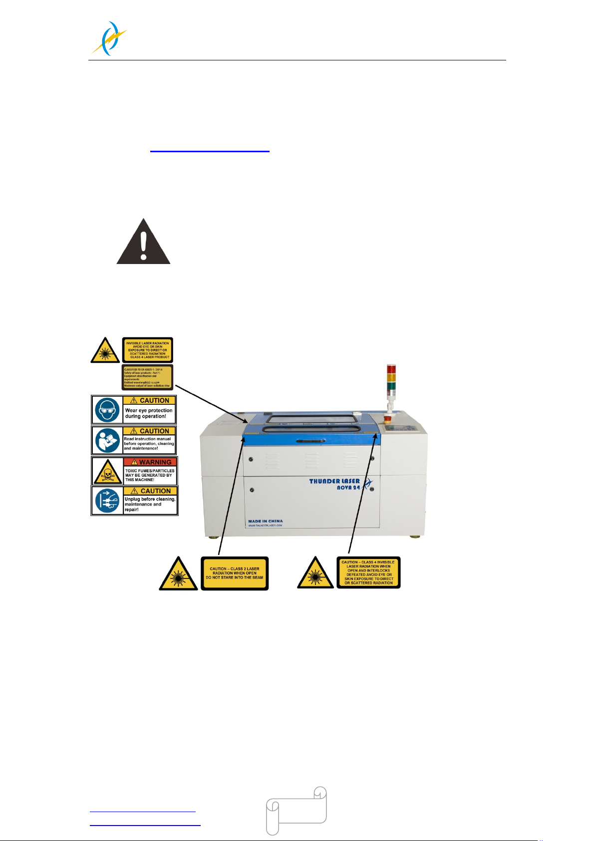
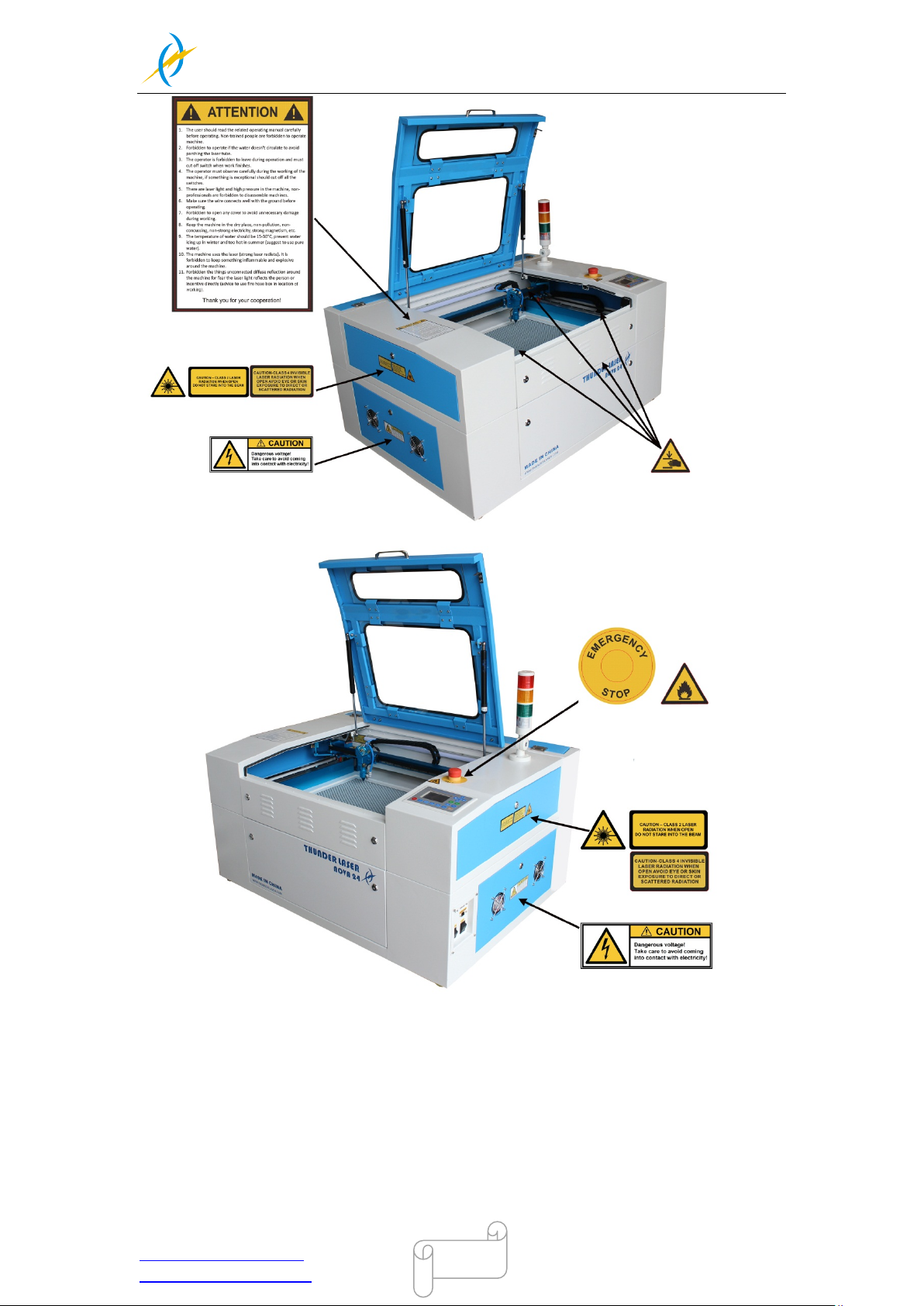
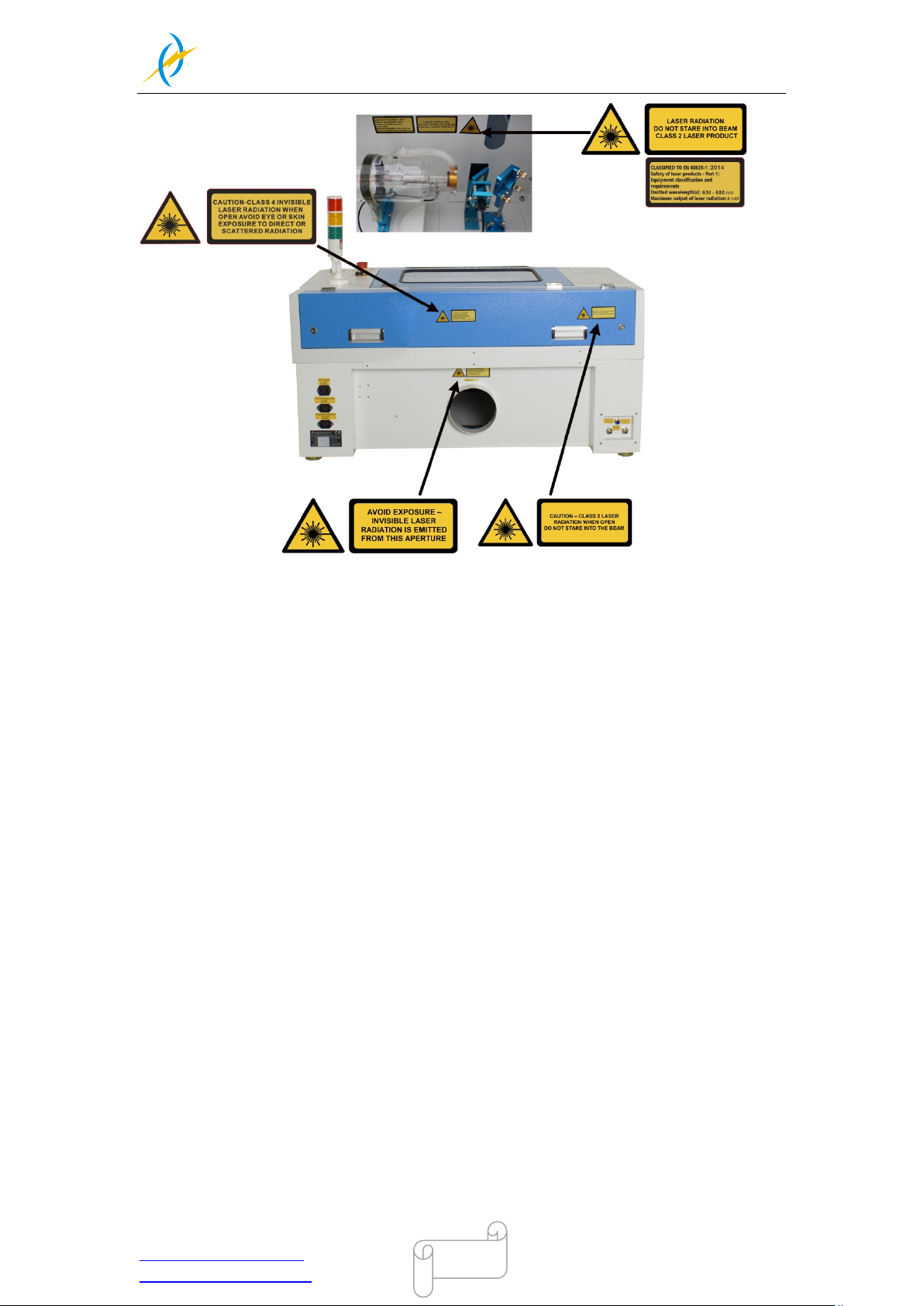
2.4 Warning and Information Labels
The warning and information labels are attached in such positions of
the device that could represent a source of danger during set-up and
operation. Therefore, follow the information on the labels. If labels are
lost or damaged, they must be replaced immediately.
Tel :(86)769 826653
Page 14
THUNDER LASER
NOVA-24
www.thunderlaser.com DONGGUAN THUNDER LASER EQUIPMENT CO.,LTD
[email protected] Shatian Town, Shatian Dadao, Mintian
Dongguan City, Guangdong Province, China
14
Tel :(86)769 826653
Page 15
THUNDER LASER
NOVA-24
www.thunderlaser.com DONGGUAN THUNDER LASER EQUIPMENT CO.,LTD
[email protected] Shatian Town, Shatian Dadao, Mintian
Dongguan City, Guangdong Province, China
15
Tel :(86)769 826653
Page 16

THUNDER LASER
NOVA-24
www.thunderlaser.com DONGGUAN THUNDER LASER EQUIPMENT CO.,LTD
[email protected] Shatian Town, Shatian Dadao, Mintian
Dongguan City, Guangdong Province, China
16
Chapter3 Process of Installing
3.1 Unpacking
You rec eive your T HUNDER LASER NOVA-24 pac ked in a wooden b ox, whic h contains
the laser machine and additional accessories. The following steps give you an overview of
the unpacking and assembly of the laser. Please follow these steps carefully.
Keep the packing box. Y ou will require it in case of a return.
Dispose all waste according to the applicable waste disposal law.
1. Put the wooden box on a flat and spacious room for unpacking.
2. Remove the machine box; carefully remove the foam material, which protects the
viewing window of the cover and around the machine.
3. Take out the key,open the door of the laser,Remove the accessories box which
contains all accessory parts required for the installation of the laser machine.
And check if there’s anything damaged or missed during shipping.
4. You will see an attachment table on the machine; please check whether the
accessories are all on the table.
5. Please keep the keys and the warranty certificate well (and please show us your
warrant y certific ate if you need tec h support for the m achi ne failure, then we will provide
you the best technical service).
6. Remove the sponge and nylon cable ties from inside the machine, and then start to
install the machine (below chapters are installation details)
Tel :(86)769 826653
Page 17
THUNDER LASER
NOVA-24
www.thunderlaser.com DONGGUAN THUNDER LASER EQUIPMENT CO.,LTD
[email protected] Shatian Town, Shatian Dadao, Mintian
Dongguan City, Guangdong Province, China
17
3.2 Location
Before you ins tal l the l as er s ystem, you shoul d s elec t an ap propr i ate loc ati on. Fol l ow the
guidelines shown below:
1. Avoid locations where the system is exposed to high temperatures, dust
and high humidity. (The humidity must not exceed 70% and the temperature
must not be close to the dew point.)
2. Avoid locations, where the system is exposed to mechanical shocks.
1. Breaker protection: Do not connect other devices via the laser breaker, as
the laser system requires the full amperage.
2. DO NOT open any of the machine’s access panels while the unit is plugged in.
Opening a panel may expose the operator to the unit’s AC input power.
3. DO NOT make or break any electrical connections to the system while the
unit is turned on.
1. Avoid locations with poor air circulation; select a location close to
ventilation (if available).Select a location, whose room temperature is
between 15 °C and 25 °C (59° – 77° F).
2. This is fundamental to maintain consistent and reliable operation of a CO2
laser, Metal RF or Glass tube and the machine itself.Avoid higher ambient
temperatures and strong exposure of the engraver to the sun. Use blinds, if
required.
3. Mechanical shock and vibration of the laser will have detrimental effects
on the performance and life expectancy of the machine. It will manifest (over
a period of time) with a noticeable decrease in performance and increased
maintenance required, possibly even damage. Setting your Thunder Laser up
in s suitable temperature controlled, dust free, moisture free, level, stable
surface (a level concrete floor) with the recommended extraction is critical to
the ongoing performance of the machine. It is also a warranty condition.
Tel :(86)769 826653
Page 18
THUNDER LASER
NOVA-24
www.thunderlaser.com DONGGUAN THUNDER LASER EQUIPMENT CO.,LTD
[email protected] Shatian Town, Shatian Dadao, Mintian
Dongguan City, Guangdong Province, China
18
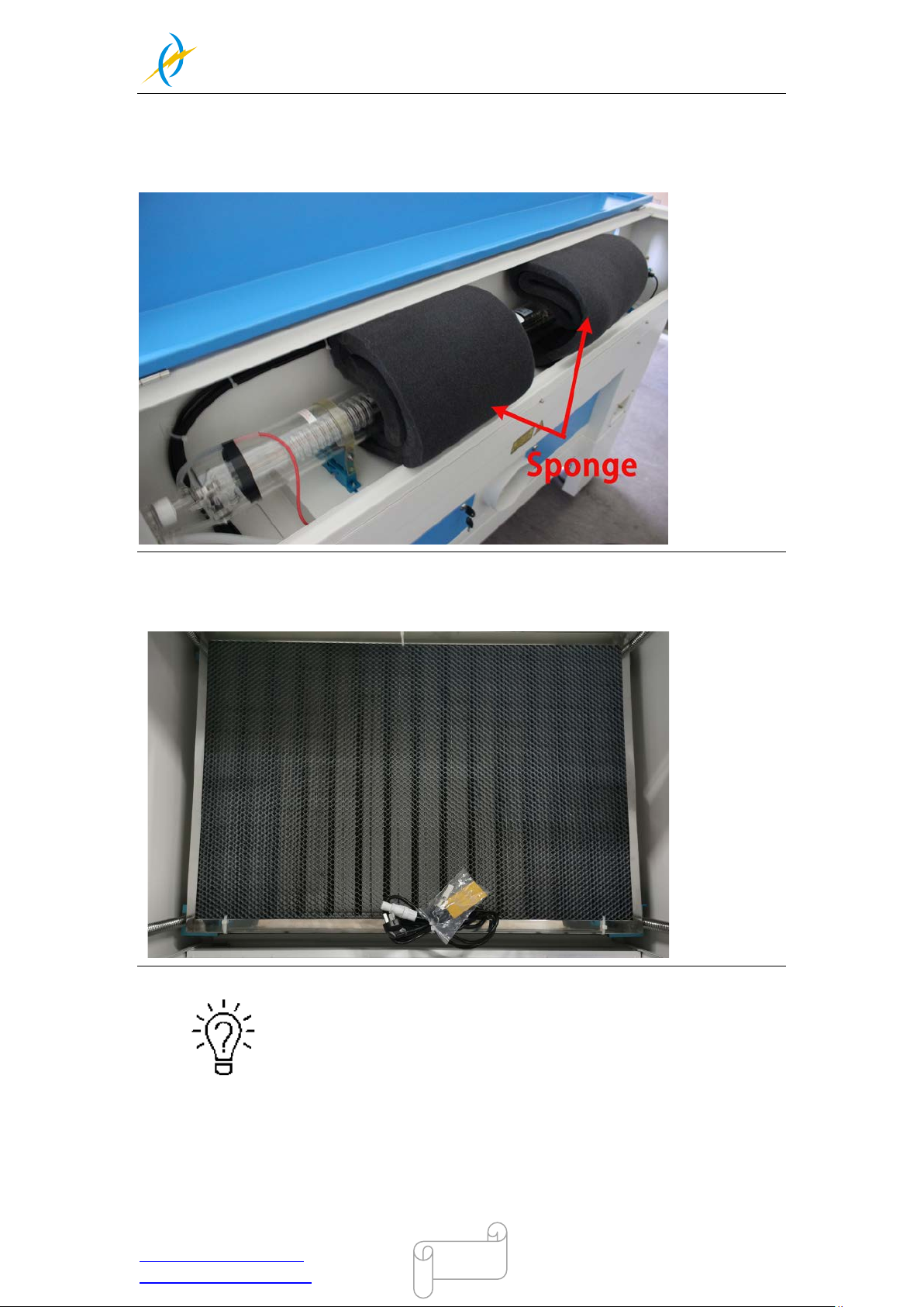
3.3 Before Installation
1. Take out the s ponge around the l aser tube. Like below:
2. Take out the nylon cable ties around the honey comb plate.
Remove t he transparent bag and mains cable out of the front of honey comb
plate, Like below:
The transparent bag has a set of machine door key, USB flash drive, and an
engraving test sample.
The USB flash drive stores software package and the document such as User ’s
Manual and Material Parameters and so on.
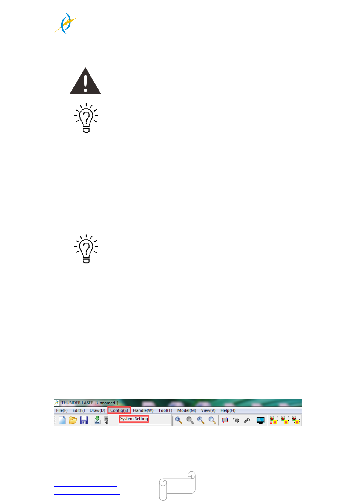
The engraving test sample shows you the setting of “Reverse compensation
setting” for this machine, save those setting by Config(s)>>system
Tel :(86)769 826653
Page 19
THUNDER LASER
NOVA-24
www.thunderlaser.com DONGGUAN THUNDER LASER EQUIPMENT CO.,LTD
[email protected] Shatian Town, Shatian Dadao, Mintian
Dongguan City, Guangdong Province, China
19
setting>>Optimize>>Scanning(Reverse compensation) in your rdworks. so you
can get the better result on scan mode of X_swing.(see the on page for
specifics)
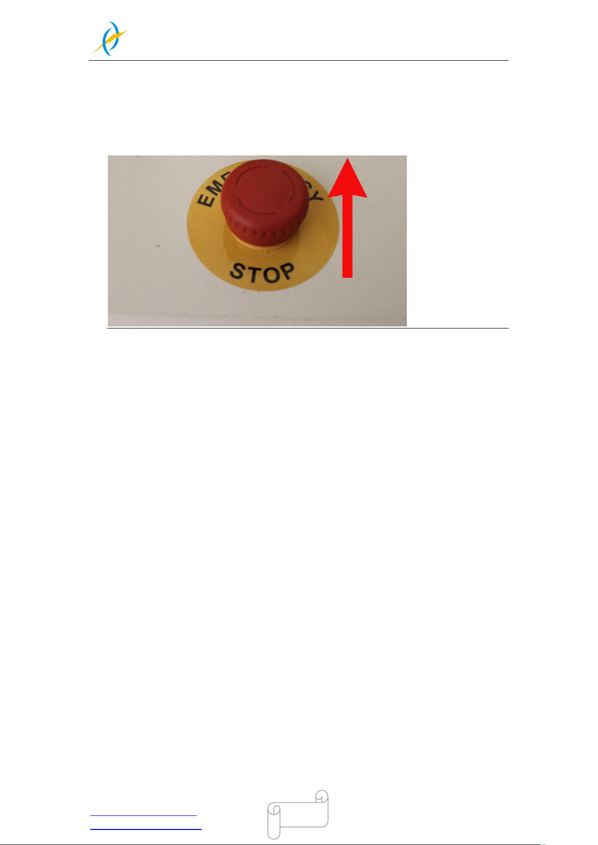
3. Open the emergency switch (mu st do it for the first time to u se the machine).
Like below
Tel :(86)769 826653
Page 20
THUNDER LASER
NOVA-24
www.thunderlaser.com DONGGUAN THUNDER LASER EQUIPMENT CO.,LTD
[email protected] Shatian Town, Shatian Dadao, Mintian
Dongguan City, Guangdong Province, China
20
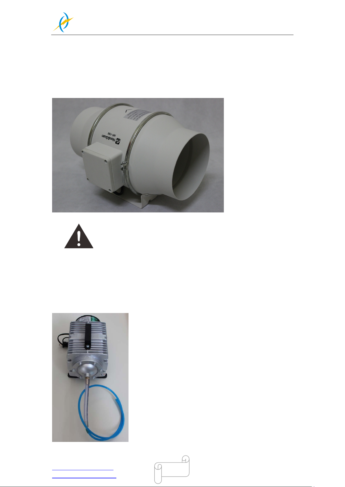
3.4 Exhaust System – Requirements
To guarantee the right ventilation during the engraving and the cutting. The device must
be equipped with a fine exhaust fan(generation of rubber dust), if you use an carbon filter
(neutralization of smells) will be better for exhaust effect. A good exhaust fan of the
outgoing air is also required when cutting plastics or engraving wood.
Connection - see section 3.7.3 connecting the Exhaust System.
Do not start the machine without an adequate exhaust system.
3.5 Air System – Requirements
To guarantee do not catch file and too m uc h smoke duri ng the engr a ving and the cut ting.
The device m ust be connecting with the laser to m ake sure the laser is safe during the
work.
Tel :(86)769 826653
Page 21
THUNDER LASER
NOVA-24
www.thunderlaser.com DONGGUAN THUNDER LASER EQUIPMENT CO.,LTD
[email protected] Shatian Town, Shatian Dadao, Mintian
Dongguan City, Guangdong Province, China
21
Always use the system’s Air Assist feature when vector cutting.
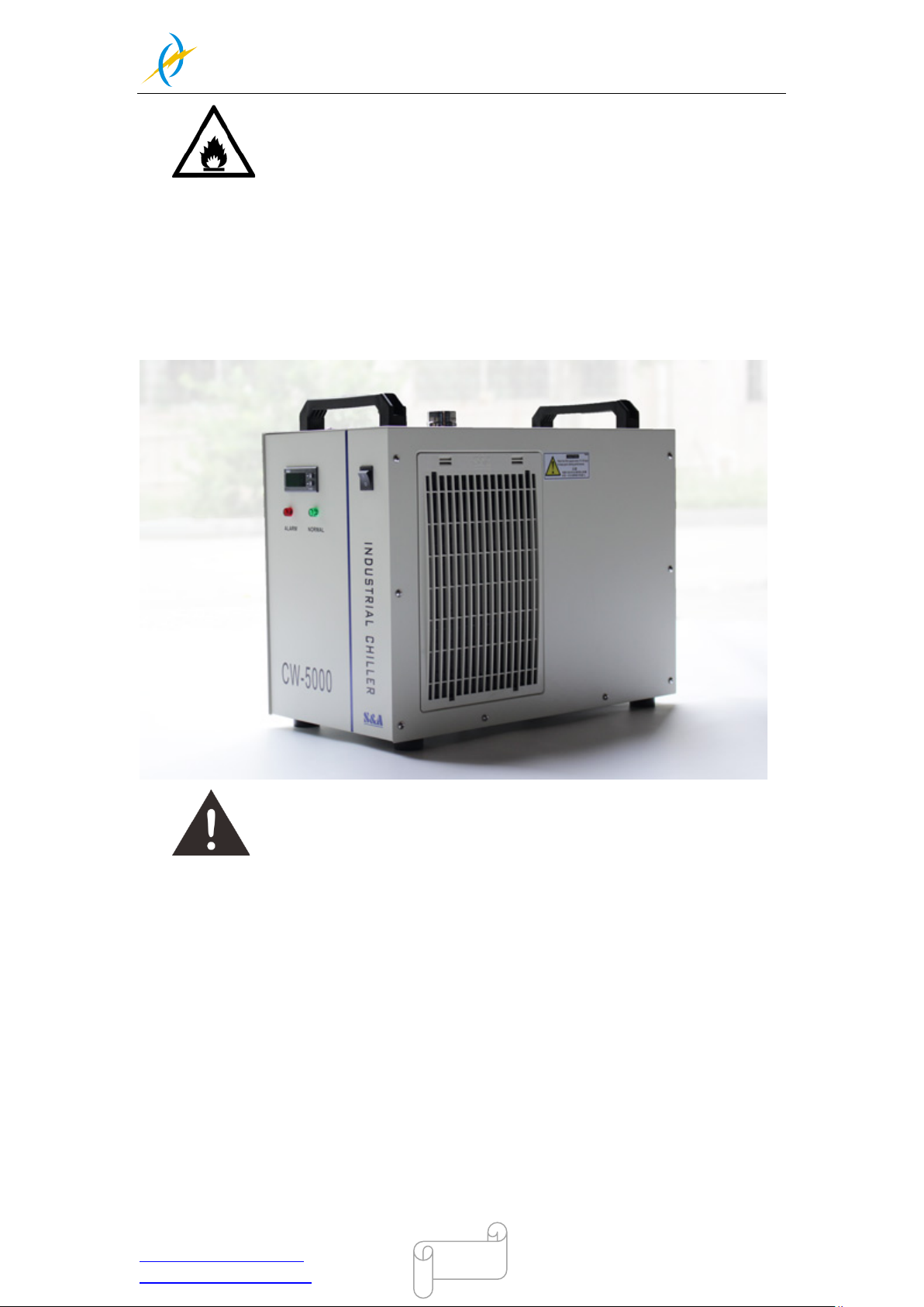
3.6 Water Cooling System – Requirements
To guarantee do not lead to the glass laser tube break once it reach a certain temperature
during the engraving and the cutting. The device must be running and connecting with the
laser to make sure the laser tube is safe during the work.
Do not run the machine without an adequate water cooling system.
Tel :(86)769 826653
Page 22

THUNDER LASER
NOVA-24
www.thunderlaser.com DONGGUAN THUNDER LASER EQUIPMENT CO.,LTD
[email protected] Shatian Town, Shatian Dadao, Mintian
Dongguan City, Guangdong Province, China
22
3.7 Computer – Requirements
The following recommendation represents the minimum requirements. When using a
more powerful computer the graphics are generated and displayed faster and the
computing times and the data transfer to the laser are reduced. To use the newest
software version, you might have to abide other requirements.
• Windows 10 (32 bit or 64 bit )
• Windows 8 (32 bit or 64 bit )
• Windows 7 (32 bit or 64 bit )
Windows Vista (with Service Pack 1 or later)
Windows XP (with Service Pack 2 or later)
• 1024 MB of RAM, 400 MB of hard disk space
• Pentium® 3 or 4 processor or AMD Athlon™ XP
• 1024 x 768 or better monitor resolution
• 1 free USB interface
• 1 free Ethernet interface
• Mouse
Tel :(86)769 826653
Page 23
THUNDER LASER
NOVA-24
www.thunderlaser.com DONGGUAN THUNDER LASER EQUIPMENT CO.,LTD
[email protected] Shatian Town, Shatian Dadao, Mintian
Dongguan City, Guangdong Province, China
23
3.8 Connections
Perform the connections exactly in the order described; otherwise
electrostatic charging can damage your computer and/or the electronics
of the laser system.
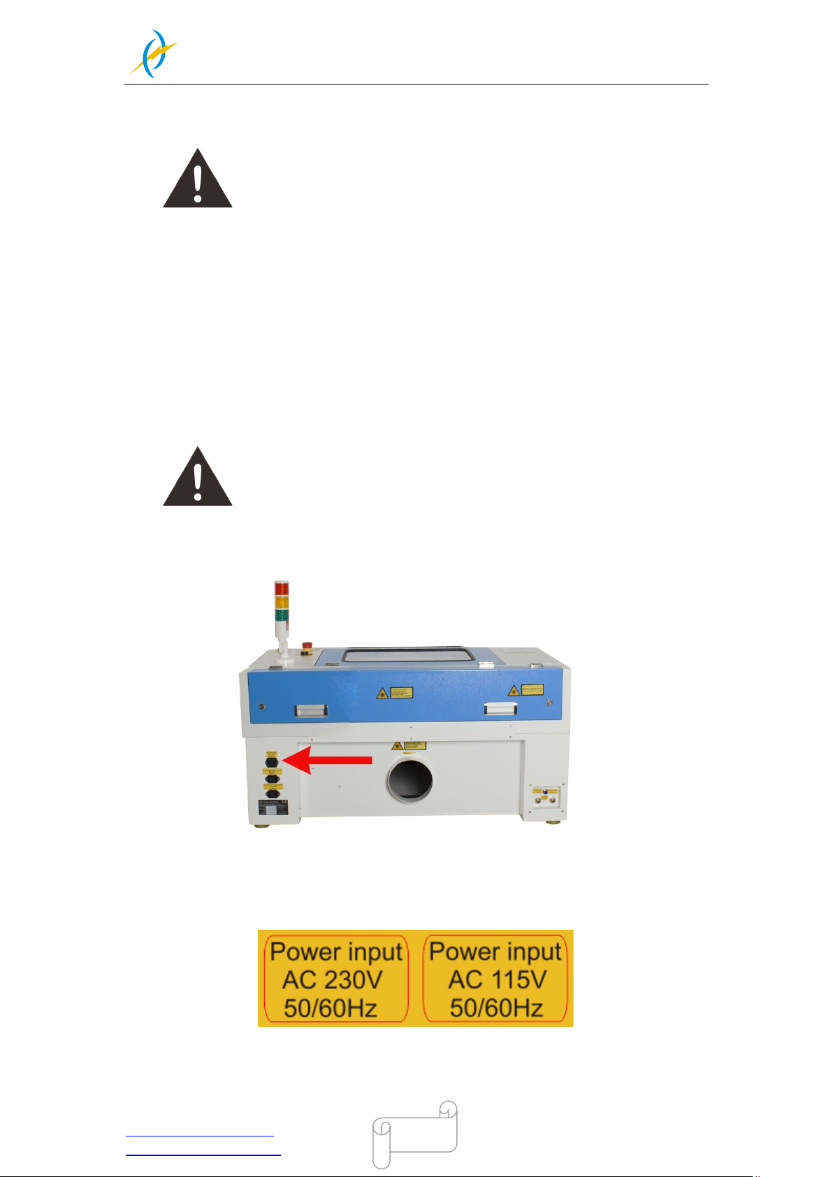
3.8.1 Connecting the Mai ns
Connect one e nd of the m ains cabl e with the connec tion socket at the rear side of the
laser device (see Figure below) and the other end with a protected power outlet.
Mains voltage and opera ting voltage m ust corres pond (AC 230V 50/60 H z o r AC 11 5V
50/60 Hz) – see information label beside the connection socket.
Under no circumstances switch on the device if the voltages do not
correspond.
Tel :(86)769 826653
Page 24
THUNDER LASER
NOVA-24
www.thunderlaser.com DONGGUAN THUNDER LASER EQUIPMENT CO.,LTD
[email protected] Shatian Town, Shatian Dadao, Mintian
Dongguan City, Guangdong Province, China
24
The mains cable is placed the front of the honey comb table.
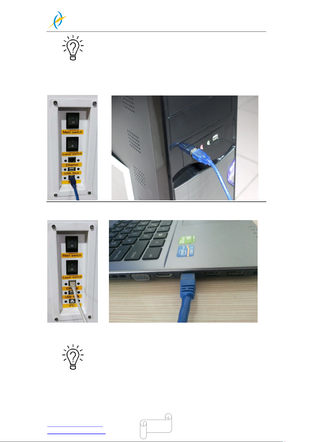
3.8.2 Connecting the Computer
Connecting the Computer and the machine by using the USB cable. Like below:
Connecting the Computer and the machine by using the Ethernet cable. Like below:
The USB and Ethernet cable are placed inside the toolbox.
Tel :(86)769 826653
Page 25
THUNDER LASER
NOVA-24
www.thunderlaser.com DONGGUAN THUNDER LASER EQUIPMENT CO.,LTD
[email protected] Shatian Town, Shatian Dadao, Mintian
Dongguan City, Guangdong Province, China
25
3.8.3 Connecting the Exhaust System
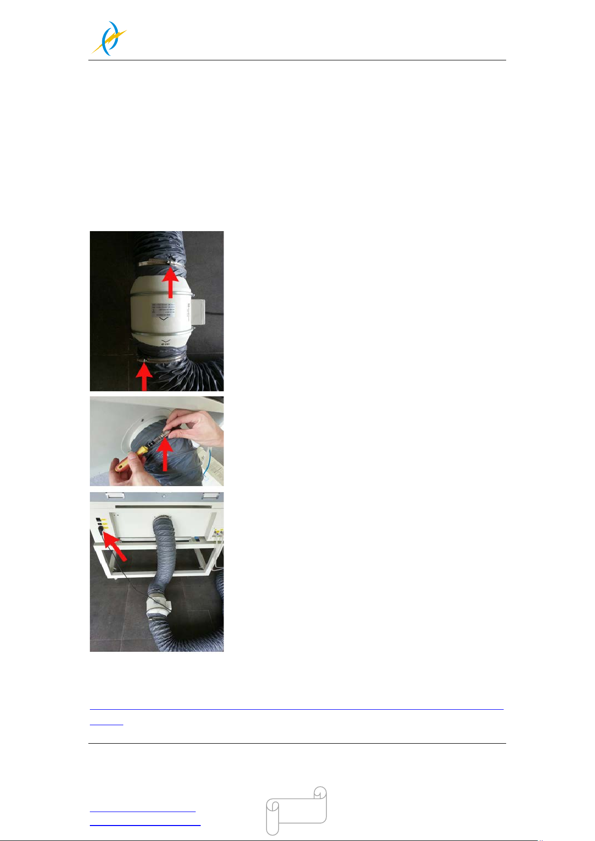
How to set up the exhaust system
Insert one side of the gray exhaust pipe into the fan inlet and the other side into the
fuselage behi nd the exhaust tank. Insert one si de of the gray exhaust pi pe into the fa n
outlet and put the other side of the pipe outside where you work (If the machine is far from
the outside of the r oom that the gas manufactured b y the machi ne cannot be dis char ged;
then you might need an dust/fume filter, it can keep the air quality of your working
environment well).
Please refer to the following pictures about how to install the exhaust pipe:
Also you can refer to the video on how to set up your Nova laser machine in our website
http://www.thunderlaser.com/how-to-use-your-laser-machine/how-to-setup-your-nova-laser-cut
ter.html
Tel :(86)769 826653
Page 26
THUNDER LASER
NOVA-24
www.thunderlaser.com DONGGUAN THUNDER LASER EQUIPMENT CO.,LTD
[email protected] Shatian Town, Shatian Dadao, Mintian
Dongguan City, Guangdong Province, China
26
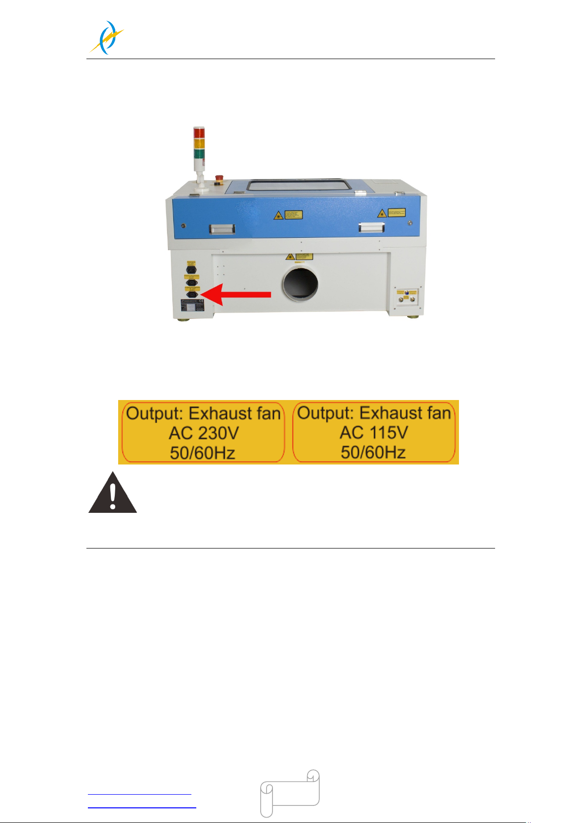
The input voltage must correspond (AC 230V 50/60 H z or AC 115V 50/60 Hz) – see
information label beside the connection socket.
Do not connect the air compressor or the water chiller to the above interface,
if connec t them to the a bo ve inter faces that c ause i n failur e of the m achi ne, th e war ranty
does not covered.
Tel :(86)769 826653
Page 27
THUNDER LASER
NOVA-24
www.thunderlaser.com DONGGUAN THUNDER LASER EQUIPMENT CO.,LTD
[email protected] Shatian Town, Shatian Dadao, Mintian
Dongguan City, Guangdong Province, China
27
3.8.4 Connecting the Air System
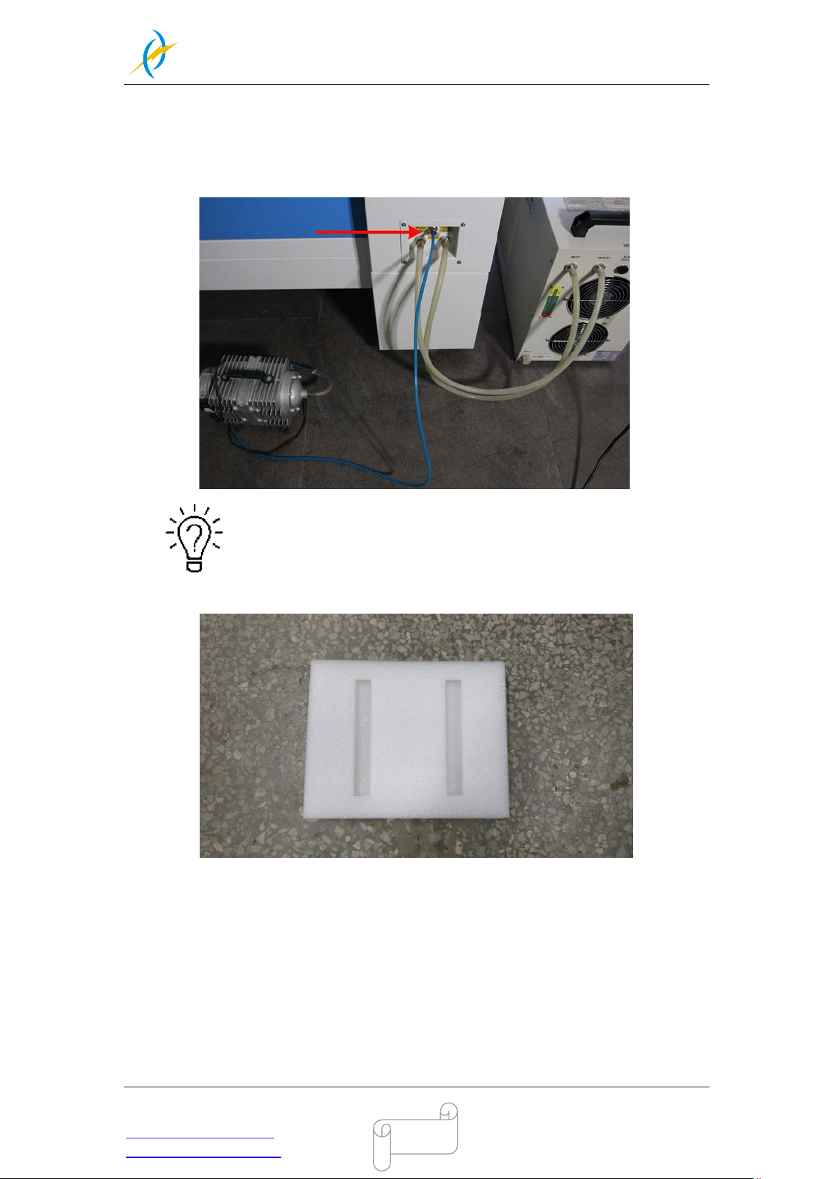
Firs t of all , Install a air bl owing m outh ( copper ) to the air system, then connect the hoses
(white si de) to the mouth, the other side to the machine. Aft er that, pleas e connect the
power cable (of the air system) to the machine. Like below:
A customized anti-shock foam that came with the air pump can be
placed under the air pump.
Tel :(86)769 826653
Page 28
THUNDER LASER
NOVA-24
www.thunderlaser.com DONGGUAN THUNDER LASER EQUIPMENT CO.,LTD
[email protected] Shatian Town, Shatian Dadao, Mintian
Dongguan City, Guangdong Province, China
28
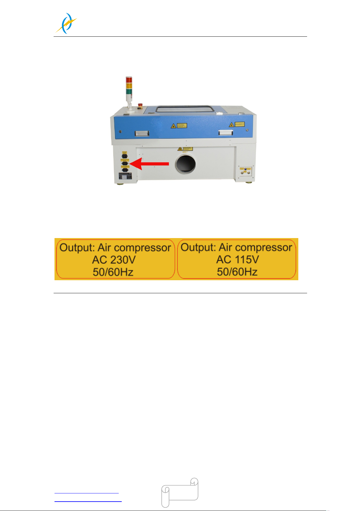
The input voltage must correspond (AC 230V 50/60 Hz or AC 115V 50/60 Hz) – see
information label beside the connection socket.
Tel :(86)769 826653
Page 29
THUNDER LASER
NOVA-24
www.thunderlaser.com DONGGUAN THUNDER LASER EQUIPMENT CO.,LTD
[email protected] Shatian Town, Shatian Dadao, Mintian
Dongguan City, Guangdong Province, China
29
3.8.5 Connecting the Cooling System
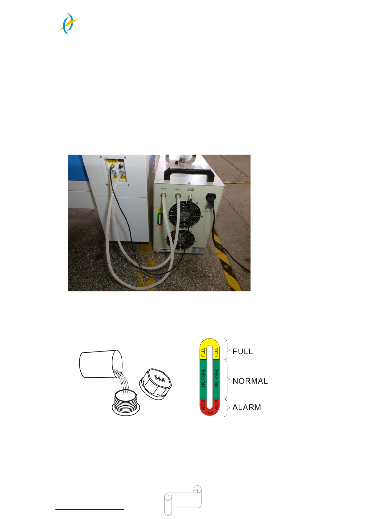
① Open the Toolbox, and then take out the water pipes, water-error signal cable and
chiller power cable.
② One of the water pipes, please connect to the water chiller where marked as
“OUTLET”, the other s ide of t he pi pe connect to the mac hine where mar ked as
“Water IN”.
③ The other pipe, please connect to “ INLE T” of wat er chill er and “W ater OUT” of
machine.
④ The Water-error signal cable, please connect to “ALARM OUTLET” of water
chiller and machine.
⑤ The chiller power cable, please connect to the chiller.
⑥ Add pure(disti lled) water into th e chiller until the water level in the gr een area
showing on the ga uge. Run c hill er for a peri od of time, the water w ill fill into the
laser tube on the machine, please re-add water to keep the water le vel i n the
green area.
Tel :(86)769 826653
Page 30
THUNDER LASER
NOVA-24
www.thunderlaser.com DONGGUAN THUNDER LASER EQUIPMENT CO.,LTD
[email protected] Shatian Town, Shatian Dadao, Mintian
Dongguan City, Guangdong Province, China
30
Chapter4 Operation
4.1 Machine View
Tel :(86)769 826653
Page 31
THUNDER LASER
NOVA-24
www.thunderlaser.com DONGGUAN THUNDER LASER EQUIPMENT CO.,LTD
[email protected] Shatian Town, Shatian Dadao, Mintian
Dongguan City, Guangdong Province, China
31
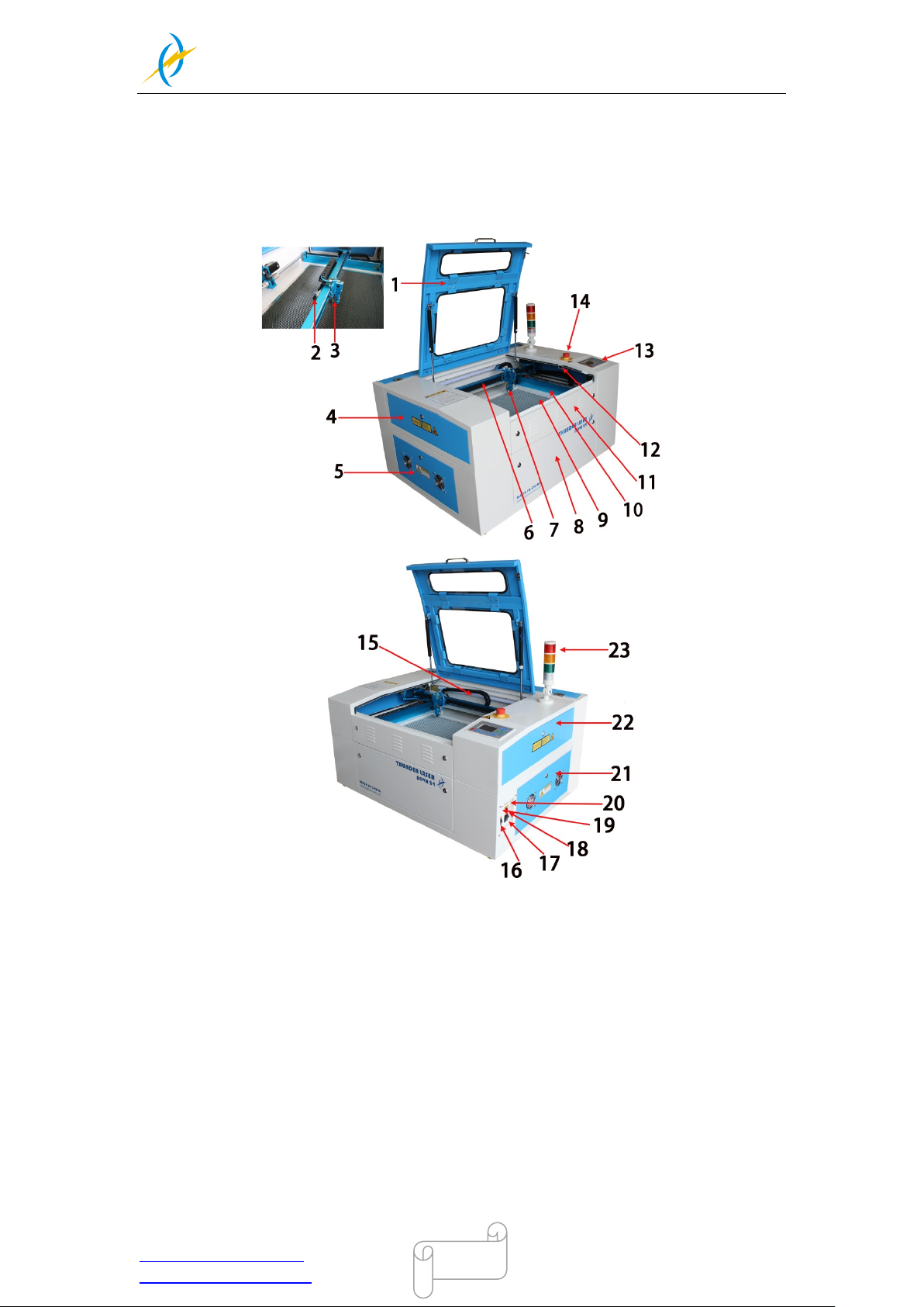
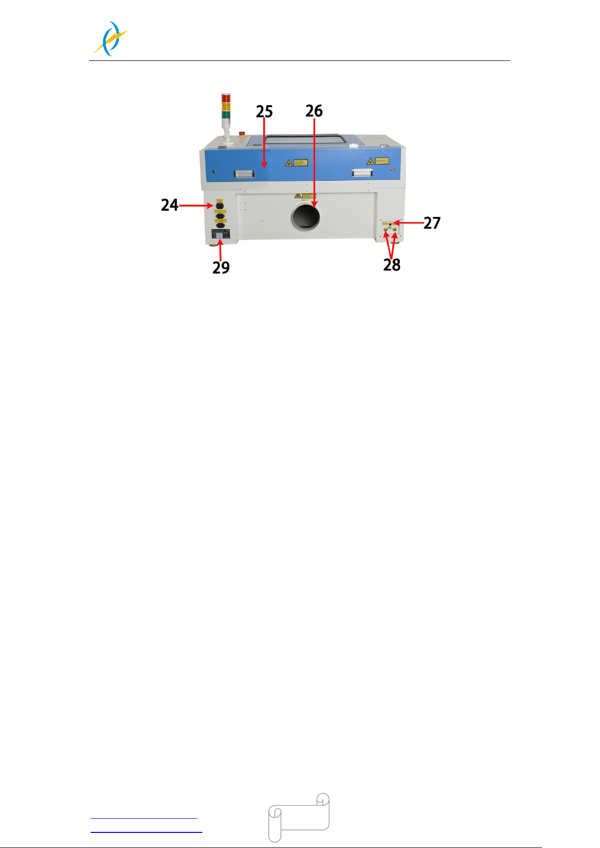
1. Top lid 16. Laser power switch
2. Hand valve Pneumatic Fitting 17. Main power switch
3. Auto focus sensor 18. Ethernet port
4. Left-up side door 19. U-disk connection port(USB)
5. Left side door 20. PC connection port(USB)
6. X-axis 21. Right side door
7. Laser heads 22. Right-up side door
8. Front door 23. Indicate light
9. Honey comb table 24. Power supply socket
10. Y-axis 25. Laser tube cover
11. Front up door 26. Exhaust hose
12. Flap protection sensor 27. Blow air port
13. Control panel 28. Water in and water out
14. Emergency stop switch 29. Manufacturer’s label
15. LED lamp
1. Top lid
If the Top lid is opened, no dat a is pr ocess ed. When t he protec tion co ver is opene d
during working, the motion system is stopped and the laser source is turned off.
During processing of commands the protection cover must only be opened after
pressing the “Pause “button.
2. Hand valve Pneumatic Fitting
It’s used for adjust that blow air amount.
3. Auto focus sensor
Used for the automatic focusing of the work table.
4. Left-up side door
Open this door for cleaning the second reflective mirror or align that laser beam
5. Left side door
Tel :(86)769 826653
Page 32

THUNDER LASER
NOVA-24
www.thunderlaser.com DONGGUAN THUNDER LASER EQUIPMENT CO.,LTD
[email protected] Shatian Town, Shatian Dadao, Mintian
Dongguan City, Guangdong Province, China
32
There is laser power supplier, Ammeter, TL-Timer etc. please open this door for
checking these parts, but must pay attention to the electric current.
6. X-axis
The m otion system is that perform s the mec hanical m ovements i n X directi on. The
X-axis is visible in the working area.
7. Laser head
Laser beam a nd re d dot p ointer ar e all come out from the l aser head, and t he Auto
Focus switch is installed on the laser head, too. The bottom of laser head is parallel to
the bottom of the autofocus switch.
8. Front door
Open this door for cleaning the waste after working.
This door is locked by using two outside locks.
9. Honey comb ta ble
The honey comb pl ate to be proc es sed is put onto the worki ng table. Put the m ater ial
on the working table for engraving & cutting
10. Y-axis
The motion system is that perform s the mechani cal movements in Y direction. The
Y-axis is visible in the working area.
11. Front up door
Open this door for take out the honey comb table and it’s convenient to put that
material on working table
This door is locked by using inside screws and outside locks.
12. Flap protection sensor
This i s where Open flat protection exist. Laser wi ll stop working once the co ver is
opened during working.
13. Control panel
You can control the X-axi s , Y-axis and Z -axis manual ly by the dis play panel, it also
shows the wor king ti m e, power, speed and the w hol e wor king ti m e and a ffords m an y
function options(please view this chapter 4.3 for detail).
14. Emergency stop switch
Once there’s an ac c ident ha ppen ( las er catc h fi re, l aser out l eakage) duri ng w or king,
please turn off t his switc h immediatel y. It wil l be cut off the las er power and m otion
power immediately.
15. LED lamp
It’s used for lighting the working table once turn the Main switch on.
16. Laser power switch
Tel :(86)769 826653
Page 33

THUNDER LASER
NOVA-24
www.thunderlaser.com DONGGUAN THUNDER LASER EQUIPMENT CO.,LTD
[email protected] Shatian Town, Shatian Dadao, Mintian
Dongguan City, Guangdong Province, China
33
The laser power will be on while you turn it on
17. Main power switch
The laser machine will be start while you turn it on
18. Ethernet port
This Ethernet port is for connecting computer.
19. U-disk connection port(USB)
You can sa ve the fil e as a U-disk Fi le b y press “SaveToUFile” on the s oftwar e, then
save it to the u-di sk and insert the u-disk to the port of las er machine, then use the
control panel to select and control it to work
20. PC connection port(USB)
This USB is for connecting computer.
21. Right side door
There are laser controller, driver(Hybrid Servo Drive and Micro Stepper Drive ),
power suppl iers ( both 24 v DC and 36vDC), the mai n connecti ng cables and cooli ng
fan here, please open this door for checking these parts, but must pay attention to the
electric current. if you need to repair, please c ontact with professi onal maintenanc e
staff.
22. Right-up side door
Maintenance for the Emergency stop button if required
This door is locked by using outside locks.
23. Indicate light
The light is always keeping green c olor whi le the laser does not work or worki ng but
the lid is closed.
The light will turns to red color while the lid/cover is opened during working.
24. Laser supply socket
To connect the main power and the extend power according the label information. And
in the main power socket have the fuses.
25. Laser tube cover
There are installed the laser tube, red dot pointer device, beam combiner and the first
reflective mirror mount.
26. Exhaust hose
This is for installing the exhaust device.
27. Blow air port
This port is for connecting hoses of the air compressor.
28. Water in and water out
Tel :(86)769 826653
Page 34

THUNDER LASER
NOVA-24
www.thunderlaser.com DONGGUAN THUNDER LASER EQUIPMENT CO.,LTD
[email protected] Shatian Town, Shatian Dadao, Mintian
Dongguan City, Guangdong Province, China
34
Both ports are for connection with water pump or water chiller.
29. Manufacture’s Label
It’s Show you the laser information like serial number or manufacturing date etc.
Tel :(86)769 826653
Page 35
THUNDER LASER
NOVA-24
www.thunderlaser.com DONGGUAN THUNDER LASER EQUIPMENT CO.,LTD
[email protected] Shatian Town, Shatian Dadao, Mintian
Dongguan City, Guangdong Province, China
35
4.2 ON/OFF Switch
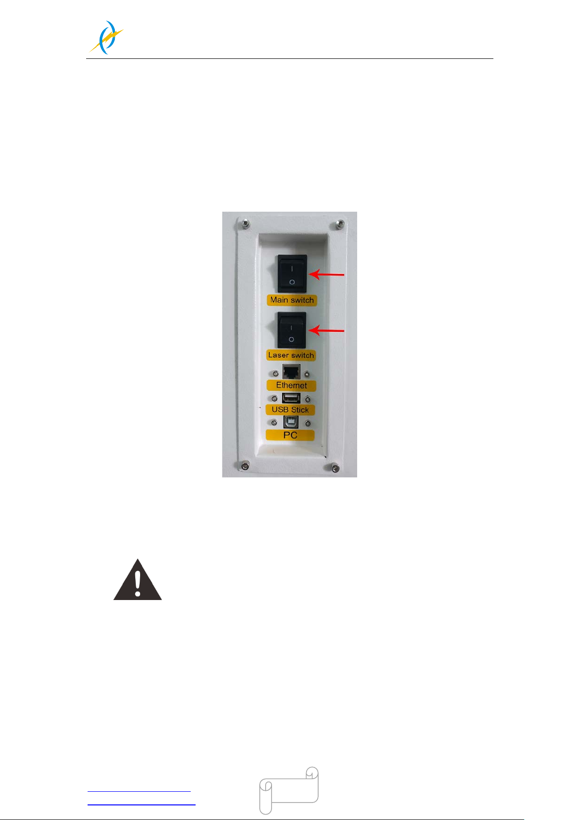
The mains and the laser supply power ON/OFF switch
The following conditions must be fulfilled for correct start up:
Unrestricted freedom of motion of the mechanics
No materials under the engraving table
Protection covers closed
When tur n on the power of machine, and note that turn on the m ai n sw itc h fi rst and the n
the laser supply power switch
If all covers are closed, immediately after being switched on, the device starts the
referenci ng process. When the referencing pr ocess is completed correctly, a n acoustic
signal sounds and the de vice is ready for operati on. The oper ation panel w ill displ ay the
home screen when the laser is completed resets.
Before switching on the device, the user must make sure that no objects
of any kind are located inside the operating space, which could limit or
obstruct the mechanics of the device.
Tel :(86)769 826653
Page 36
THUNDER LASER
NOVA-24
www.thunderlaser.com DONGGUAN THUNDER LASER EQUIPMENT CO.,LTD
[email protected] Shatian Town, Shatian Dadao, Mintian
Dongguan City, Guangdong Province, China
36
4.3 How to setup the software
4.3.1 Software installation
Your machine comes with a USB flash drive, which you will find many helpful application
videos and instructions as well as the software for your machine.
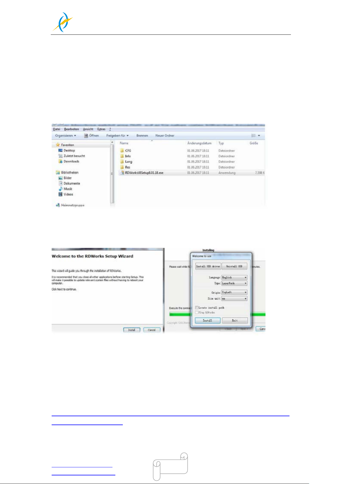
To install the software, insert the USB flash drive into your PC and open the "Software"
folder on the USB flash drive.
In this folder you will find the installation file "RDWorksV8Setup8.01.43.exe". Run this file
by double-c l icking on your PC.
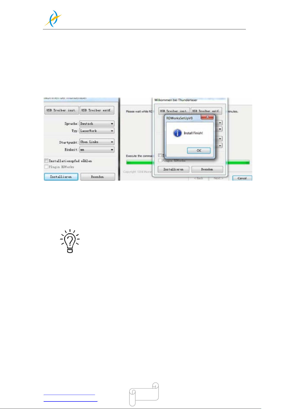
Follow the installation menu until the window "Welcome to use" opens, like below.
If you use USB cable connection,please install the USB driver.
The type of the program offers different possibilities:
1. LaserWork: If you select this option, the laser software RDworksV8 will be installed on
your computer.
2.CorelDraw_Laser: If you work a lot with Corel Draw, you can transfer your images and
drawings directly to RDworksV8.
How to install the coreldraw plugin for RDworksV8, click below link for instruction
https://www.thunderlaser.com/troubleshooting/software-problem/how-to-install-the-coreldr
aw-plugin-for-rdworks.html
3. AutoCAD_Laser: Select this option to install a plugin that can transfer the drawings
directly from AutoCAD to RDWorksV8.
Tel :(86)769 826653
Page 37
THUNDER LASER
NOVA-24
www.thunderlaser.com DONGGUAN THUNDER LASER EQUIPMENT CO.,LTD
[email protected] Shatian Town, Shatian Dadao, Mintian
Dongguan City, Guangdong Province, China
37
4. EngraveLab_Laser: Select this option and install a plugin that can transfer the drawings
directly from EngraveLab to RDWorksV8.
Origin (zero point): This is specified by the machine and must always be selected "top-left"
for Thunderlaser machines.
Size unit: Here you can choose between millimeters and inches.
Select installation path: Here you can select a different installation directory for your laser
software. We recommend that you use the default settings, otherwise some operating
systems may restrict the functionality of the software due to misinterpreted access rights.
After selecting your options, click "Install" and then brings up a window "Install Finish!”.
You can confirm this and then end the installation process.
A "RDWorksV8" icon will be automatically added to your Desktop, you are now ready to
use the RDworksV8.
Trouble shooting for RDworks installation.
If you were unable to install the RDworks,it’s possible that your
Anti-Virus software is blocking installation.
Please disable all Virus and Spyware Protection Features. After the
RDwroksV8 has been installed go back into your Anti-Virus software
and re-enable the setting that was disabled.
Tel :(86)769 826653
Page 38
THUNDER LASER
NOVA-24
www.thunderlaser.com DONGGUAN THUNDER LASER EQUIPMENT CO.,LTD
[email protected] Shatian Town, Shatian Dadao, Mintian
Dongguan City, Guangdong Province, China
38
4.3.2 Make connection between PC and machine
USB cable connection
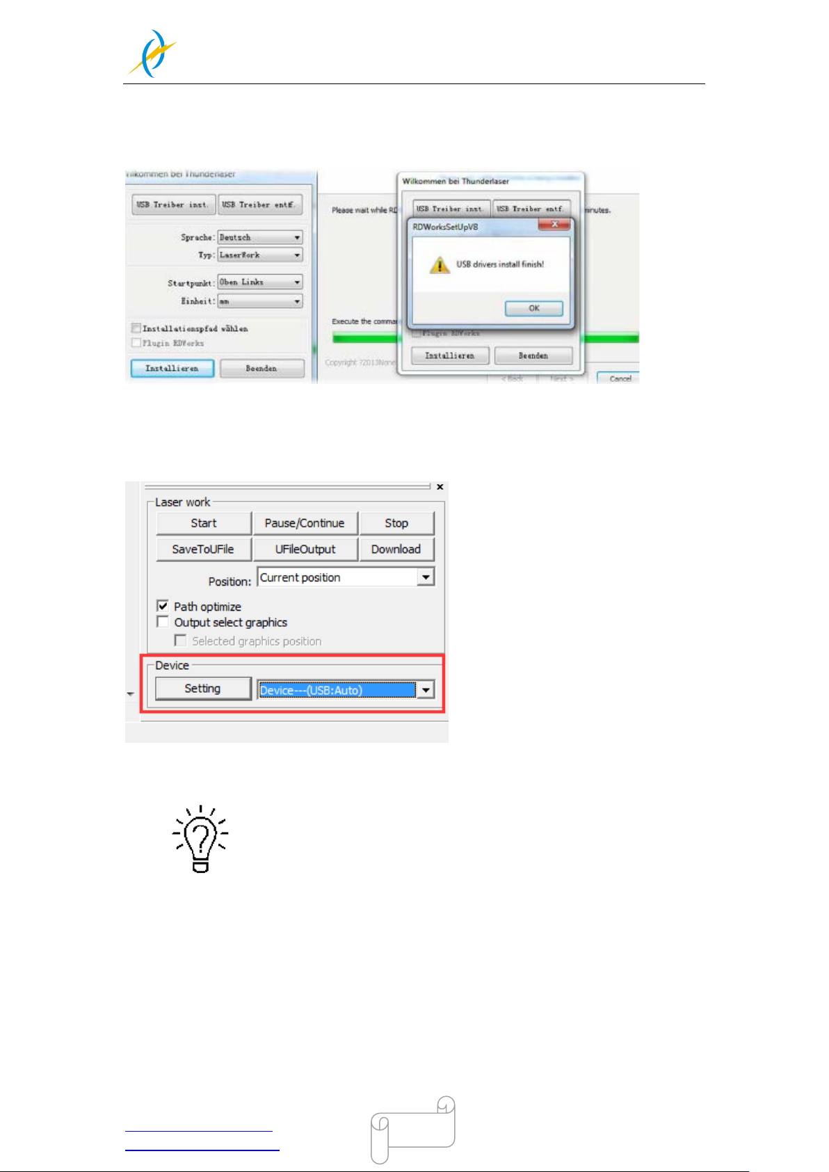
Make sure that you have the USB driver installed during the installation process.
Make sure that you have your PC connected to the machine via USB cable,
Open RDworks, from right bottom corner of the software, set up the Device by
Setting>>Device --- (USB: Auto).
Your PC is now connected to the machine.
When connecting the machine and the PC for the first time, it may take
a few minutes for the operating system to recognize the machine and
install the driver.
Tel :(86)769 826653
Page 39
THUNDER LASER
NOVA-24
www.thunderlaser.com DONGGUAN THUNDER LASER EQUIPMENT CO.,LTD
[email protected] Shatian Town, Shatian Dadao, Mintian
Dongguan City, Guangdong Province, China
39
Ethernet cable connection
Make sure that you have your PC connected directly to the machine via Ethernet cable,
The machine is already assigned an IP address when delivered:
192.168.1.100
Now set up your PC so that it is in the same network and can communicate with the
machine.
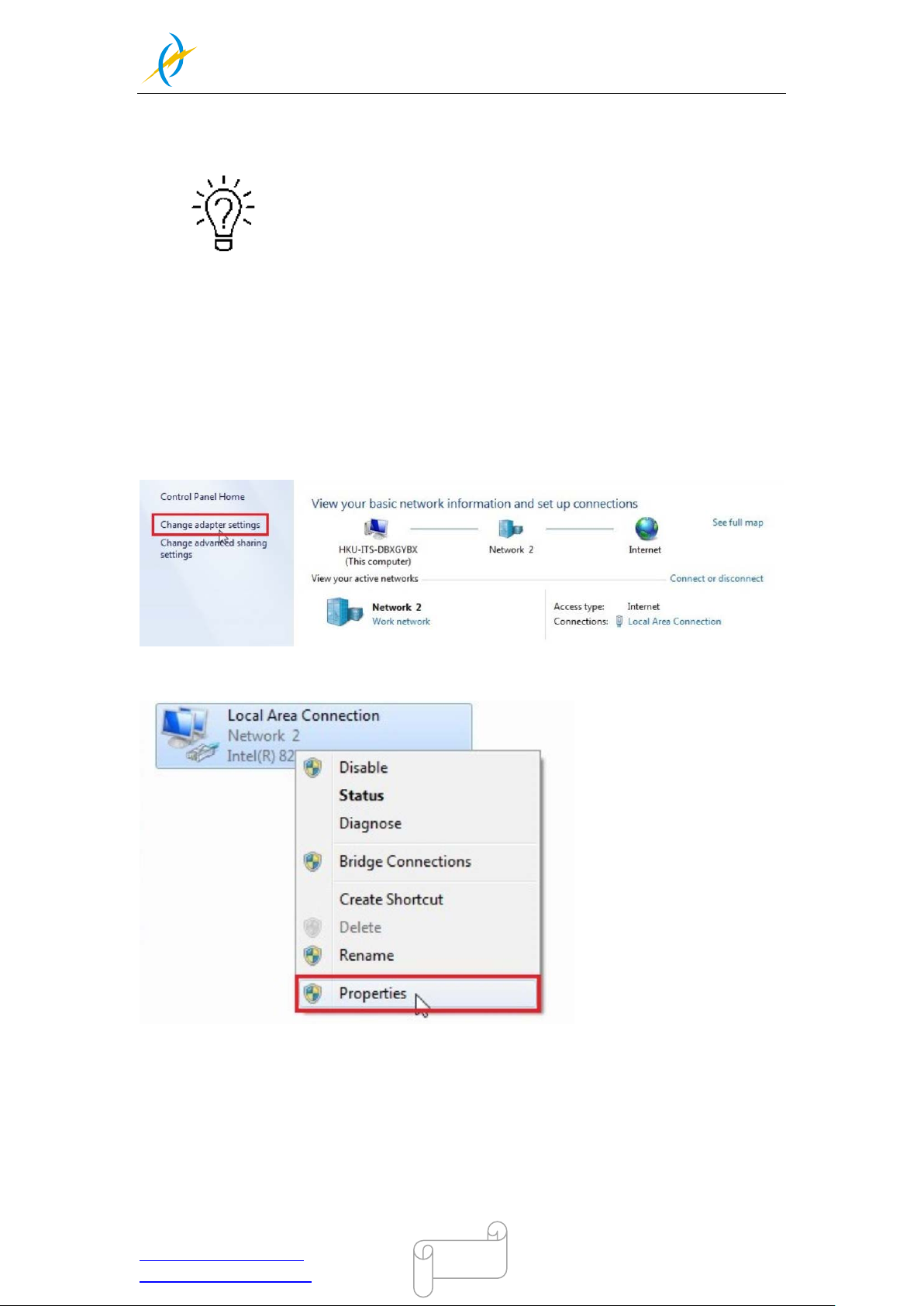
Please follow the instructions below for the setup process (For Windows7):
1). Click Windows Start > Control Panel.
2). Click Network and Internet > Network and Sharing Center. In the left pane,
click Change adapter setting.
3).Right click Local Area Connection and then select Properties.
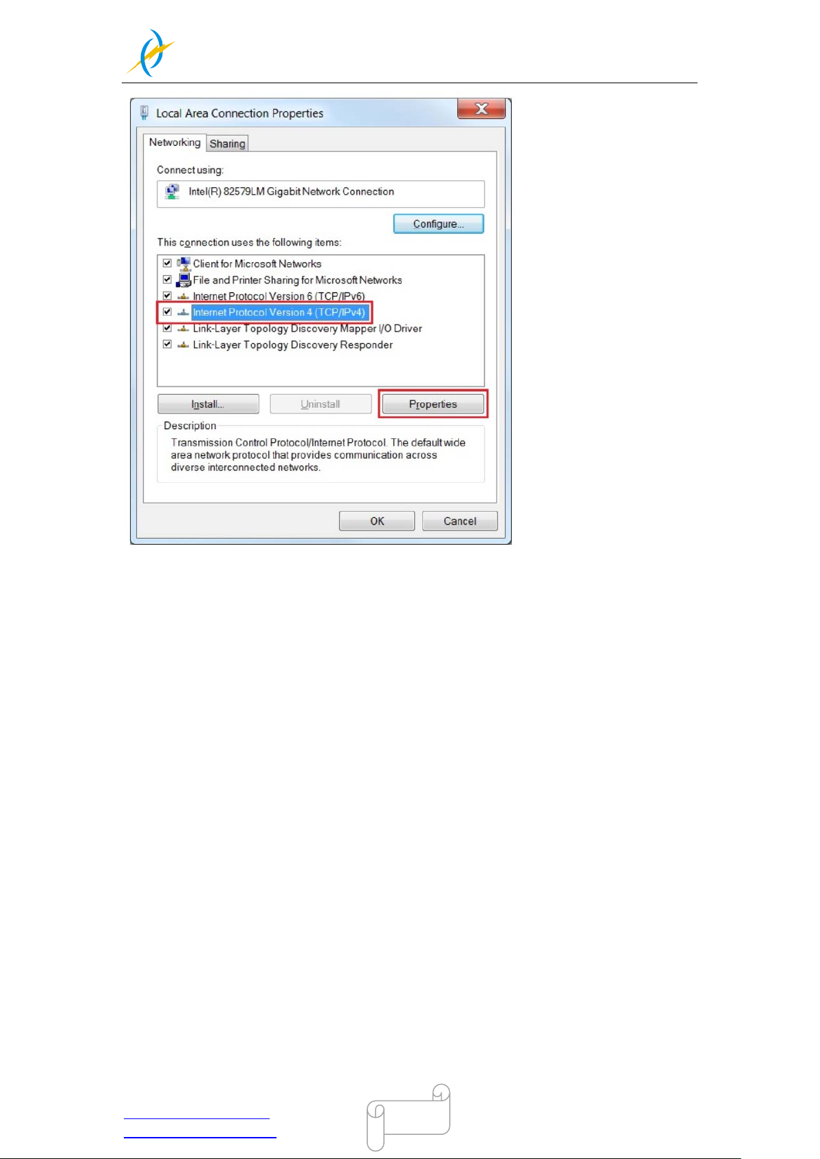
4). Under Networking tab, choose Internet Protocol Version 4 (TCP/IPv4) and then
click Properties
Tel :(86)769 826653
Page 40
THUNDER LASER
NOVA-24
www.thunderlaser.com DONGGUAN THUNDER LASER EQUIPMENT CO.,LTD
[email protected] Shatian Town, Shatian Dadao, Mintian
Dongguan City, Guangdong Province, China
40
5). In "Internet Protoc ol Version 4 (TCP /IPv4) Prop er ties" window, Select "Use t he following IP
address:"
Type IP Address : 192.168. 1.1
And Type subnet mask : 255.255.2 55. 0
Then click OK.
With this you have succes sfully created the prerequisites so that the machine and the PC can
comm unicate via LAN.
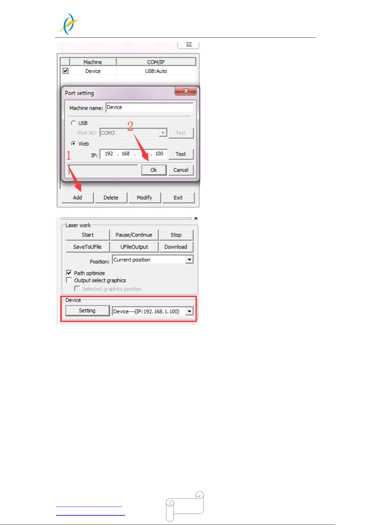
Now open your RD Works from ri ght bott om corner of the softwar e, set up the Device by
Setting>>Device --- Add a “Device---(IP:192.168.1.100)”.
Tel :(86)769 826653
Page 41
THUNDER LASER
NOVA-24
www.thunderlaser.com DONGGUAN THUNDER LASER EQUIPMENT CO.,LTD
[email protected] Shatian Town, Shatian Dadao, Mintian
Dongguan City, Guangdong Province, China
41
Now RDWorks commun icates with your laser machine via LAN.
Tel :(86)769 826653
Page 42
THUNDER LASER
NOVA-24
www.thunderlaser.com DONGGUAN THUNDER LASER EQUIPMENT CO.,LTD
[email protected] Shatian Town, Shatian Dadao, Mintian
Dongguan City, Guangdong Province, China
42
4.4 How to use the display
4.4.1 Function of the Buttons
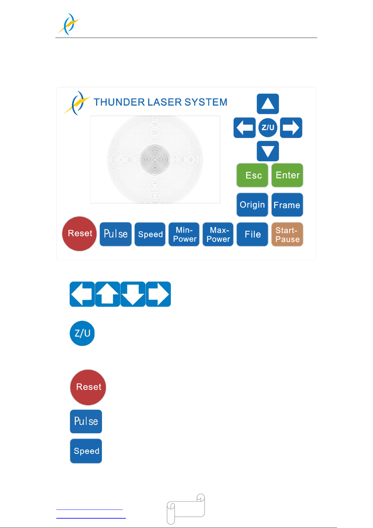
Arrow buttons: control the movement of the laser
head.(also can be used to change the parameters in the control panel)
Z/U button: The Z/U key can be pressed when the system is idle or the work
is finished. On pressing this key, it will show some entries in the interface, each entry
includes some functions, Z axes move, U axes move, each axes to go home etc.
Reset button: Reset the machine.
Pulse button: Pulse a laser beam.
Speed button: Set the speed of the current running layer, or set the arrow
buttons’ move speed.
Tel :(86)769 826653
Page 43
THUNDER LASER
NOVA-24
www.thunderlaser.com DONGGUAN THUNDER LASER EQUIPMENT CO.,LTD
[email protected] Shatian Town, Shatian Dadao, Mintian
Dongguan City, Guangdong Province, China
43
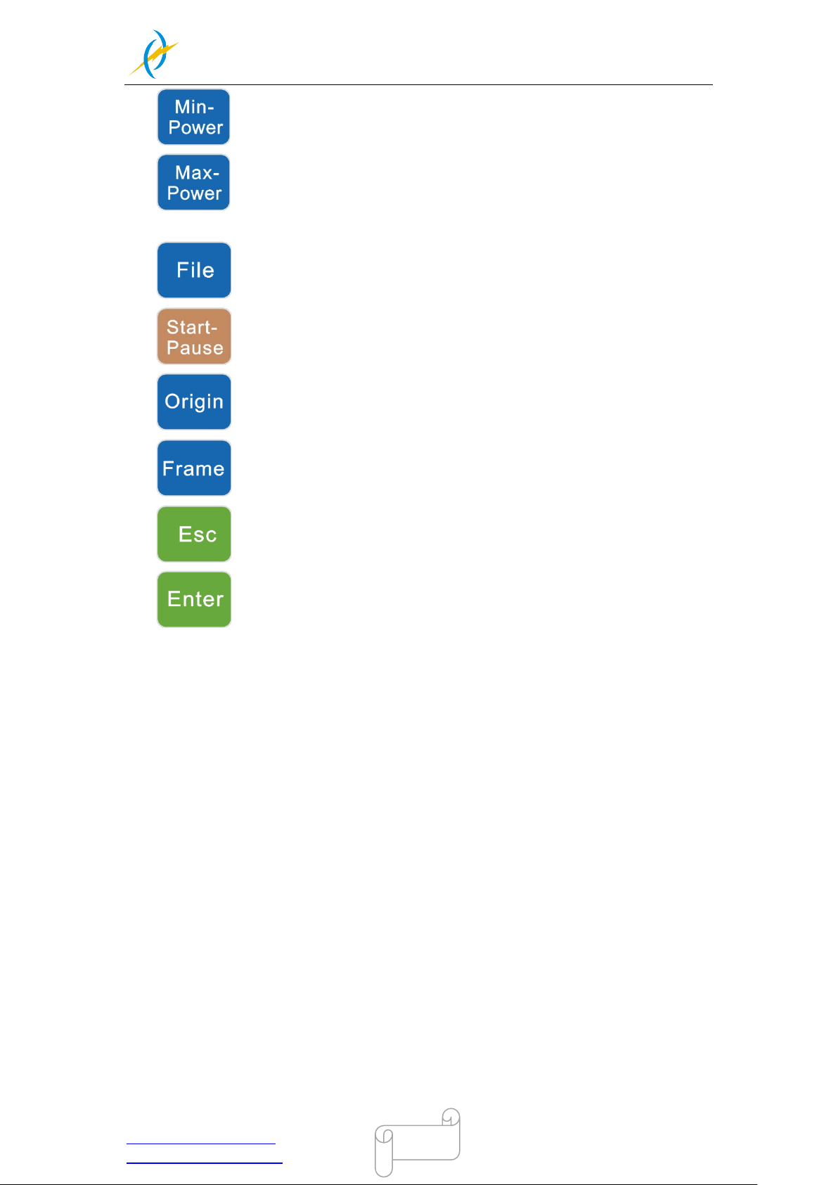
Min-Power button: Set the min laser power of the current running layer.
Max-Power butto n: Set the max laser power of the current running layer,
or set the power of “pulse” button.
File button: The management of the memory and U disc files.
Start-Pause button: run/pause the current job.
Origin button: set the starting point for the laser head.
Frame button: To track by the current file’s frame.
Esc button: To stop work, or return to the last menu.
Enter button: confirm your selection.
Tel :(86)769 826653
Page 44
THUNDER LASER
NOVA-24
www.thunderlaser.com DONGGUAN THUNDER LASER EQUIPMENT CO.,LTD
[email protected] Shatian Town, Shatian Dadao, Mintian
Dongguan City, Guangdong Province, China
44
File
:
Speed
:
MaxPow :
01
300mm
/s
30
.0
%/
30.
0
%
X:
Y
:
Z
:
150.2
153
.5
3000
mm
mm
mm
01 400 25
.0
02 200 29.
1
03 100 31
.5
Idle
00
.00
.
00 Count: 99 X : 180.5 mm Y: 235
.
6 mm
connect
Graph display
area
Graph layer
parameters
Running
Status
Working
Number
Running
parameters
Net Status
File dimension
Coordinate
Running
progress bar
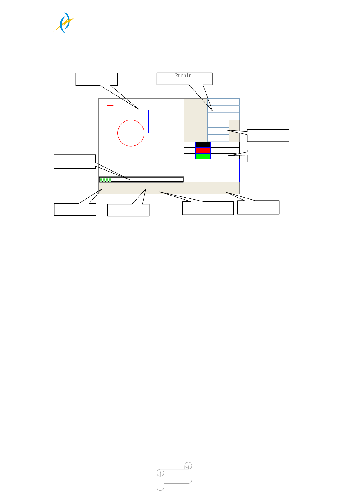
4.4.2 The main interface
When the system is powered on, the screen will show as below:
When work is Idle or finished, all buttons can be clicked, users can select a file to run, set
some parameters, preview to a select file etc. But, when work is running or paused, some
buttons don’t respond when they are clicked.
Tel :(86)769 826653
Graph Display Area: To display the whole file’s track, and display the running
track.
Running parameters: T o display the running file’s file number, speed, max power
etc.;
Coordinate: To display the current coordinate of X,Y and Z axes
Graph layer parameters: To display the layers’ information of the current file,
such as max or min power, speed etc.. When system is idle, dblclick the layer,
then users can change the layer’s parameters and the changing would be
saved.
Running Status: T o display the current status of the machine, such as Idle, Run,
Pause, Finish, etc.;
Running Progress Bar: To display the progress bar of the current running file;
Working Number: To accumulate the work number of the current file.
File Dimension: To display the dimension of the current file;
Net status: To display the connecting status of the Ethernet.
Page 45
THUNDER LASER
NOVA-24
www.thunderlaser.com DONGGUAN THUNDER LASER EQUIPMENT CO.,LTD
[email protected] Shatian Town, Shatian Dadao, Mintian
Dongguan City, Guangdong Province, China
45
Speed:
mm/s
Modified press Enter
300
%
Modified press Enter
%
MaxPower1:
MaxPower2:
30.0
30.0
Press Z/U move item
02 200 29.1
03 100 31.5
01 400 25.1
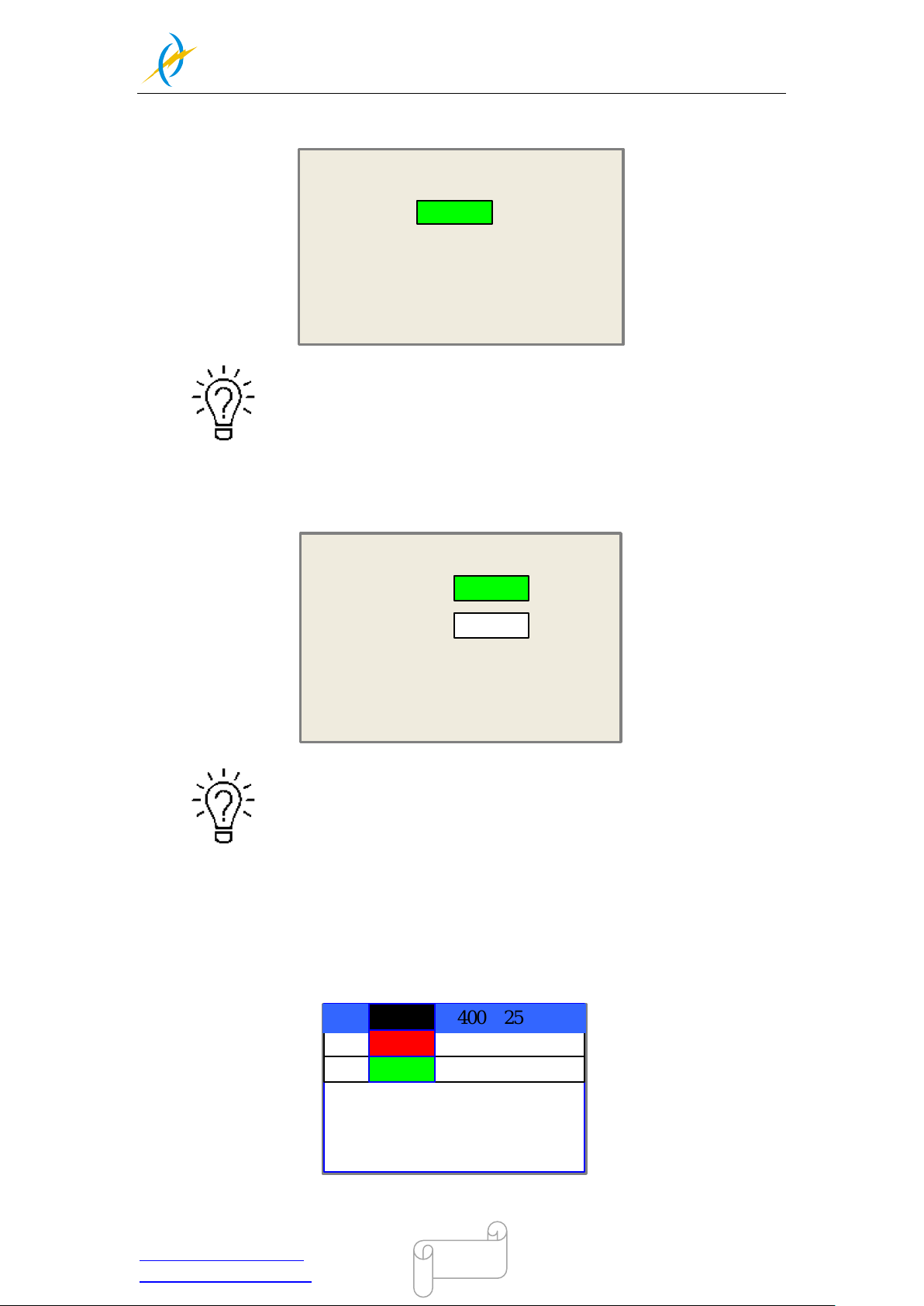
4.4.3 Speed button
The speed can be set from 1~1000mm/s.
4.4.4 Max Power buttons
4.4.5 Set the Layer Parameters
After selec ting a file to preview on the main inter face, user can click “Enter” button to
modify the parameter for the file from the machine.
The max power can set the power for pulse button to shoot the laser
beam,and max power2 is only for the double laser tube machine.
Tel :(86)769 826653
Page 46
THUNDER LASER
NOVA-24
www.thunderlaser.com DONGGUAN THUNDER LASER EQUIPMENT CO.,LTD
[email protected] Shatian Town, Shatian Dadao, Mintian
Dongguan City, Guangdong Province, China
46
MaxPower1:
%
Modified press Enter
30.0
MaxPower2:
Press Z/U move item
%
30.0
Layer0:
MinPower1:
%
22.0
MinPower2:
%
30.0
Speed
:
mm/s
400
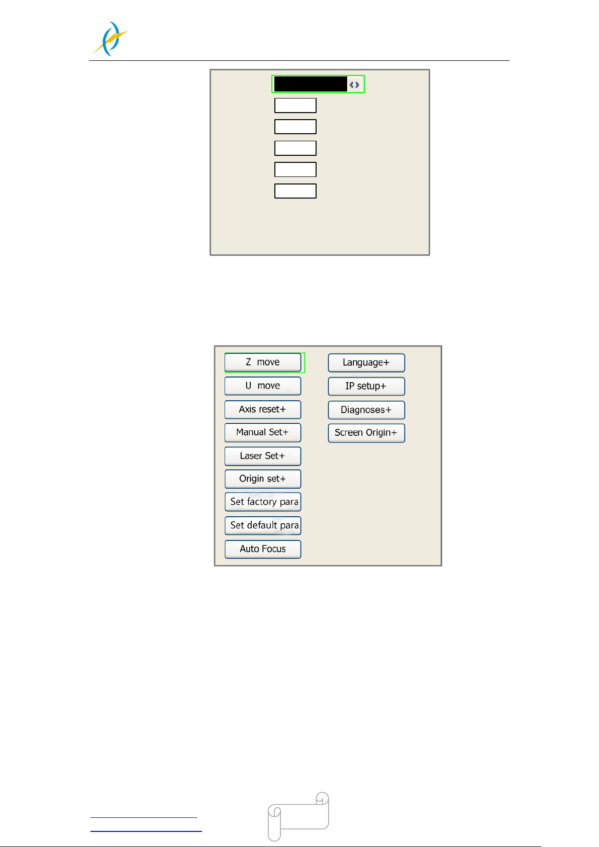
4.4.6 Z/U button
The Z/U button can be pressed when the system is idle or the work is finished. On
pressing this button, it will show some entries in the following interface:
Z Move: When the green block is on “Z Move” item, to move the Z-axis table up
and down by pressing left and right arrow button.
U Move: When the green block is on “U Move” item, to control the rotary
attachment to turn by pressing left and right arrow button.
Axis Reset+: When the green block is on this item, you can manually reset the
axis if needed.
Set defaul t para: To recover all manufac turer param eters and us er param eters
for your machine
Auto Focus: To use the auto focus function.
Language: The item “Language” helps you to select a appropriate langue which
is displayed on the panel:
IP Setup: The machine is already assigned an IP address as 192.168.1.100,and
the IP address on software should be the same while communicate
Tel :(86)769 826653
Page 47
THUNDER LASER
NOVA-24
www.thunderlaser.com DONGGUAN THUNDER LASER EQUIPMENT CO.,LTD
[email protected] Shatian Town, Shatian Dadao, Mintian
Dongguan City, Guangdong Province, China
47
Diagnoses: the “Diagnoses” interface shows some system input information,
such as lim iter status, the status of the water protecting, and the s tatus of the
door protection etc..
4.4.7 File button
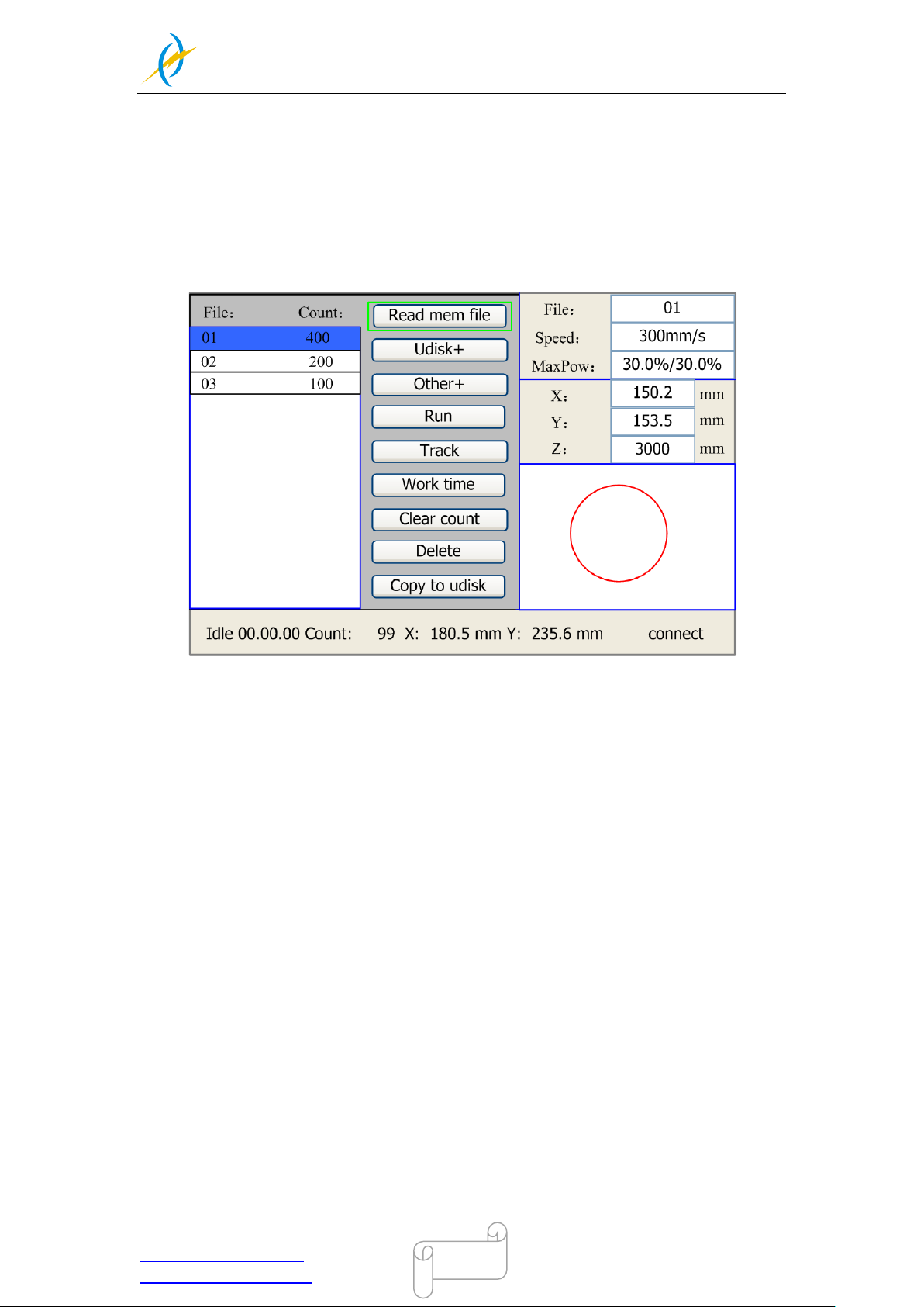
1). Memory File
On the main interface, if “File” button is pressed, it will show as below:
When showing this menu, the system would read the memory file firstly, the file name and
the work times would be listed in the area, and the selected file is previewed in the bottom
right area. “Y+/-” keys could be us ed to m ove the cur sor on the fi le nam e list. W hen the
cursor is on a target file name, presses the “Enter” key, the selected file will be previewed
on the main interface, and then if “Esc” key is pushed, the preview will disappear.
“X+/-” keys could be used to move the cursor left and right. All the item show as below:
Read mem file: read the memory file list;
Udisk: read the U disk file list;
Other: the other operation of the memory files;
Run: To run the selected file;
Track: T o track the selected file, and the track mode is optional;
Work time: To forecast the running time of the selected file, and the time is
accurate to 1ms;
Clear count: To clear the running times of the selected file;
Delete: To delete the selected file in the memory;
Copy to Udisk: To copy the selected file to Udisk;
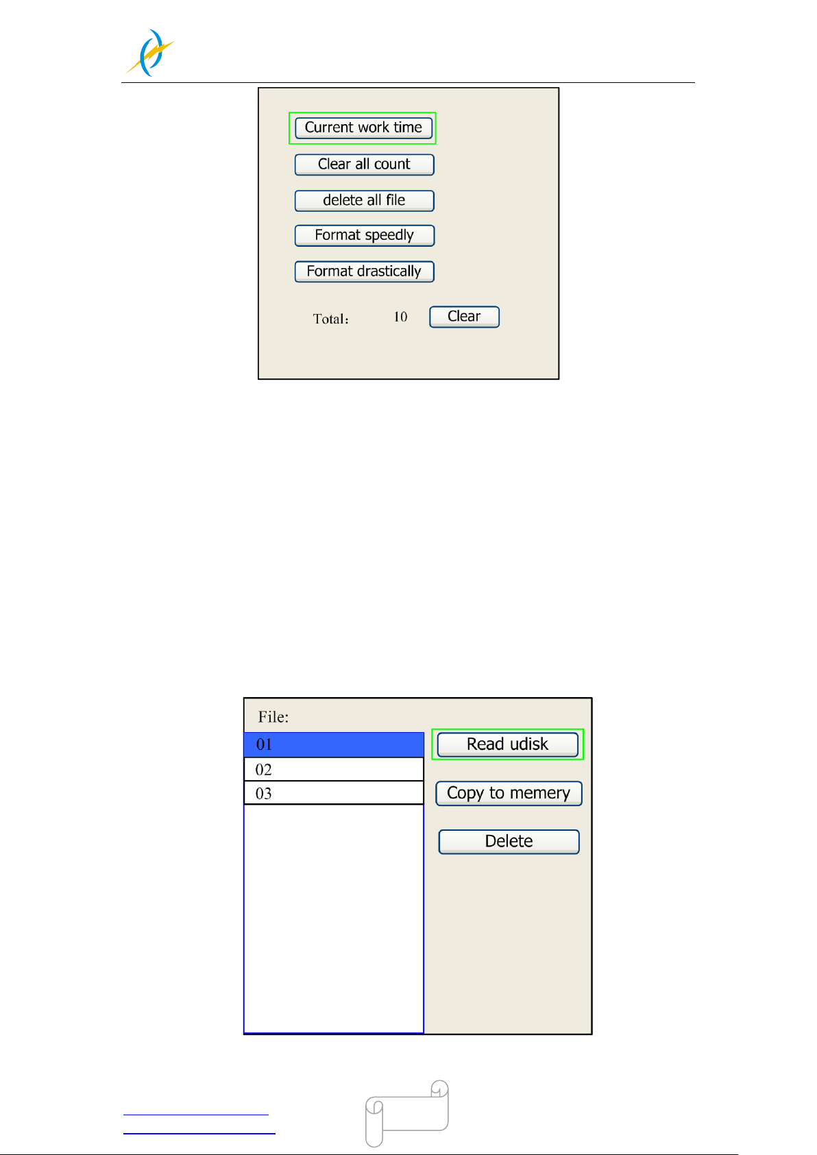
If the “Other” entry is pressed, the system will show as below:
Tel :(86)769 826653
Page 48
THUNDER LASER
NOVA-24
www.thunderlaser.com DONGGUAN THUNDER LASER EQUIPMENT CO.,LTD
[email protected] Shatian Town, Shatian Dadao, Mintian
Dongguan City, Guangdong Province, China
48
Current work time: To forecast the running time of the current file(the current
file No. is showed on the main interface), and the time is accurate to 1ms.
Clear all count: To clear the running times of every file in the memory
Delete all file: To delete all memory files
Format speedily: To format memory speedily, and then all the files in memory
will be deleted.
Format drastically: To format memory drastically, and then all the files in
memory will be deleted.
Total: the total running times of all the files.
2). U-Disk File
If the “U-disk+” entry is pr ess ed, you can cop y your fi l e from U SB fl ash dr i ve to your
machine.
Tel :(86)769 826653
Page 49
THUNDER LASER
NOVA-24
www.thunderlaser.com DONGGUAN THUNDER LASER EQUIPMENT CO.,LTD
[email protected] Shatian Town, Shatian Dadao, Mintian
Dongguan City, Guangdong Province, China
49
Read Udisk: read the file list in the Udisk;
Copy to memory: copy the target Udisk file to the memory;
Delete: delete the selected Udisk file;
The controller can only compatible with USB 2.0 and at most 16G USB
flash drive.
For USB flash drive,you can use the one came with the machine to
copy the file to your machine
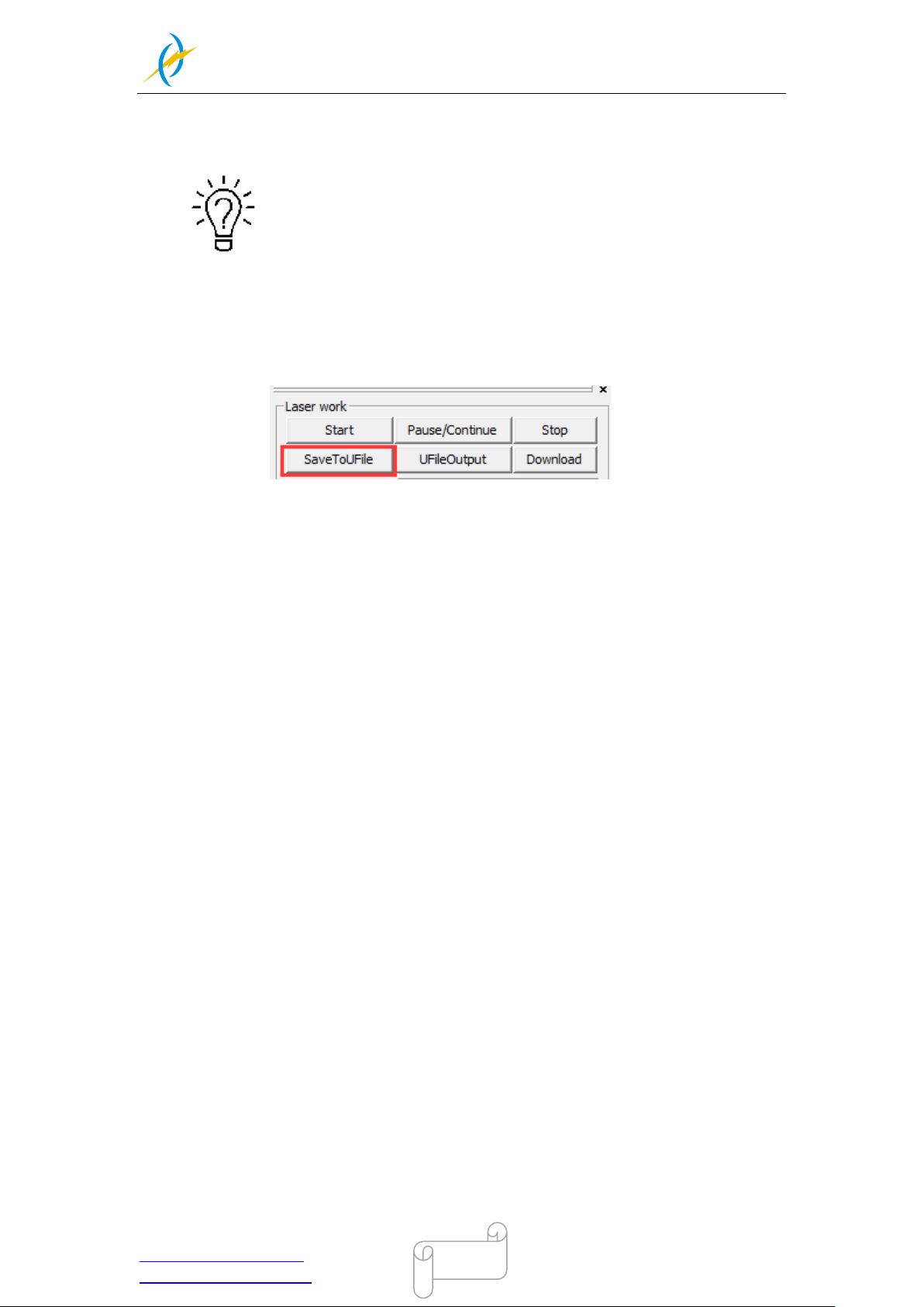
The file should be .rd file and it’s created by the “SaveToUFile” key on
the RDworks.
Tel :(86)769 826653
Page 50
THUNDER LASER
NOVA-24
www.thunderlaser.com DONGGUAN THUNDER LASER EQUIPMENT CO.,LTD
[email protected] Shatian Town, Shatian Dadao, Mintian
Dongguan City, Guangdong Province, China
50
4.5 How to use the different nozzles laser head co n e
The standard laser head is equipped with a 2 "(50.8mm) focusing lens and focuses the laser beam
to a diameter of about 0.14mm (when using a glass laser tube).
With this laser head, you can perform fine engraving work (such as letters with 1.5mm height)
and cut materials up to 10mm thickness with good quality (depending on the laser power of the
machine).
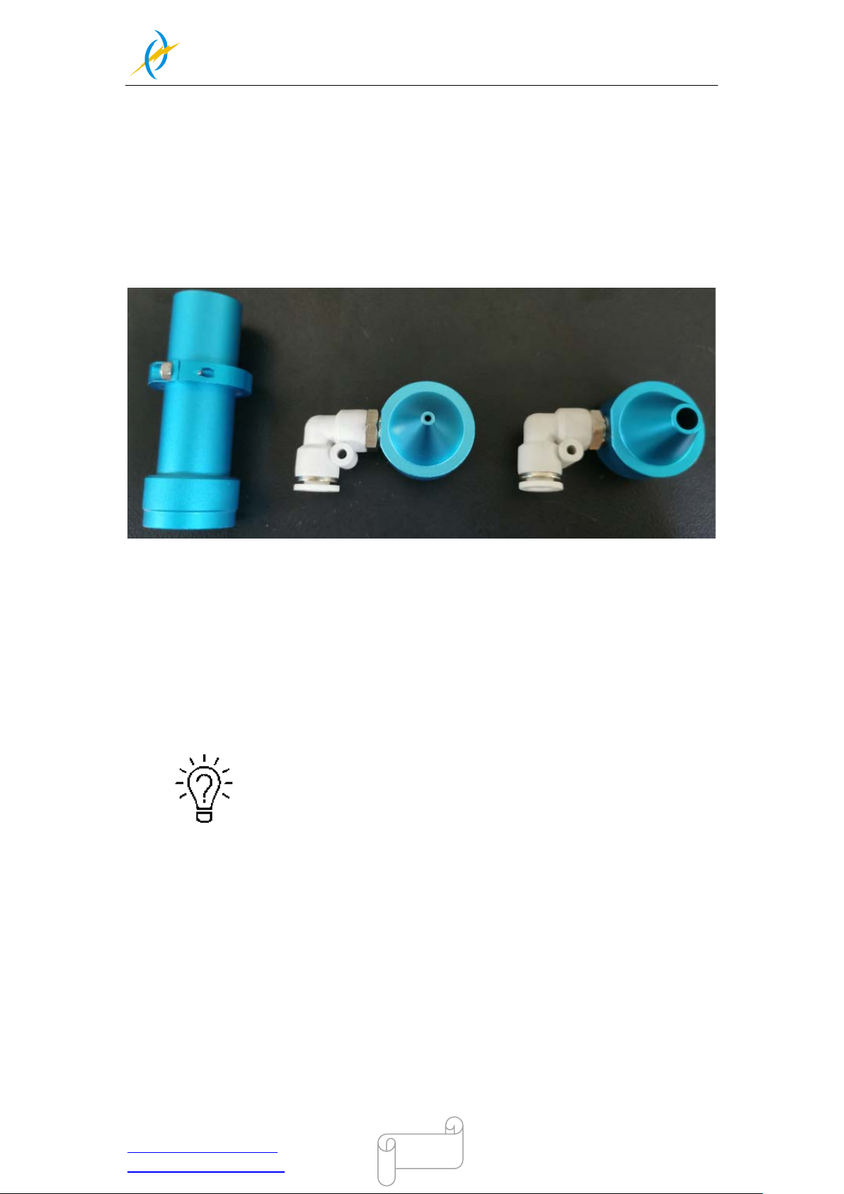
The standard laser head is supplied with 2 air nozzles laser head cone.
A nozzle has a very narrow outlet (approx. 2mm), which provides high air flow to blow directly on
the cutting gap. This nozzle is excellently suited for cutting wood, as this prevents soot formation
in the cutting gap.
The other nozzle has a large outlet (approx. 6 mm), which provides the air assist to blow the
material more slowly and not directly on the cutting gap. This nozzle is excellently suited for
cutting acrylic, as this prevents white mark in the cutting edge. Besides, when engraving wood,
for example, particles that have been removed and smoke / gases are gently distributed and
extracted in the working area. So you get a clean, almost unaffected by smoke traces engraving.
The 6mm nozzle laser head cone are placed inside the toolbox.
Tel :(86)769 826653
Page 51
THUNDER LASER
NOVA-24
www.thunderlaser.com DONGGUAN THUNDER LASER EQUIPMENT CO.,LTD
[email protected] Shatian Town, Shatian Dadao, Mintian
Dongguan City, Guangdong Province, China
51
4.6 How to replace the 4 inch and HR laser head
Both 4 inch laser head and HR laser head are option item.
The 4 inch laser head is suitable for cutting materials with a thickness> 10mm.
With this look, you can achieve vertical cuts in 20 or 30mm thick materials, such as PU foam,
acrylic or wood.
The High Resolution head can focus the laser beam much finer than the standard laser head.
This allows very delicate engraving or extremely precise cuts in films, cardboard or paper.
For cutting materials thicker than 1mm, the HR head is not suitable.
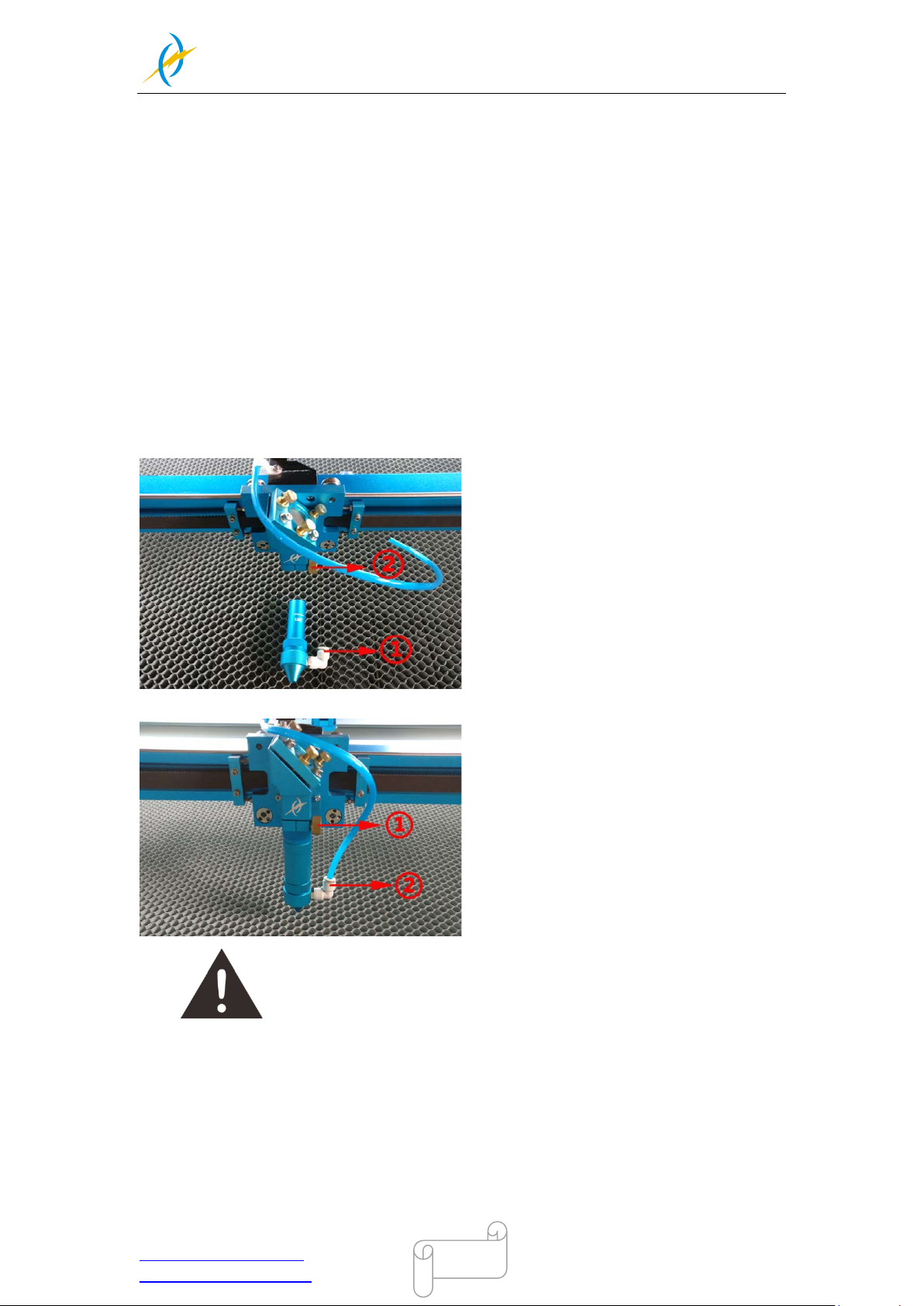
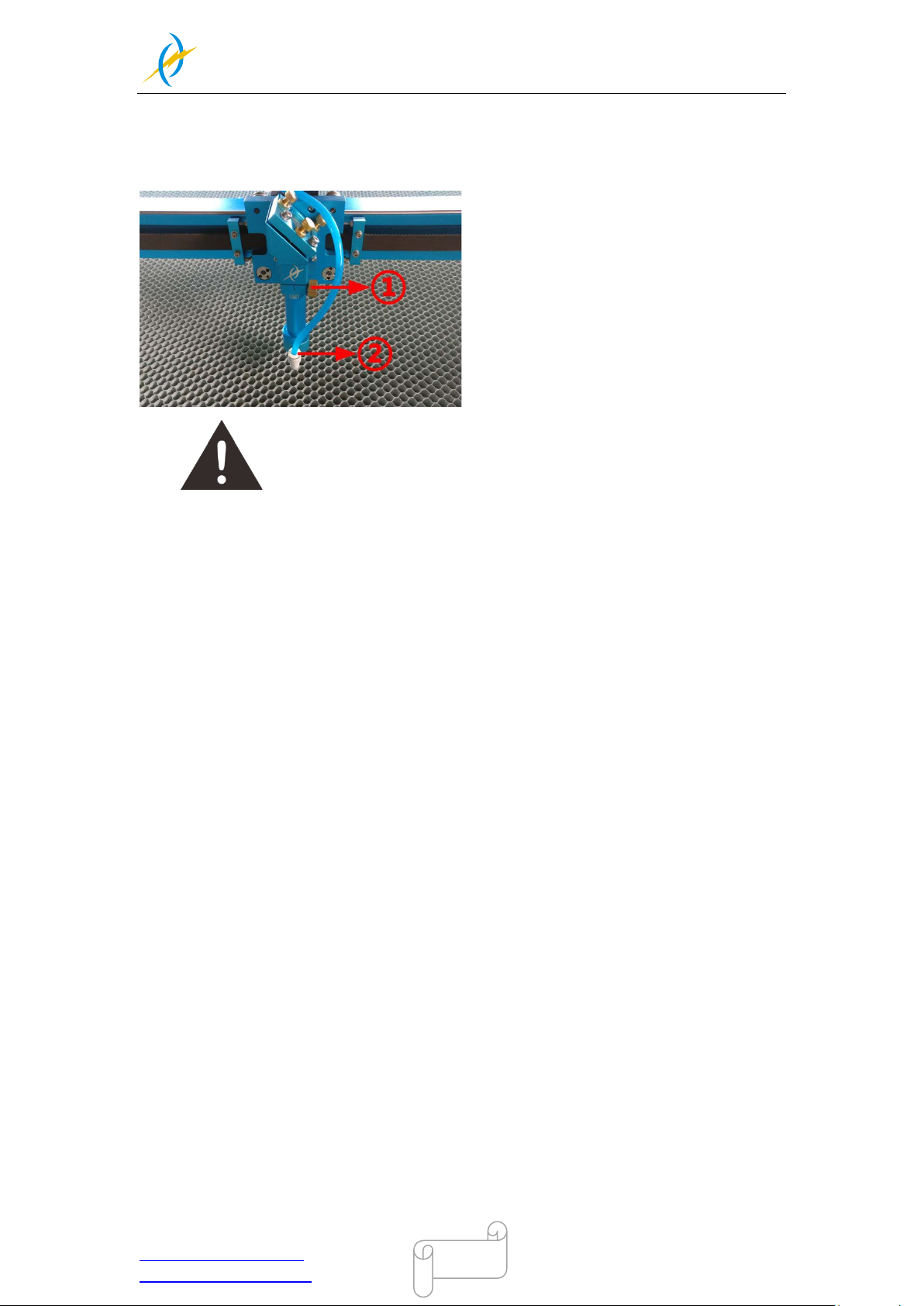
1)How to replace the 4 inch laser head
1. Move the table down till there’s enough space to take the standard head out and install
the 4” laser head.
2. Remove the standard head like below:
①
Take out the air hose
②
Loosen the screw
3. Install the 4” laser head like below:
①
Fix the laser head
②
Connect the air hose
Please always insert the 4’’ laser head as far as it will go.
Tel :(86)769 826653
Page 52
THUNDER LASER
NOVA-35
www.thunderlaser.com DONGGUAN THUNDER LASER EQUIPMENT CO.,LTD
[email protected] Shatian Town, Shatian Dadao, Mintian
Dongguan City, Guangdong Province, China
52
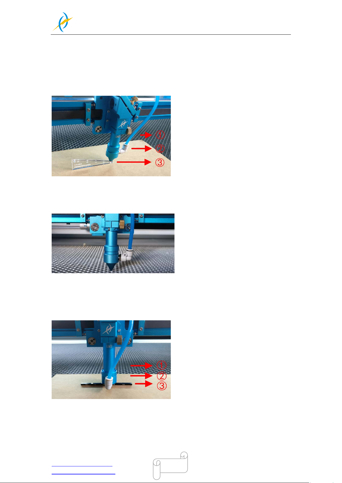
2)How to replace the HR laser head
1. Move the table down till there’s enough space to take the standard head out and install
the HR head.
2. Install HR head, like below:
Since HR head is sensitive for focus distance, it’s suggested to adjust
the focus by manual rather than auto focus.
①
Fix the laser head
②
Connect the air hose
Tel :(86)769 826653
Page 53
THUNDER LASER
NOVA-35
www.thunderlaser.com DONGGUAN THUNDER LASER EQUIPMENT CO.,LTD
[email protected] Shatian Town, Shatian Dadao, Mintian
Dongguan City, Guangdong Province, China
53
4.7 How to adjust focus distance by manual or auto
1) How to adjust focus distance by manual
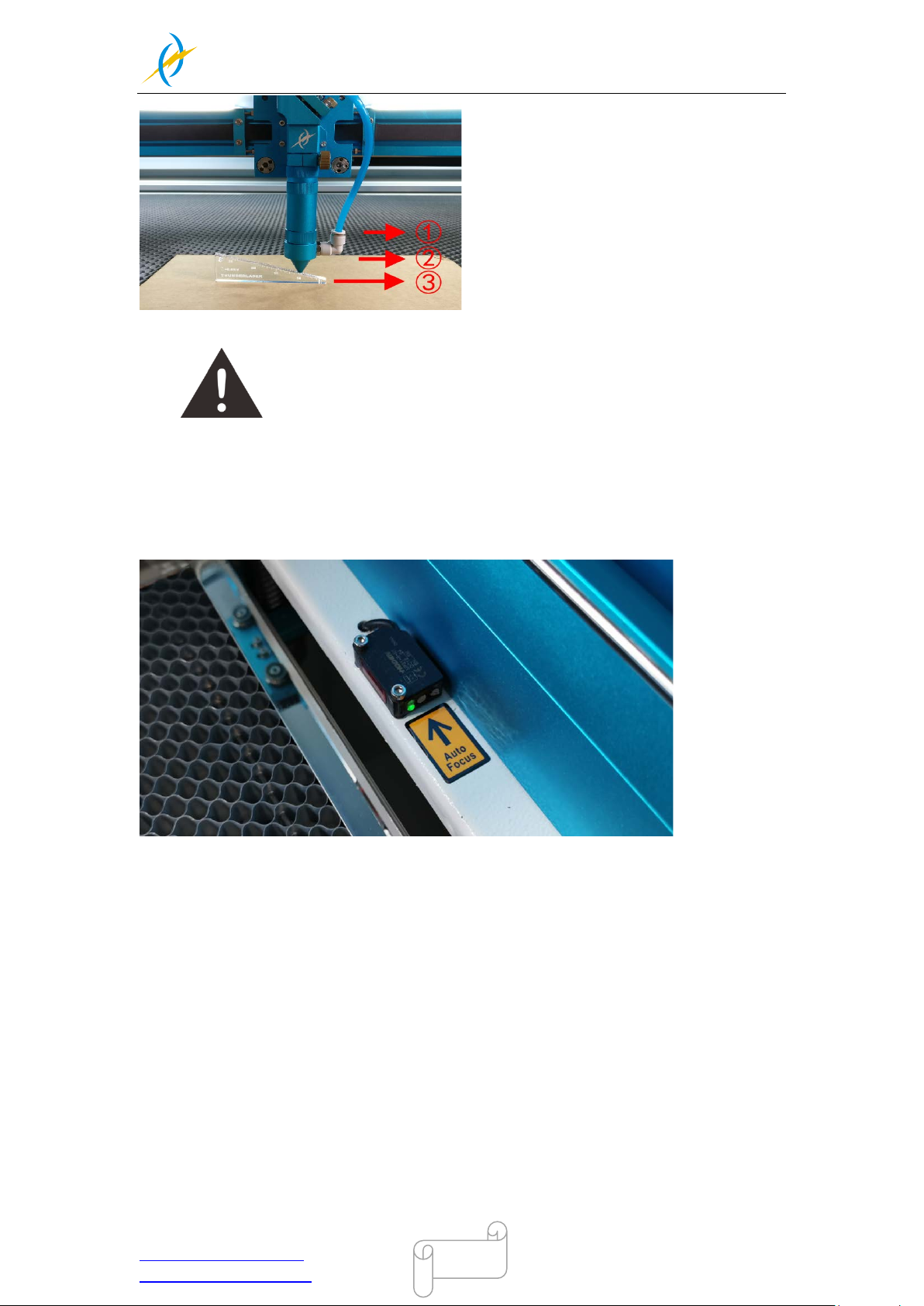
1. Standard laser head:
The focus distance between the standard laser head and the material is 6mm.
Find the 6mm thickness Acrylic Focus Ruler for help to adjust the focus directly like below:
①
Working Table
②
Material
③
Focus Ruler
Please not e th at t he l im i t l ine of the he ad, this l imi t l ine i ndi cates the m a x height of las er
head, and keep the limited l ine inside the l aser head mount. So as to protec t the laser
head from crashing into the honey comb table while z-axis does reset/auto focus
2. HR laser head
The focus distance between the HR laser head and the material is 3.5mm.
Since HR head is very sensitive for focus distance, thus we’ve tested and made a special
focus tool (with a best distance) for each HR head, like below:
①
Working Table
②
Material
③
Focus T ool
3. Four inch laser head
The focus distance between the 4” laser head and the material is 10mm.
4” laser head is not so sensitive for focus distance; you can set the distance about
10mm~12mm with the help of focus ruler, like below:
Tel :(86)769 826653
Page 54
THUNDER LASER
NOVA-35
www.thunderlaser.com DONGGUAN THUNDER LASER EQUIPMENT CO.,LTD
[email protected] Shatian Town, Shatian Dadao, Mintian
Dongguan City, Guangdong Province, China
54
Please always insert the 4’’ laser head as far as it will go.
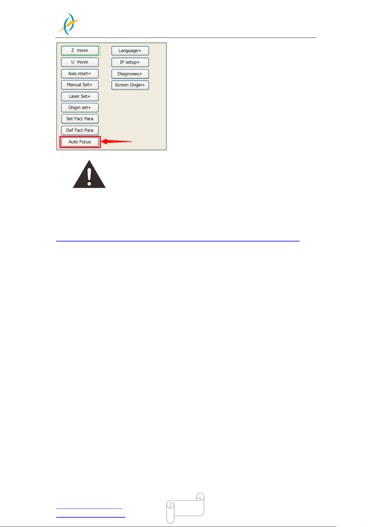
2) How to adjust focus distance by Auto
The Standard laser head will be provided with a stop ring. Always insert the laser head as
far as it will go, so that the correct focus distance is set during automatic focusing.
①
Working Table
②
Material
③
Focus Ruler
Move the tabl e down ti ll ther e’s enough spac e, t hen pl ac e the m ateri al betwee n the auto
focus sensors.
Make sure you always insert as far as the laser head stops by the ring.
After that, go into Z/U button>>Select Auto Focus.
Tel :(86)769 826653
Page 55
THUNDER LASER
NOVA-35
www.thunderlaser.com DONGGUAN THUNDER LASER EQUIPMENT CO.,LTD
[email protected] Shatian Town, Shatian Dadao, Mintian
Dongguan City, Guangdong Province, China
55
Do not use “auto focus” function while using HR laser head or 4’’ laser
head.
Do not use “auto focus” function while using the transparent material.
Also you can refer to the video instruction below:
http://www.thunderlaser.com/how-to-use-your-laser-machine/how-to-use-auto-focus.html
Tel :(86)769 826653
Page 56
THUNDER LASER
NOVA-35
www.thunderlaser.com DONGGUAN THUNDER LASER EQUIPMENT CO.,LTD
[email protected] Shatian Town, Shatian Dadao, Mintian
Dongguan City, Guangdong Province, China
56
4.8 How to use the TL-Timer
The TL-Timer is an additional tool for laser machines.
It will control laser machines periphery like air pump, exhaust fan, warning lights, heat
alarm detector, electrical locks and lot of other stuff automatically.
This will increase the ease of use of your laser machine.
Please note the different types of connection, which makes the TL-Timer able to work with
each kind of laser controller.
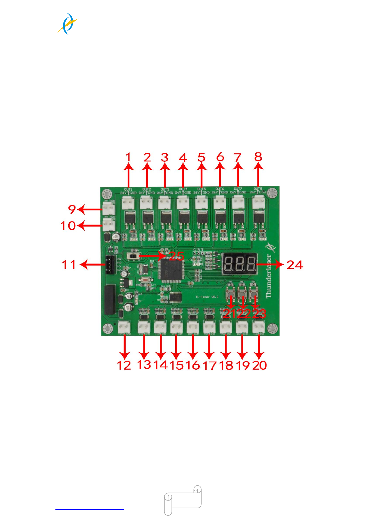
About TL-Timer controller interface and buttons description:
1. OUT1: Control the green light of warning light; When the machine is not at work, the
warning light is in green color;
2. OUT2: Control the red light of warning light; When the machine is working or getting
around alarm message on LCD panel, the warning light turns red;
3. OUT3: Control the exhaust fan; Delay shutdown is set to 15 second(Factory default
settings, change it if required);
4. OUT4: Control air assist with “Low volume”; Delay shutdown is set to 10 second
(Factory default settings, change it if required);
5. OUT5: Control air assist with “High volume”; Delay shutdown is set to 10 second
(Factory default settings, change it if required);
6. OUT6: Control the fire alarm system; When A high temp is detecting on working area,
Tel :(86)769 826653
Page 57

THUNDER LASER
NOVA-35
www.thunderlaser.com DONGGUAN THUNDER LASER EQUIPMENT CO.,LTD
[email protected] Shatian Town, Shatian Dadao, Mintian
Dongguan City, Guangdong Province, China
57
the alarm system will be active, the warning light alarms and the machine stops
working immediately;
7. OUT7: Control the power for rotary device;
8. OUT8: Spare interface;
9. 5V DC Voltage Power Output 1, control the power for red light pointer.
10. 5V DC Voltage Power Output 2, spare interface;
11. Upgrade interface;
12. 24V DC Voltage Power Input;
13. In1, “Working state” interface
14. In2, Reset interface;
15. In3, Air-assist mode selection;
16. In4, Control air assist with “Low volume”;
17. In5, Control air assist with “High volume”;
18. In6, Temperature detection
19. In7, Rotary connection state detection
20. In8, Spare interface
21. ”Set” button, select each ”OUT” interface and confirm the setting;
22. ”DOWN” button, reduce time of delay shutdown;
23. ”UP” button, increase time of delay shutdown
24. LED lights display, set the delay time for viewing each interface and enter
25. Auto and manual mode switch;
The TL-Timer is installed inside the lower right hand door panel, see below.
Normal use:
The TL-Timer is selected Auto mode as factory setting.
Under Auto mode, when the l aser i s not at work, ai r assist and exhaust fan won’t be on;
When the laser is wor king, the ai r assis t and e xhaust fan starts , after the job fini shed, the
air assist will stop after 10 second, exhaust fan will stop after 15 second.
Under Manual m ode, when the laser is power ed on, the air assi st and exhaust fan wi ll be
on all the time
Each “OUT” interface has a freely adjustable delay time from 0-99 seconds.
Set up delay time:
Generally, there’s only need to set up the delay time for air assist and exhaust fan, so they
can be dela y to shutdown acc ordi ng to your need. T he defaul t for air assist is 10 second,
and for exhaust fan is 15 second.
Click “Set” button to select from OUT1 to OUT 8 interfac e and the L ED light display will
show you the dela y time in sec ond for each interfac e. On each interfac e, click “down” or
“up” button you can change the value, then cl ick “Set” button to confirm and go into t he
next interface. O n the OUT8 i nterface, clic k again the “Set” button, the di splay wi ll be off
and exit the delay time setup.
Operation:
Tel :(86)769 826653
Page 58
THUNDER LASER
NOVA-35
www.thunderlaser.com DONGGUAN THUNDER LASER EQUIPMENT CO.,LTD
[email protected] Shatian Town, Shatian Dadao, Mintian
Dongguan City, Guangdong Province, China
58
4.9 How to use air-assist con tr ol
The Air-assist control is an additional tool for laser machines.
Generally, cutting needs the air as sist with high ai r-volume but engra ving needs the ai r
assist with low air-volume.
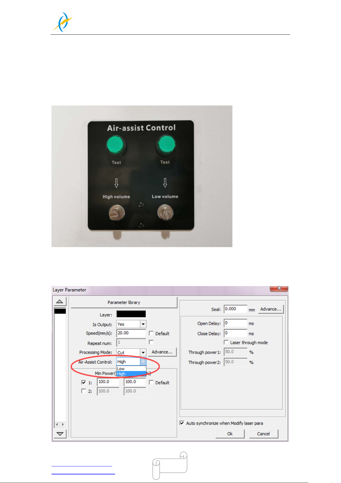
Air-assist control is availabl e in high- and l ow-volume for engraving and c utting-jobs via
software-setting, this will increase the ease of use of your laser machine.
1) How to select the air assist with high volume or low volume?
In R Dwork software, hi gh volume or low avolume is selected on the “Air Assist Control”
option. We s uggest s el ect “Hi gh” for cut mode and s el ect “Low” for scan m ode(engr a ving
mode).
Tel :(86)769 826653
Page 59
THUNDER LASER
NOVA-35
www.thunderlaser.com DONGGUAN THUNDER LASER EQUIPMENT CO.,LTD
[email protected] Shatian Town, Shatian Dadao, Mintian
Dongguan City, Guangdong Province, China
59
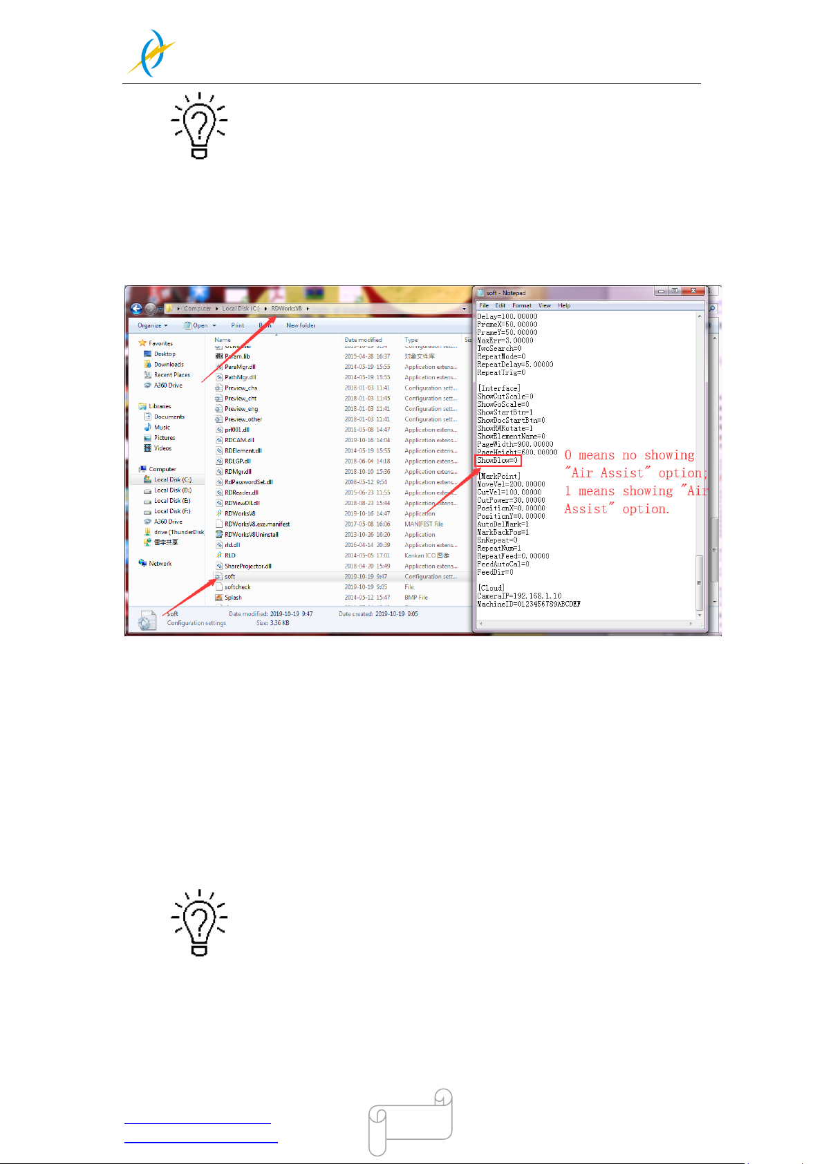
You can also set default for “Air-Assist Control” option, so in cut mode, it
will select High volume automatically, and in scan mode(engraving
mode),it will select Low volume automatically.
How to set defaul t for “Air-Assist Control” option?
Go into the RDw orks’s root di rector y>>open the te xt fil e of “soft”> >change the s etting of
“ShowBlow”>>save the text file, like below.
2) How to adjust a ir volume if r equire?
For High volume mode,
1. Make sure machine is not at work and laser switch is off
2. Click the left green button to start the air-assist with high volume
3. Check the air volume under the laser head
4. On left flow control valve, loose the locked nut then rotate the adjusting screw to
control the air volume to mean your requirements.
5. Fix the locked nut after finished.
And for Low volume mode, you do it the same.
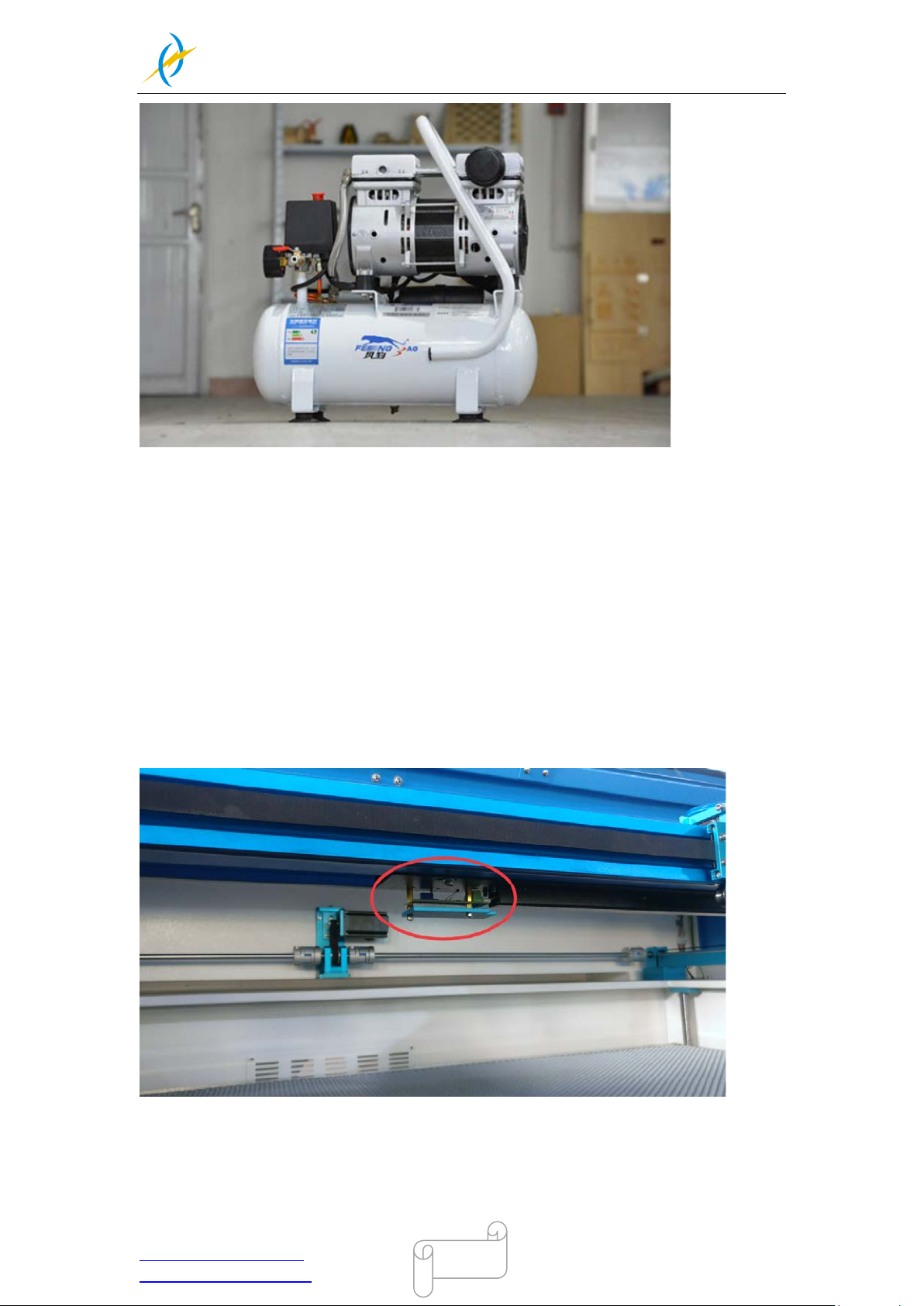
It will be the best if using big air compressor instead of air pump for
air-assist.
Tel :(86)769 826653
Page 60
THUNDER LASER
NOVA-35
www.thunderlaser.com DONGGUAN THUNDER LASER EQUIPMENT CO.,LTD
[email protected] Shatian Town, Shatian Dadao, Mintian
Dongguan City, Guangdong Province, China
60
4.10 How the heat alarm sy st e m works
The heat alarm system is an additional tool for laser machines.
Some mater i als suc h as acr ylic, w ood and so on, c an easi l y catch fir e, parti c ularl y during
cutting, the heat alarm system have a temperature sensor board which will react the
abnormal temperature(higher than 55°C/131°F) on m aterial processing chamber. It will
trigger at a c ertain temperature to stop laser processing and give a warning s ound, so
operator can active fire control in time to reduce the potential losses and risks.
Tel :(86)769 826653
Page 61
THUNDER LASER
NOVA-35
www.thunderlaser.com DONGGUAN THUNDER LASER EQUIPMENT CO.,LTD
[email protected] Shatian Town, Shatian Dadao, Mintian
Dongguan City, Guangdong Province, China
61
4.11 The First Time Running the Laser
To be safe, never ever run the laser system unattended.
According to international standard,“ O”means close;“ I”means open
for the rocker switch below
Yours first engraving tests
The following steps describe how to successfully engrave a first pattern. Please follow the
individual steps:
1. First switch on the water chiller.
2. Switch on you Laser and wait for a beep to note the machine is initialized, and the laser
head will do the reset and find the home from top left corner.DO NOT click “ESC” button to
stop the system initialization.
When turn on the power of machine, and note that turn on the Main
switch first and then the Laser switch.
3. Aft er machine finish res etting, adjust the hei ght of working tabl e, place the m aterial
usually on the top left corner of the working table.
① Click Z/U button;
② Select “Z move”;
③ Left arrow to move down;
④ Place the material;
⑤ Right arrow to move up;
4. With the help of the focus ruler, adjust the focus distance to 6mm between the bottom of
laser head and the material manually by move up and down the working table.
Open the software RDworksV8.First to set up the values on the “Scanning(Reverse
compernation)” check box.
5. Open Config(s)>>system setting>>Optimize>>Scanning(Reverse compensation),and
there are some default values on the “Scanning(Reverse compernation)” check box.
Tel :(86)769 826653
Page 62
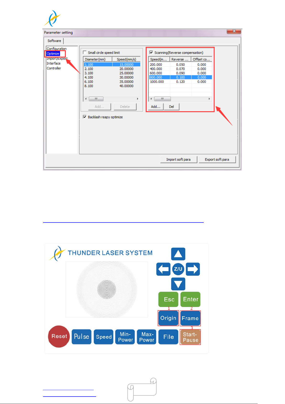
THUNDER LASER
NOVA-35
www.thunderlaser.com DONGGUAN THUNDER LASER EQUIPMENT CO.,LTD
[email protected] Shatian Town, Shatian Dadao, Mintian
Dongguan City, Guangdong Province, China
62
The particular values are showing with a picture in the USB flash drive and on the
Anodized aluminum piece that came with your machine.
Save those setting on the “Scanning(Reverse compernation)” check box.
6. Create sample text for engraving directly on RDworks, then set up the parameter and
download the file to your machine.
More details for how to use software please watch the instruction video below.
https://www.thunderlaser.com/video/how-to-use-your-laser-software.html
7. Click “Original” and “Frame” on the display, please make sure that the material is in the
right location and there is enough space for working.
① Control arrow button to move the laser head;
② Click “Origin” button to select the start point;
Tel :(86)769 826653
Page 63

THUNDER LASER
NOVA-35
www.thunderlaser.com DONGGUAN THUNDER LASER EQUIPMENT CO.,LTD
[email protected] Shatian Town, Shatian Dadao, Mintian
Dongguan City, Guangdong Province, China
63
③ Click “Frame” button to be sure the working area;
④ Click “Start-Pause” to run the program;
8. Please check the water cooling system is working properly; the water is running into
and filling the laser tube. Please do not start your work if the laser tube isn’t full of water,
because that may led to laser tube damage due to the high temper ature.
9. Finally press the “Start-Pause” button in the display, to start the engraving process.
10. While the laser is engraving, you can generate the next graphic.
11. When the engraving is complete, the laser machine will give out the notification sound
and the laser head will go back to the original point, and the warning light will return to the
green light, then you can repeat engraving.
Tel :(86)769 826653
Page 64
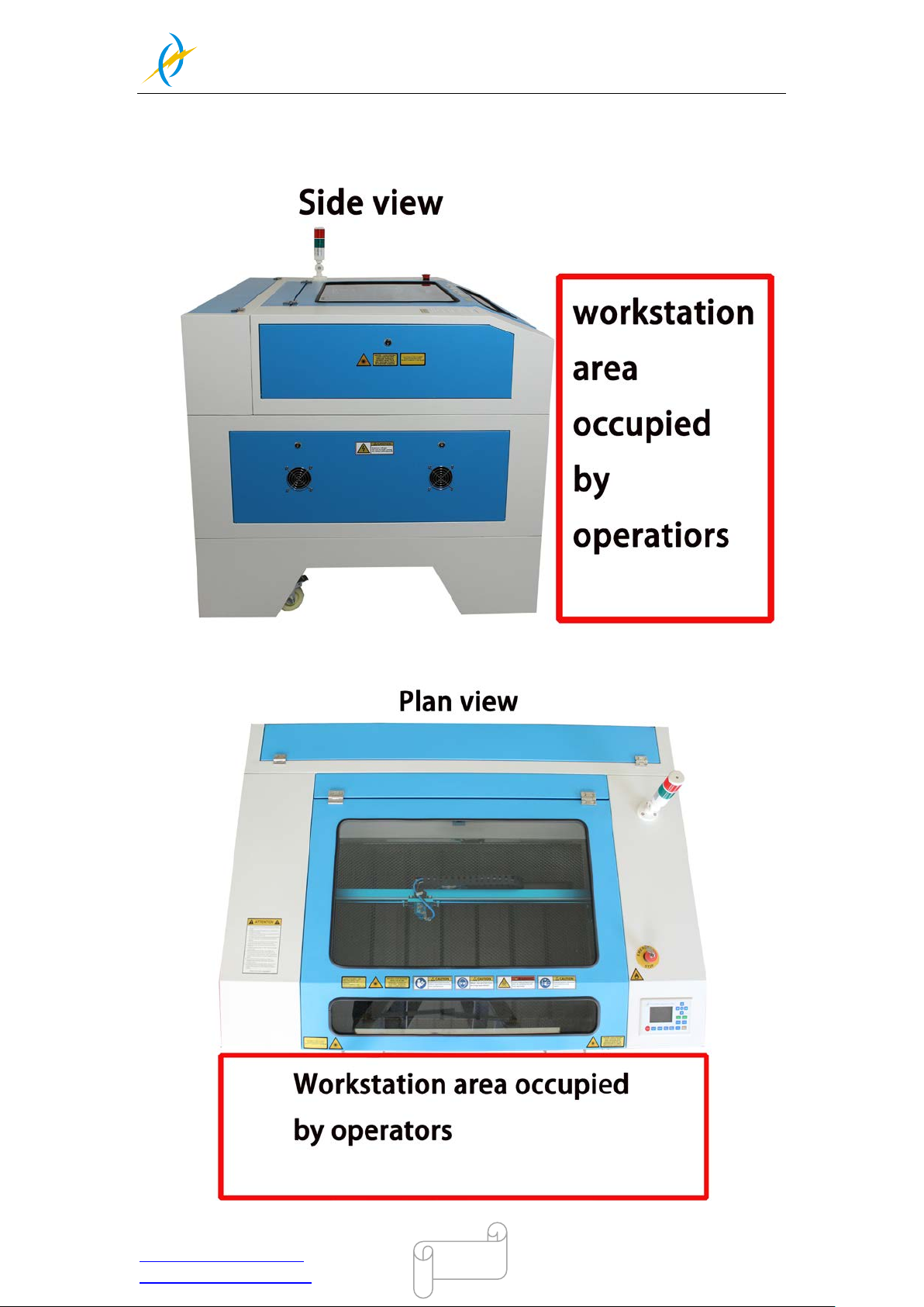
THUNDER LASER
NOVA-35
www.thunderlaser.com DONGGUAN THUNDER LASER EQUIPMENT CO.,LTD
[email protected] Shatian Town, Shatian Dadao, Mintian
Dongguan City, Guangdong Province, China
64
4.12 Workstation Area Indication
Tel :(86)769 826653
Page 65
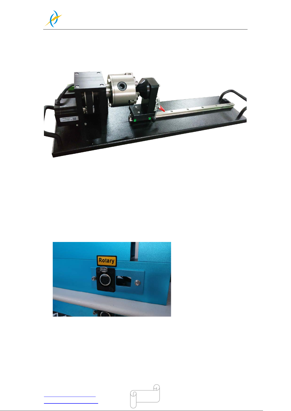
THUNDER LASER
NOVA-35
www.thunderlaser.com DONGGUAN THUNDER LASER EQUIPMENT CO.,LTD
[email protected] Shatian Town, Shatian Dadao, Mintian
Dongguan City, Guangdong Province, China
65
4.13 How to use the Rotary axis Attachment
To install and set-up the rotary axis attachment proceed as described as follows:
1. Move the working table to the lower position then switch off the laser and open the top
lid.
2. Put the rotar y axis attachm ent onto th e wor king t abl e and ali gn the r otar y attachm ent
with the x-axis are paral l el, w ith the j aw c huc k closes t to where the rotary attac hm ent
plugs in.
3. Connect the rotar y axis attachment via the control cabl e with the connec tor of the
motion s ystem. T he connec tor i s loc ated i nside the right fr ont of the laser. Connected
it to this interfac e and fixed, and the n you have fini shed the de vice con nection. Like
below:
4. Before you mount the objec t i nto the rotar y axis attachm ent, m eas ure the di ameter of
the object at the pos ition to be engr aved with a sl iding cali per or a similar tool. Wri te
down this value. For example: 80mm.
5. Adjust and fix the slider to make the work piece fitting into the rotary axis attachment.
6. Set your focus manuall y, c arefully and s afely. It is not recomm ended to use the auto
focus with a rotary axis attachment for the simple reason that you are not working with
a flat object. Set your origin
Tel :(86)769 826653
Page 66

THUNDER LASER
NOVA-35
www.thunderlaser.com DONGGUAN THUNDER LASER EQUIPMENT CO.,LTD
[email protected] Shatian Town, Shatian Dadao, Mintian
Dongguan City, Guangdong Province, China
66
7. Generate a graphi c w ith the hel p of the gr aphics software. T he gr aphics size must be
adjusted until less than the dimensions of the work piece.
8. Select “Output”, and then input the diameter of the object and the circle pulse. How to
set up the parameter for “enable rotate engrave”, please click below link for the
instruction
https://www.thunderlaser.com/uncategorized/rotary-axis-attachment-has-a-wrong-cylindrical-en
graving-cutting-size.html
9. Selec t "Download", click “Origin” and “Frame” on the LCD display, pl ease m ake sure
that the material is in the right location and enough space for working.
10. Finally press the “Start-Pause” button in the LCD display, to start the engraving or
cutting process.
Also you can refer to the video of how the rotary axis works in our website:
https://www.thunderlaser.com/how-to-use-your-laser-machine/how-the-rotary-axis-works.html
Tel :(86)769 826653
Page 67

THUNDER LASER
NOVA-35
www.thunderlaser.com DONGGUAN THUNDER LASER EQUIPMENT CO.,LTD
[email protected] Shatian Town, Shatian Dadao, Mintian
Dongguan City, Guangdong Province, China
67
4.14 For Laser Engr av ing
The engraving depth can easily be varied through the laser power or the speed. To
increas e the engra ving depth, reduce the s peed or inc rease the power s etting. T his way
you inc reas e the am ount o f en erg y per ar ea uni t. Engraving too de ep, howe v er, reduces
the qualit y of the details . With coated materi als the required power depends of the kind
and thickness of the coating. With power set too high the individual lines become too thick
and a sharp pic ture c annot be ac hieved. T he r es olution of the graphics should usually be
at 500 dpi. T he dpi setting (num ber of laser dots per inch) depends on the m aterial. T he
lower this setting is, the lower the resolution of the engraved picture will be. This, however,
reduces flaming and increases the energy of a pulse, which can improve the overall result
(e.g. when engraving some sorts of plastic materials).
1. Plastics
Plastics for engraving are available in many different colors and thicknesses and with
many different coatings and surfaces. The majority of available plastics can be well
engraved an d cut with the l aser. Plasti cs with a m icro-porous s urface seem to gi ve the
best result, because less surface material needs to be removed. As most plastic materials
have a low melting poi nt, a low pi p setting s hould be sel ected to reduce the danger of
melting.
2. Acrylic
There are two different types of acr yli c – c ast and extr uded. The cast acrylic becomes
white or m at a fter e ngra ving, the extr ude d acrylic r em ains c lear. Use e xtruded acrylic for
engravings that are fill ed with paint and cast ac rylic for norm al engravings. Cas t acrylic
can be best engraved without protection foil. It is better to engrave the entire surface with
a low energy setting.
3. Engrave the rubber stamp
The various m ixtures and densi ties of rubber plates cause a slightly varying engra ving
depth. The settings in the overview table give a good indication. Since engraving a
standard rubber material requires a relatively high laser power, the laser power is
principally set to 40% or more high and only the speed is varied. Due to their lower density,
so-called micro porous rubber materials allow a significantly higher engraving speed. Test
the rubber first, to find out the correct speed setting.
The RDWorksV8 software using the engraving function, you can choose “Ramp Effect” or
common engr a ving, onc e you c hoose “ Ram p E ffect” a nd you wi ll need to s et a m inim um
power lower than Max Power, generally we set it to about 15%, and input a value with the
Ramp Length what you want, but if you want to make it better, you may need to test
different kinds of power and speed by yourself, then you can get the best result.
Engra ving r ubb er pr oduces a c onsi derabl e am ount of d us t and terribl e gas . Ther efore a
well-dimensioned exhaust system and its regular maintenance are very important.
Tel :(86)769 826653
Page 68
THUNDER LASER
NOVA-35
www.thunderlaser.com DONGGUAN THUNDER LASER EQUIPMENT CO.,LTD
[email protected] Shatian Town, Shatian Dadao, Mintian
Dongguan City, Guangdong Province, China
68
Chapter5 Maintenance
5.1 Clea nin g the Laser Machine
Caution – use of controls or adjustments or performance of procedures other than
those specified here in may result in hazardous laser radiation exposure.
Before starting cleaning and maintenance work always switch off the device and
unplug the mains plug.
Always keep the system clean, as flammable parts in the working area or exhaust
area rise the fire hazard.
You should check at least once a day, whether dust has accumulated in the
engraving system. In case of soiling the machine must be cleaned. The cleaning
interval strongly depends on the material that is being processed and the operating
time of the device. Please bear in mind that only a clean machine guarantees
optimal performance and reduces the service costs.
General Cleaning Notes:
1. Make sure, that the device is switched off and unplugged. Open the protective cover.
2. Move the working table into a position in which it is easiest for you to clean the surface
with a window cleaning agent and paper towels.
3. Thoroughly remove all loose dirt particles and deposits in the interior of the machine.
4. Clean the cover of the laser tube.
5. You can clean the viewing window with a cotton cloth. Do not use paper towels as they
could scratch the acrylic.
Tel :(86)769 826653
Page 69
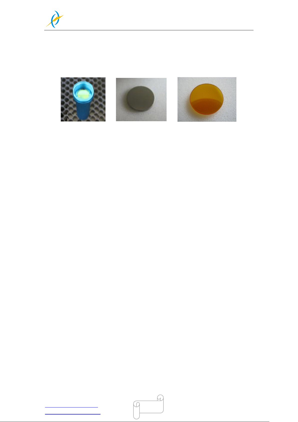
THUNDER LASER
NOVA-35
www.thunderlaser.com DONGGUAN THUNDER LASER EQUIPMENT CO.,LTD
[email protected] Shatian Town, Shatian Dadao, Mintian
Dongguan City, Guangdong Province, China
69
5.2 Cleaning the Optical Parts
The lens has a durable multi-coating and won’t be damaged by correct and careful
cleaning. You should inspect the focus lens and the mirrors and the beam combiner
according the maintenance plan. If you discover a veil of haze or dirt, you must clean them.
It is suggested to clean the mirrors/lens before work every day in order to run the machine
at max efficiency.
Follow the instructions below for the cleaning of optical parts:
5.2.1 Cleaning the Focus Lens
1. Move the engraving table to a distance approx. 10 cm under the lens holder.
2. Move the wor king head into the center of the w orking s urface and put a c loth under
the lens holder (so that the lens is not damaged if it accidentally falls out of its holder).
3. Now you can unscrew the lens holder.
4. Once positioned over a clean lens cleaning tissue, remove the lens from the lens
holder by carefully turning the lens holder and letting the lens and the O-ring drop onto
the cleaning cloth.
5. Examine the O-ring and, if nec essar y, clean i t with a cotton bud and a lens cleani ng
tissue/cloth.
6. Remove the coarse dust as good as possible by blowing air onto the lens surface.
7. Check the surfac e and if necessar y clean the lens wi th the lens cleani ng liquid and
lens tissue.
8. Hold the lens assem bl y by its edge with a lens cl eaning tis sue and us e a drop of lens
cleaning liquid from the little bottle which you received as an accessory delivered with
the laser. While holdi ng the l ens on an angl e, fl ush both s urfac es of the lens , to wash
away coarse soiling.
9. Put the lens on a clean lens cleaning tissue. Put some lens cleaning liquid on one side
of the lens. Leave the liquid to take effect for approximatel y one minute and then
gently wipe it away with lens cleaning tissues soaked with lens cleaning liquid.
10. Finall y, dry this side of the l ens wi th dry lens cleani ng ti ssues and r epeat the c leaning
process on the other side of the lens. Never use a cleaning tissue twice. Dust
accumulated in the cleaning tissue could scratch the lens surface.
11. Examine the lens. If it is still soiled, repeat the cleaning process until the lens is clean.
12. Carefully insert the lens into the lens holder. Ensure, that the rounded side (= convex)
of the lens is facing upwards. Then put the O-ring on top of the lens.
13. Carefully assemble the lens in reverse order.
Tel :(86)769 826653
Page 70
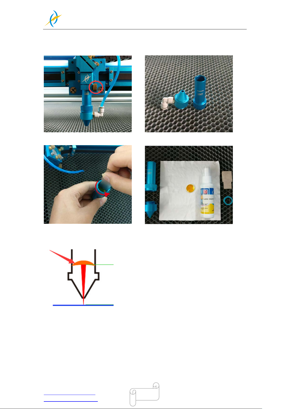
THUNDER LASER
NOVA-35
www.thunderlaser.com DONGGUAN THUNDER LASER EQUIPMENT CO.,LTD
[email protected] Shatian Town, Shatian Dadao, Mintian
Dongguan City, Guangdong Province, China
70
How to take out the focus lens, please just as following the picture i ndicated:
1. Remove the laser head 2. Divide the laser head
3. Remove the focus lens with the tool 4. Clean the lens with lens cloth
Note: The direction of focus lens mounting please refer to below picture:
Tel :(86)769 826653
Page 71
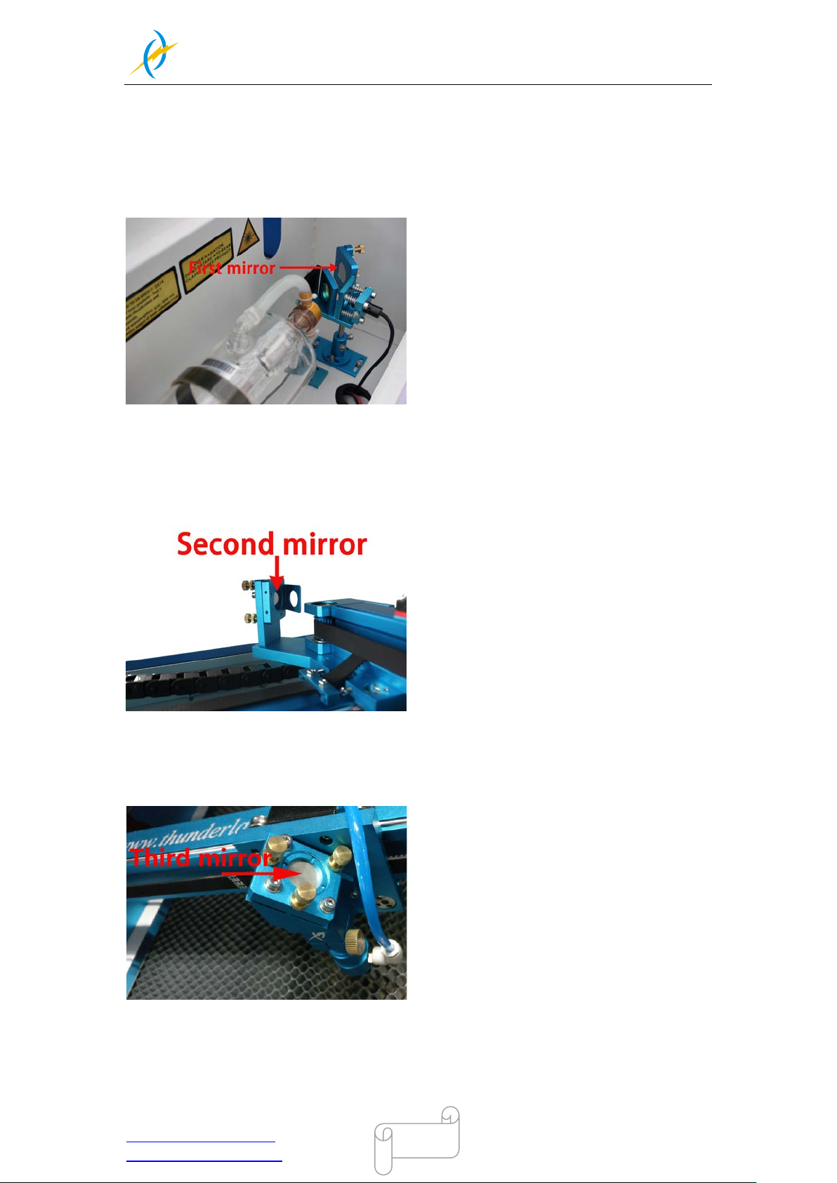
THUNDER LASER
NOVA-35
www.thunderlaser.com DONGGUAN THUNDER LASER EQUIPMENT CO.,LTD
[email protected] Shatian Town, Shatian Dadao, Mintian
Dongguan City, Guangdong Province, China
71
5.2.2 Cleaning the Mirrors
There are three mirrors in the operating area of the laser, which may have to be cleaned if
they are soiled. To clean the reflector, follow the instructions below.
The Mirror#1
The mirrors are easily get dirty. And this will reduce the efficiency of the laser beam.
Meanwhile, laser energy absorbed by the mirror may cause heat and destroy the mirrors
too. For the first mirror, you can clean them directly.
The Mirror#2
Make sure the p ower of t he laser mac hine is turned off while cl eaning. T he 2
installed on the left side of X rail. For the second mirror, you can clean them directly.
The Mirror#3
Cautions:
1) Mirrors m ust be cleaned carefull y b y using lens cleaning paper/lens cl eaning cloth to
avoid scratching the surface.
2) Do not touch the surface of the mirrors/lens after cleaning
nd
mirror is
Tel :(86)769 826653
Page 72
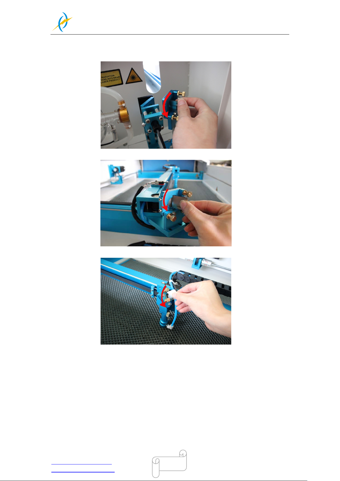
THUNDER LASER
NOVA-35
www.thunderlaser.com DONGGUAN THUNDER LASER EQUIPMENT CO.,LTD
[email protected] Shatian Town, Shatian Dadao, Mintian
Dongguan City, Guangdong Province, China
72
3) The concave side of the lens must be on the bottom when installed
How to take out the mirror#1 #2 and#3, and please just as following the pi cture
indicated:
1. The mirror#1
2. The mirror#2
3. The mirror#3
Tel :(86)769 826653
Page 73
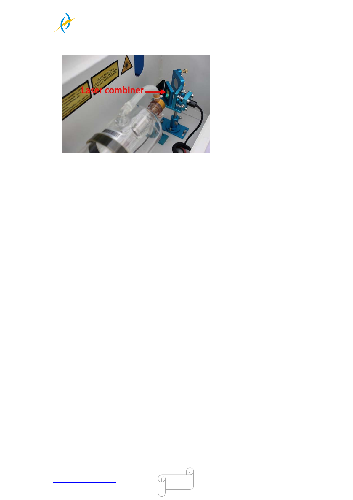
THUNDER LASER
NOVA-35
www.thunderlaser.com DONGGUAN THUNDER LASER EQUIPMENT CO.,LTD
[email protected] Shatian Town, Shatian Dadao, Mintian
Dongguan City, Guangdong Province, China
73
5.2.3 Cleaning Laser Combiner
① The beam combiner must be cleaned carefully by using lens cleaning paper/lens
cleaning cloth to avoid scratching the surface.
② Do not touch the surface of the beam combiner after cleaning.
③ For the beam combiner, you can clean them directly.
Tel :(86)769 826653
Page 74
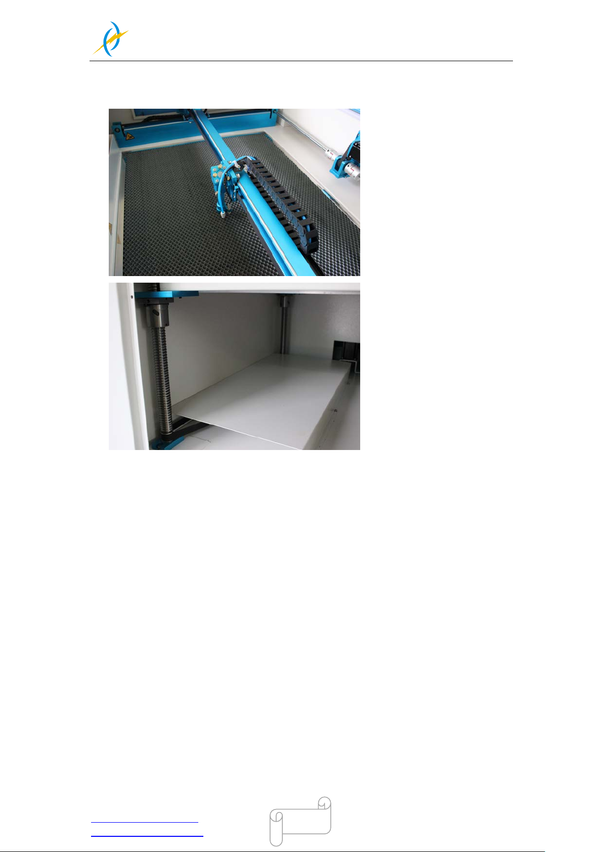
THUNDER LASER
NOVA-35
www.thunderlaser.com DONGGUAN THUNDER LASER EQUIPMENT CO.,LTD
[email protected] Shatian Town, Shatian Dadao, Mintian
Dongguan City, Guangdong Province, China
74
5.3 Maintain the X/Y/Z Rails
It is suggested to add lubricant oil (or Rust Preventati ve Grease) to the rails/screws at
least every two weeks.
Tel :(86)769 826653
Page 75
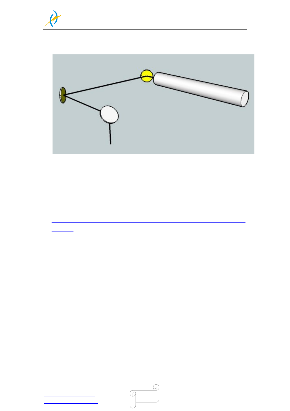
THUNDER LASER
NOVA-35
www.thunderlaser.com DONGGUAN THUNDER LASER EQUIPMENT CO.,LTD
[email protected] Shatian Town, Shatian Dadao, Mintian
Dongguan City, Guangdong Province, China
75
5.4 Check the Beam Path
After being used for a long tim e, the beam path m ight be defl ecti ve. This will reduc e
the efficient of the l aser beam or e ven cause no las er beam . At thi s m oment, you wil l
need to re-adjust the beam path again.
If you need to know that about adjust the laser beam path of the video on YouTube
released by our company and please link to the URL:
http://www.thunderlaser.com/how-to-use-your-laser-machine/how-to-adjust-the-laser-beam
-path.html
Tel :(86)769 826653
Page 76
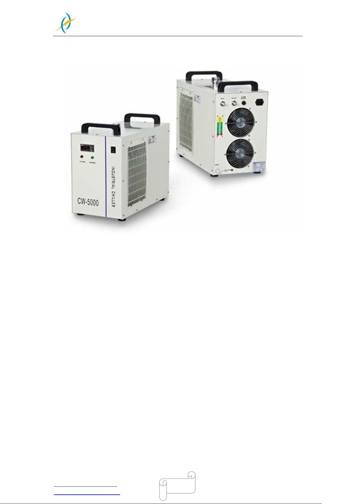
THUNDER LASER
NOVA-35
www.thunderlaser.com DONGGUAN THUNDER LASER EQUIPMENT CO.,LTD
[email protected] Shatian Town, Shatian Dadao, Mintian
Dongguan City, Guangdong Province, China
76
5.5 Change Cooling Water for The Water Chiller
It is suggested to change the water at least once every month
Make sure the l as er tube i s fi l l ed with w ater befor e star ti ng the m achi ne. It is ad vised
to add water every 3 days.
The quality and temperature of the cooling water affects the life time of the laser tube.
You need to use pure(distilled) water and control the temperature below 35℃(95℉).
Tel :(86)769 826653
Page 77

THUNDER LASER
NOVA-35
www.thunderlaser.com DONGGUAN THUNDER LASER EQUIPMENT CO.,LTD
[email protected] Shatian Town, Shatian Dadao, Mintian
Dongguan City, Guangdong Province, China
77
5.6 Maintenance Plan
DAILY CHECK LIST
1.
① Check Mirrors and lens for condensation and make sure it is clean after work
② Check exhaust grille to ensure there is no blockage for exhaust fan
③ Check coolant water level
④ Check air filter on compressor
⑤ Ensure cooling fans on sides are free from debris
⑥ The air blower must be checking and cleaning if required.
2. WEEKLY CHECK LIST
① Clean filters on water chiller
② Clean debris from under laser bed
③ Clean X & Y & Z axis rails and lubricate as required
④ Clean Acrylic/Tempered glass covers in lid
⑤ The beam combiner must be checking every weekly, and cleaning if required.
THE END
Tel :(86)769 826653
 Loading...