

Page 1
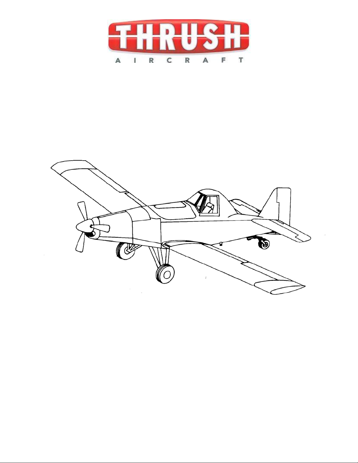
AIRCRAFT MAINTENANCE
MANUAL
SINGLE COCKPIT AND DUAL COCKP IT
Model S2R – G10
Serial Numbers S2R-G10 S/N G10-169 & up
Issued March 26, 2010
Note:
All serial numbers with the DC suffix indicate the dual cockpit configuration.
Manufacturer’s Serial Number: ____________
Registration Number: ________________ Thrush Aircraft
Inc.
P. O. Box 3149
300 Old Pretoria Road
Albany, GA 31706
Telephone: 229-883-1440
Fax: 229-436-4856
Effective: 03/26/2010
page
i
Page 2
THRUSH AIRCRAFT INC. – MODEL S2R-R1340
AIRCRAFT MAINTENANCE MANUAL
INTRODUCTION
This publication provides information for the Thrush Aircraft, Inc. Model S2R-G10 Turbo
Thrush airplane. Installations or equipment will vary from airplane to airplane due to the
wide range of optional equipment. The information contained within this manual is based
on data available at the time of publication and will be kept current by changes or service
publications.
This manual contains information on aircraft systems and operating procedures required for
safe and effective maintenance. It shall not be used as a substitute for sound judgment.
In this manual:
WARNING
INDICATES A STRONG POSSIBILITY OF SEVERE
PERSONAL INJURY OR LOSS OF LIFE IF
INSTRUCTIONS ARE NOT FOLLOWED.
CAUTION
Indicates a possibility of personal injury or
equipment damage if instructions are not followed.
* NOTE *
Gives helpful information.
Attention: Owners, Operators and Maintenance Personnel:
Detailed descriptions of standard workshop procedures, safety principles and service
operations are NOT included in this manual. Please note that this manual DOES contain
warnings and cautions against some specific service methods which could cause
PERSONAL INJURY or could damage an aircraft or MAKE IT UNSAFE. Please
understand that these warnings cannot cover all conceivable ways in which service,
whether or not recommended by Thrush Aircraft Inc., might be accomplished or of the
possible hazardous consequences of each conceivable method, nor could Thrush Aircraft
Inc. investigate all such ways. Anyone using service procedures or tools, whether or not
recommended by Thrush Aircraft Inc. must satisfy themselves thoroughly that neither
personal safety nor aircraft safety will be jeopardized.
All information contained in this manual is based on the latest product information available
at the time of printing. Thrush Aircraft, Inc. reserves the right to make changes at any time
without notice.
page Effective: 03/26/2010 ii
Page 3

THRUSH AIRCRAFT INC. – MODEL S2R-R1340
AIRCRAFT MAINTENANCE MANUAL
Manual Organization
This maintenance manual is divided into the following eleven sections, each with its own
table of contents:
SECTION 1..................................................GENERAL INFORMATION
SECTION 2..................................................SERVICING & INSPECTION
SECTION 3..................................................HYDRAULICS
SECTION 4.................................................. POWERPLANT AND PROPELLER
SECTION 5.................................................. FUEL SYSTEM
SECTION 6.................................................. LANDING GEAR, WHEELS & BRAKES
SECTION 7.................................................. FLIGHT CONTROLS
SECTION 8..................................................INSTRUMENTS
SECTION 9.................................................. DISPERSAL SYSTEMS
SECTION 10................................................ ELECTRICAL
SECTION 11................................................ AIRWORTHINESS LIMITATIONS
Effective: 03/26/2010
page iii
Page 4

THRUSH AIRCRAFT INC. – MODEL S2R-R1340
AIRCRAFT MAINTENANCE MANUAL
LOG OF PAGES
Page Date
i ...................................... 03/26/2010
ii ...................................... 03/26/2010
iii ...................................... 03/26/2010
iv ...................................... 03/26/2010
v ...................................... 03/26/2010
vi ...................................... 03/26/2010
vii ...................................... 03/26/2010
vii ...................................... 03/26/2010
viii BLANK 03/26/2010
INTRODUCTION
SECTION 1
GENERAL
INFORMATION
Page Date
1 ...................................... 03/26/2010
2 ...................................... 03/26/2010
3 ...................................... 03/26/2010
4 ...................................... 03/26/2010
5 ...................................... 03/26/2010
6 ...................................... 03/26/2010
7 ...................................... 03/26/2010
8 ...................................... 03/26/2010
SECTION 2
SERVICING &
INSPECTION
Page Date
1 ...................................... 03/26/2010
2 ...................................... 03/26/2010
3 ...................................... 03/26/2010
4 ...................................... 03/26/2010
5 ...................................... 03/26/2010
6 ...................................... 03/26/2010
7 ...................................... 03/26/2010
8 ...................................... 03/26/2010
9 ...................................... 03/26/2010
10 ...................................... 03/26/2010
11 ...................................... 03/26/2010
12 ...................................... 03/26/2010
13 ...................................... 03/26/2010
14 ...................................... 03/26/2010
15 ...................................... 03/26/2010
16 ...................................... 03/26/2010
17 ......................................
18 ...................................... 03/26/2010
19 ...................................... 03/26/2010
20 ...................................... 03/26/2010
21 ...................................... 03/26/2010
22 ...................................... 03/26/2010
23 ...................................... 03/26/2010
24 ...................................... 03/26/2010
25 ...................................... 03/26/2010
26 ...................................... 03/26/2010
03/26/2010
(Continued)
Page Date
27 ....................................... 03/26/2010
28 ....................................... 03/26/2010
29 ....................................... 03/26/2010
30 ....................................... 03/26/2010
31 ....................................... 03/26/2010
32 ....................................... 03/26/2010
33 ....................................... 03/26/2010
34 ....................................... 03/26/2010
35 ....................................... 03/26/2010
36 ....................................... 03/26/2010
37 ....................................... 03/26/2010
38 BLANK 03/26/2010
Page Date
1 ....................................... 03/26/2010
2 ....................................... 03/26/2010
3 ....................................... 03/26/2010
4 ....................................... 03/26/2010
5 ....................................... 03/26/2010
6 ....................................... 03/26/2010
SECTION 2
SERVICING &
INSPECTION
SECTION 3
HYDRAULICS
SECTION 4
POWERPLANT &
PROPELLER
Page Date
1 ....................................... 03/26/2010
2 ....................................... 03/26/2010
3 ....................................... 03/26/2010
4 ....................................... 03/26/2010
5 ....................................... 03/26/2010
6
7 ....................................... 03/26/2010
8 ....................................... 03/26/2010
9 ....................................... 03/26/2010
10 ....................................... 03/26/2010
11 ....................................... 03/26/2010
12 ....................................... 03/26/2010
13 ....................................... 03/26/2010
14 ....................................... 03/26/2010
15 ....................................... 03/26/2010
16 ....................................... 03/26/2010
17 ....................................... 03/26/2010
18 ....................................... 03/26/2010
Page Date
1 ....................................... 03/26/2010
2 ....................................... 03/26/2010
3 ....................................... 03/26/2010
4 ....................................... 03/26/2010
.......................................
SECTION 5
FUEL SYSTEM
03/26/2010
iv
page Effective: 03/26/2010
Page 5

THRUSH AIRCRAFT INC. – MODEL S2R-R1340
AIRCRAFT MAINTENANCE MANUAL
Page Date
5 ...................................... 03/26/2010
6 ...................................... 03/26/2010
7 ...................................... 03/26/2010
8 ...................................... 03/26/2010
9 ...................................... 03/26/2010
10 ...................................... 03/26/2010
11 ...................................... 03/26/2010
12 ...................................... 03/26/2010
13 ...................................... 03/26/2010
14 ...................................... 03/26/2010
15 ...................................... 03/26/2010
16 ...................................... 03/26/2010
17 ...................................... 03/26/2010
18 BLANK 03/26/2010
SECTION 5
FUEL SYSTEM
continued
SECTION 6
LANDING GEAR,
WHEELS &
BRAKES
Page Date
1 ...................................... 03/26/2010
2 ...................................... 03/26/2010
3 ...................................... 03/26/2010
4 ...................................... 03/26/2010
5 ...................................... 03/26/2010
6 ...................................... 03/26/2010
7 ...................................... 03/26/2010
8 ...................................... 03/26/2010
9 ...................................... 03/26/2010
10 ...................................... 03/26/2010
11 ...................................... 03/26/2010
12 ...................................... 03/26/2010
13 ...................................... 03/26/2010
14 ...................................... 03/26/2010
15 ...................................... 03/26/2010
16 ...................................... 03/26/2010
17 ...................................... 03/26/2010
18 ...................................... 03/26/2010
19 ...................................... 03/26/2010
20 BLANK 03/26/2010
SECTION 7
FLIGHT
CONTROLS
Page Date
1 ...................................... 03/26/2010
2 ...................................... 03/26/2010
3 ...................................... 03/26/2010
4 ...................................... 03/26/2010
5 ...................................... 03/26/2010
6 ...................................... 03/26/2010
7 ...................................... 03/26/2010
8 ...................................... 03/26/2010
Effective: 03/26/2010 page v
SECTION 7
FLIGHT
CONTROLS
Page Date
9 ...................................... 03/26/2010
10 ...................................... 03/26/2010
11 ...................................... 03/26/2010
12 ...................................... 03/26/2010
13 ...................................... 03/26/2010
14 ...................................... 03/26/2010
15 ...................................... 03/26/2010
16 ...................................... 03/26/2010
17 ...................................... 03/26/2010
18 ...................................... 03/26/2010
19 ...................................... 03/26/2010
20 ...................................... 03/26/2010
21 ...................................... 03/26/2010
22 ...................................... 03/26/2010
23 ...................................... 03/26/2010
24 ...................................... 03/26/2010
25 ...................................... 03/26/2010
26 ...................................... 03/26/2010
27 ...................................... 03/26/2010
28 ...................................... 03/26/2010
29 ...................................... 03/26/2010
30 ...................................... 03/26/2010
31 ...................................... 03/26/2010
32 BLANK 03/26/2010
Page Date
1 ...................................... 03/26/2010
2 ......................................
3 ...................................... 03/26/2010
4 ...................................... 03/26/2010
5 ...................................... 03/26/2010
6 ...................................... 03/26/2010
7 ...................................... 03/26/2010
8 ...................................... 03/26/2010
9 ...................................... 03/26/2010
10 ...................................... 03/26/2010
11 ...................................... 03/26/2010
12 ...................................... 03/26/2010
13 ...................................... 03/26/2010
14 ...................................... 03/26/2010
15 ...................................... 03/26/2010
16 ...................................... 03/26/2010
17 ...................................... 03/26/2010
18 BLANK 03/26/2010
continued
SECTION 8
INSTRUMENTS
03/26/2010
Page 6

THRUSH AIRCRAFT INC. – MODEL S2R-R1340
AIRCRAFT MAINTENANCE MANUAL
SECTION 9
DISPERSAL
SYSTEMS
Page Date
1 ...................................... 03/26/2010
2 ...................................... 03/26/2010
3 ...................................... 03/26/2010
4 ...................................... 03/26/2010
5 ...................................... 03/26/2010
6 ...................................... 03/26/2010
7 ...................................... 03/26/2010
8 BLANK 03/26/2010
SECTION 10
ELECTRICAL
SYSTEM
Page Date
1 ...................................... 03/26/2010
2 ...................................... 03/26/2010
3 ...................................... 03/26/2010
4 ...................................... 03/26/2010
5 ...................................... 03/26/2010
6 ...................................... 03/26/2010
7 ...................................... 03/26/2010
8 ...................................... 03/26/2010
9 ...................................... 03/26/2010
10 ...................................... 03/26/2010
11 ...................................... 03/26/2010
12 ...................................... 03/26/2010
13 ...................................... 03/26/2010
14 ...................................... 03/26/2010
15 ...................................... 03/26/2010
16 ...................................... 03/26/2010
17 ...................................... 03/26/2010
18 ...................................... 03/26/2010
19 ...................................... 03/26/2010
20 ...................................... 03/26/2010
21 ...................................... 03/26/2010
22 ...................................... 03/26/2010
23 ...................................... 03/26/2010
24 ...................................... 03/26/2010
25 ...................................... 03/26/2010
26 ...................................... 03/26/2010
27 ...................................... 03/26/2010
28 ...................................... 03/26/2010
29 ...................................... 03/26/2010
30
31 ...................................... 03/26/2010
32 ...................................... 03/26/2010
......................................
03/26/2010
SECTION 11
AIRWORTHINESS
LIMITATIONS
Page Date
1 ....................................... 03/26/2010
2 ....................................... 03/26/2010
page vi Effective: 03/26/2010
Page 7
Page 8

THRUSH AIRCRAFT INC. – MODEL S2R-R1340
AIRCRAFT MAINTENANCE MANUAL
THIS PAGE INTENTIONALLY LEFT BLANK
page viii Effective: 03/26/2010
Page 9

THRUSH AIRCRAFT, INC – MODEL S2R-G10
AIRCRAFT MAINTENANCE MANUAL
SECTION 1
GENERAL INFORMATION
TABLE OF CONTENTS
GENERAL DESCRIPTION................................................................................................2
CONTACT INFORMATION.....................................................................................2
PRINCIPAL DIMENSIONS ................................................................................................2
GENERAL.....................................................................................................................2
WEIGHT & BALANCE ..................................................................................................2
WING............................................................................................................................2
HORIZONTAL STABILIZER AND ELEVATORS ..........................................................3
VERTICAL STABILIZER AND RUDDER......................................................................3
AREAS..........................................................................................................................3
SUPPLIER FURNISHED COMPONENT MANUALS....................................................3
AIRCRAFT STRUCTURE..................................................................................................4
FUSELAGE...................................................................................................................4
WING............................................................................................................................4
EMPENNAGE...............................................................................................................4
COCKPIT......................................................................................................................4
AIRCRAFT SYSTEMS.......................................................................................................5
HYDRAULIC SYSTEM .................................................................................................5
POWER PLANT & PROPELLER..................................................................................5
FUEL SYSTEM.............................................................................................................5
LANDING GEAR, WHEELS & BRAKES.......................................................................6
FLIGHT CONTROLS....................................................................................................6
INSTRUMENTS............................................................................................................6
ELECTRICAL SYSTEM................................................................................................6
AIRCRAFT WEIGHT & BALANCE................................................................................6
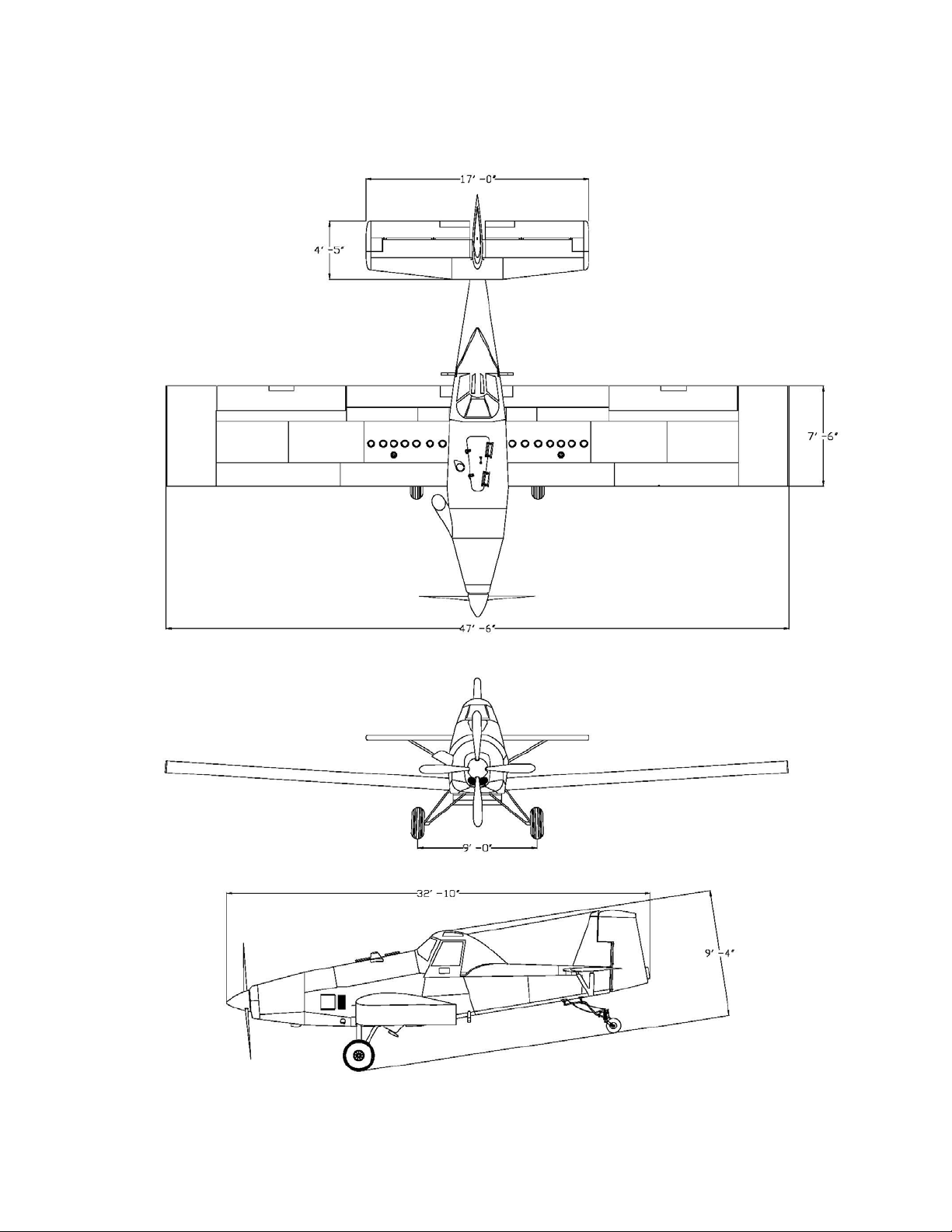
Figure 1-1: Aircraft 3-view .......................................................................................7
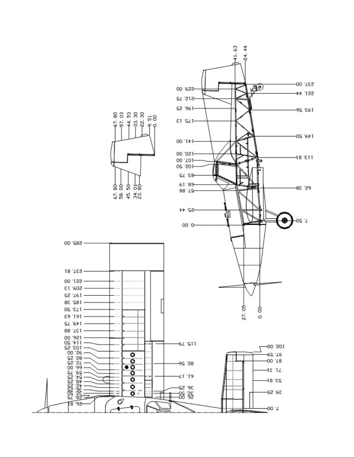
Figure 1-2: Aircraft Stations.....................................................................................8
Effective: 03/26/2010 page 1-1
Page 10
THRUSH AIRCRAFT, INC – MODEL S2R-G10
AIRCRAFT MAINTENANCE MANUAL
GENERAL DESCRIPTION
The Thrush Aircraft Inc Thrush S2R-G10 is designed especially for agricultural flying. It is a
monoplane featuring a full cantilever low wing and all metal construction. The design and
construction of the airframe components assure structural integrity, flight safety, and
minimum maintenance requirements. The Thrush S2R-G10 is designed for the highest
crash load factors in the industry. Safety and reliabilit y of operation and maximum pilot crash
protection are proven and effective features of the design. The high strength overturn
structure is a proven design. The fuselage and overturn structure, constructed throughout of
chrome-moly steel tubing, are immensely strong in the cockpit area.
CONTACT INFORMATION
For further information related to this manual, please contact our Product Support Manager
at (229) 883-1440 extension 219.
PRINCIPAL DIMENSIONS
GENERAL
Wing Span..................................... 47.50 feet
Overall Length ............................... 32.83 feet
Height To Top Of Canopy.............. 9.33 feet
Main Gear Tread............................ 9.00 feet
Main Gear To Tail Wheel............... 19.20 feet
WEIGHT & BALANCE
C. G. Range (See Airplane Flight Manual for pertinent data)
Forward Limit at 6,000 pounds is 26.5
Forward Limit.................................
Aft Limit .........................................
Datum............................................
inches aft of datum. It is 24.0 at 4,000
pounds with straight line variation between.
Aft Limit at all weights is 30.0 inches aft of
datum
Datum Is The Leading Edge Of The Wing.
WING
page Effective: 03/26/2010 1-2
Type ............................................... Full Cantilever
Airfoil Section ................................. NACA 4412
Dihedral.......................................... 3.50 Degrees
Aileron Travel
Up........................................ 21 Degrees ±1 Degree
Down ................................... 17 Degrees ±1 Degree
Flap Travel: Down .......................... 15 Degrees ±1 Degree
Page 11

THRUSH AIRCRAFT, INC – MODEL S2R-G10
AIRCRAFT MAINTENANCE MANUAL
HORIZONTAL STABILIZER AND ELEVATORS
Span............................................... 204 Inches (17')
Elevator Travel
Up........................................ 27 Degrees ±1 Degree
Down................................... 17 Degrees ±1 Degree
Trim Tab Travel
Up........................................ 8 Degrees ±1 Degree
Down................................... 22 Degrees ±1 Degree
VERTICAL STABILIZER AND RUDDER
Vertical Fin Offset........................... 0 Degrees ±1 Degree Left and Right
Rudder Travel ................................ 19 Degrees ±1 Degree Left and Right
AREAS
Wing............................................... 356.3 Square Feet
Aileron (Each)................................. 23.4 Square Feet
Flaps (Each)................................... 15.3 Square Feet
Stabilizer......................................... 39.3 Square Feet
Elevators ........................................ 20.4 Square Feet
Elevator Tabs (Each)...................... 1.3 Square Feet
Vertical Fin .................................... 9.4 Square Feet
Rudder ........................................... 12.2 Square Feet
SUPPLIER FURNISHED COMPONENT MANUALS
COMPONENT MANUAL PART #
TPE331-G10 Maintenance Manual 72-00-27
TPE331-G10 Parts Manual 72-01-16
Propeller Owner’s Manual N/A
Note: Should there be a conflict between the information in this manual and that in the
manuals for component parts, the information in the component part manual takes
precedence.
Effective: 03/26/2010 page 1-3
Page 12

THRUSH AIRCRAFT, INC – MODEL S2R-G10
AIRCRAFT MAINTENANCE MANUAL
AIRCRAFT STRUCTURE
FUSELAGE
The fuselage is comprised of a welded
tubular steel frame, fiberglass hopper, and
detachable skins. An overturn structure
forms an integral part of the fuselage
frame. The frame structure is fabricated
from 4130 chrome-moly seamless steel
tubing, and the fittings, bushings, brackets,
and so forth are 4130 steel sheet.
As a corrosion preventative, hot linseed oil
is pumped throughout the entire welded
structure. On an average, 12 gallons are
pumped into the frame and 11 to 11 ½
gallons drain out, leaving a residual interior
coating on all members. The exterior of
the frame is sandblasted, etched, and
primed, which is followed by two coats of
polyurethane paint that is resistant to
chemical reaction.
The fuselage is covered with heat treated
Alclad panels attached with camloc
fasteners. Side skins can be removed
using only a screwdriver, thus exposing
the fuselage frame for thorough cleaning
and inspection. All skins are supported
clear of the fuselage tubing to prevent
accumulation of corrosive chemicals.
Each skin panel is etched, primed, and
painted before assembly to ensure
complete coverage. All bottom fuselage
skins around the hopper opening and aft to
the tail post are made of stainless steel.
The skin fasteners in the high corrosion
areas are also stainless steel.
WING
The wing has a constant chord of 90
inches, and is all metal, full cantilever
design. The massive main spar is a
tension field beam structure constructed
from Alclad webs and high strength heattreated steel caps. All wing skins, ribs, and
leading edges are constructed from Alclad
heat-treated material. The leading edge
structure is made especially strong to
minimize denting and is riveted with
universal rivets for strength. The fuel
tanks, which are located in the inboard
section of the wing, are an integral part of
the structure. Close pitch riveting of the
seams, substantial reinforcement, and
flexible sealants minimize chances of
rupture in crash conditions. Drain holes
are provided in adjacent bays to prevent
accumulation of fuel in the event of a leak.
The ailerons and flaps are all metal
construction and are hinged on ball
bearings. The flaps are electrically
operated by push rods and are completely
sealed against chemical entry. Flap
hinges are stainless steel.
EMPENNAGE
The horizontal stabilizer, elevator, rudder
and vertical fin are an all-metal structure.
All skins, ribs and leading edges are
constructed from alclad material. The
movable surfaces are hinged on sealed
bearings that can be easily replaced. The
rudder and the elevator have aerodynamic
balances that are protected by overhangs
on the fixed surfaces.
COCKPIT
There are two choices of the enclosed
cockpit canopies for the Thrush S2R-G10
(1) the SINGLE cockpit canopy or (2) the
DUAL cockpit canopy. The overturn
structure of both is exceptionally strong
and welded to "hard points" in the fuselage
frame. The forward bracing supports the
windshield support channels and is we lded
to a lateral tube that is curved to provide
more head clearance. The fiberglass
canopy shell has extra thickness on the
top portion and is well attached to the extra
large steel tube structure so that it will
serve as a skid in case of overturn. The
large canopy doors permit easy entrance
to one or both cockpits. The doors should
not be removed for flight, as the aircraft
performance will be degraded. The
cockpit seat belts are anchored to the seat
structure, and the shoulder harnesses are
secured to a steel channel at the bottom of
1-4
page Effective: 03/26/2010
Page 13

THRUSH AIRCRAFT, INC – MODEL S2R-G10
AIRCRAFT MAINTENANCE MANUAL
the seat structure. The seats adjust
vertically. The rudder pedals adjust fore
and aft. The windshield is a three-piece
construction. The center section is
tempered safety plate glass for better
resistance to scratching and bird strikes.
The windshield side panels are Plexiglas
and are curved to provide streamlining.
AIRCRAFT SYSTEMS
HYDRAULIC SYSTEM
The hydraulic system consists of two
master brake cylinders with hydraulic lines
connecting the master cylinders to the
wheel brake cylinders. Applying toe
pressure on the rudder pedals actuates the
master cylinders, which are located above
and just aft of the pilot’s rudder pedals. A
small reservoir is incorporated within each
master cylinder to supply the system with
brake fluid.
POWER PLANT & PROPELLER
The Thrush S2R-G10 is powered by the
Garrett (Honeywell) TPE331-10 turbo-prop
engine. The propeller is a constant speed
Hartzell HCB4TN-5NL hub with LT10890N
blades, McCauley 4HFR34C653 hub with
L106FA-0 blades, or McCauley
4HFR34C662 hub with L108FA blades.
This combination provides takeoff power of
900 BHP at 1,500 RPM. The engine
mount is a welded chrome-moly tube truss,
stress relieved after welding. The engine
is attached to the mount through vibration
isolators.
Accessibility for servicing and inspection in
the engine compartment is exceptional, as
cowl panels are easily removed for full
access.
FUEL SYSTEM
A 228-gallon (useable) fuel supply is
available for the Thrush S2R-G10. One
hundred fifteen gallons of fuel is contained
in an integral wing tank (wet wing) just
outboard of the wing root. The left wing
and right wing fuel tanks are
interconnected through a 4.5 U.S. gallon
header tank that is located in the fuselage.
The fuel supply line to the engine is routed
from the header tank outlet finger screen
through a fuel shutoff (on/off) valve to an
electric driven fuel boost pump.
The electrically driven fuel boost pump
provides boosted fuel pressure to the
engine during starting. The electric driven
fuel boost pump discharge is then routed
through a 25-micron main fuel filter to the
engine fuel control.
The fuel tank vent system is designed to
keep the fuel spillage to a minimum. The
fuel tanks are vented through tubing
connected at both the inboard and
outboard ends of the individual fuel tanks
to the centrally located vent system in the
fuselage. Ram air enters a vent scoop, on
the fuselage, under the left wing and
pressurizes the vent system to maintain
positive pressure on the fuel tanks. The
vent system is provided with two quick
drains, located on the fuselage under each
wing, to drain any fuel that might have
gotten into the tanks outboard vent lines.
The fuel quantity gauge is located on the
lower left instrument panel. The fuel
quantity indicating system consists of two
transmitters, one indicator gauge, and an
L/H or R/H tank fuel quantity selector
switch. A transmitter installed in each wing
tank transmits an electrical signal to the
single fuel quantity indicator. The
instrument reads the left or right fuel tank
singularly, as chosen by the fuel quantity
selector switch, adjacent to the fuel
quantity indicator gauge on the instrument
panel.
The two fuel tanks are serviced through
filler ports located on the top of each wing.
The filler ports incorporate security chains
to prevent the loss of the fuel caps.
Service the aircraft from refueling facilities
that utilize proper ground handling
equipment and filter systems to remove
Effective: 03/26/2010 page 1-5
Page 14

THRUSH AIRCRAFT, INC – MODEL S2R-G10
AIRCRAFT MAINTENANCE MANUAL
impurities and water accumulation from the
bulk fuel. If filtering facilities are not
available, filter the fuel through a quality
high-grade chamois. Fuel tanks should be
serviced after the last flight of each day to
reduce condensation and allow any
entrapped water accumulations to settle to
the fuel system drains, to be removed,
prior to the next flight.
Prior to the first flight of the day the wing
tanks, header tank and fuel filter should be
drained to check for the presence of water
or sediment in the fuel system. If there is a
possibility, at any time, that any tank may
contain water, the header tank and fuel
filter should be drained as necessary to
ensure no water exists in the fuel system.
For fuel system servicing information, refer
to Section 2.
LANDING GEAR, WHEELS &
BRAKES
The main landing gear is a welded truss of
streamlined chrome-moly steel tube. The
left main gear and the right main gear are
symmetrical. The main tires are 29 x 11
on Cleveland 40-133 wheels with 30-98
dual caliper disc brakes. Inboard mounted
elastomeric shock struts absorb landing
and taxi stresses. The brake system has
individual toe brakes and individual park
brakes. The use of a special N-513
compound cup in each master cylinder
permits the use of MIL-H-5606, a heavyduty aviation hydraulic fluid. The tail gear
uses a 12.5 x 4.5 tire and tube mounted in
a symmetrical fork with a spring steel
shock absorber. The tailwheel is normally
locked but can be unlocked for fullcastering as the airplane is steered with
the brakes.
FLIGHT CONTROLS
The flight controls are of conventional
design employing extensive use of ball
bearings for low friction and smoothness of
operation. The aileron and elevator
controls are push rod systems and rudder
control is through tension cables. The
elevator trim control is actuated by a lever
that moves the tab to the desired position
through push rods. The wing flaps are
operated electrically and controlled by a
switch located on the left side of the
cockpit. The rudder controls are interconnected by springs to the aileron system
so that a wing may be lifted with the rudder
alone.
INSTRUMENTS
The standard instruments are located on
three separate panels: An upper panel, a
left panel, and a right panel. The left panel
contains a clock, oil temperature, hour
meter, fuel pressure, oil pressure, torque
gauge and fuel quantity gauges. The right
panel contains a voltmeter, ammeter, and
circuit breakers. The upper panel contains
propeller tachometer and a standard flight
instrument package.
ELECTRICAL SYSTEM
The standard 28 volts 250 amp electrical
system consists of the generating and
starting system, the wiper/washer system,
the navigation lights and the strobe lights.
The navigation lights, strobe lights, landing
lights, working lights and the air conditioner
system are optional. The electrical system
obtains power from dual 28-volt batteries
and one a starter-generator. An external
power receptacle is standard equipment
and may be used for connecting a 28-volt
ground power unit to the aircraft for engine
starting or maintenance. The ground start
system utilizes the master relay so that
starting is accomplished by engaging the
starter switch.
AIRCRAFT WEIGHT & BALANCE
Refer to S2R-G10 Flight Manual for
detailed aircraft weight and balance
information.
page 1-6 Effective: 03/26/2010
Page 15
THRUSH AIRCRAFT, INC – MODEL S2R-G10
AIRCRAFT MAINTENANCE MANUAL
Figure 1-1: Aircraft 3-view
Effective: 03/26/2010 page 1-7
Page 16
THRUSH AIRCRAFT, INC – MODEL S2R-G10
AIRCRAFT MAINTENANCE MANUAL
page Effective: 03/26/2010 1-8
Figure 1-2: Aircraft Stations
Page 17

THRUSH AIRCRAFT, INC – MODEL S2R-G10
AIRCRAFT MAINTENANCE MANUAL
Effective: 03/26/2010 page 1-9
Page 18

THRUSH AIRCRAFT, INC – MODEL S2R-G10
AIRCRAFT MAINTENANCE MANUAL
SECTION 2
SERVICING & INSPECTION
TABLE OF CONTENTS
SERVICING & INSPECTION.......................................................................................... 3
GENERAL DESCRIPTION
GROUND HANDLING............................................................................................... 3
TOWING............................................................................................................... 3
TAXIING............................................................................................................... 3
PARKING ............................................................................................................. 3
MOORING............................................................................................................ 3
JACKING.............................................................................................................. 3
LEVELING............................................................................................................ 3
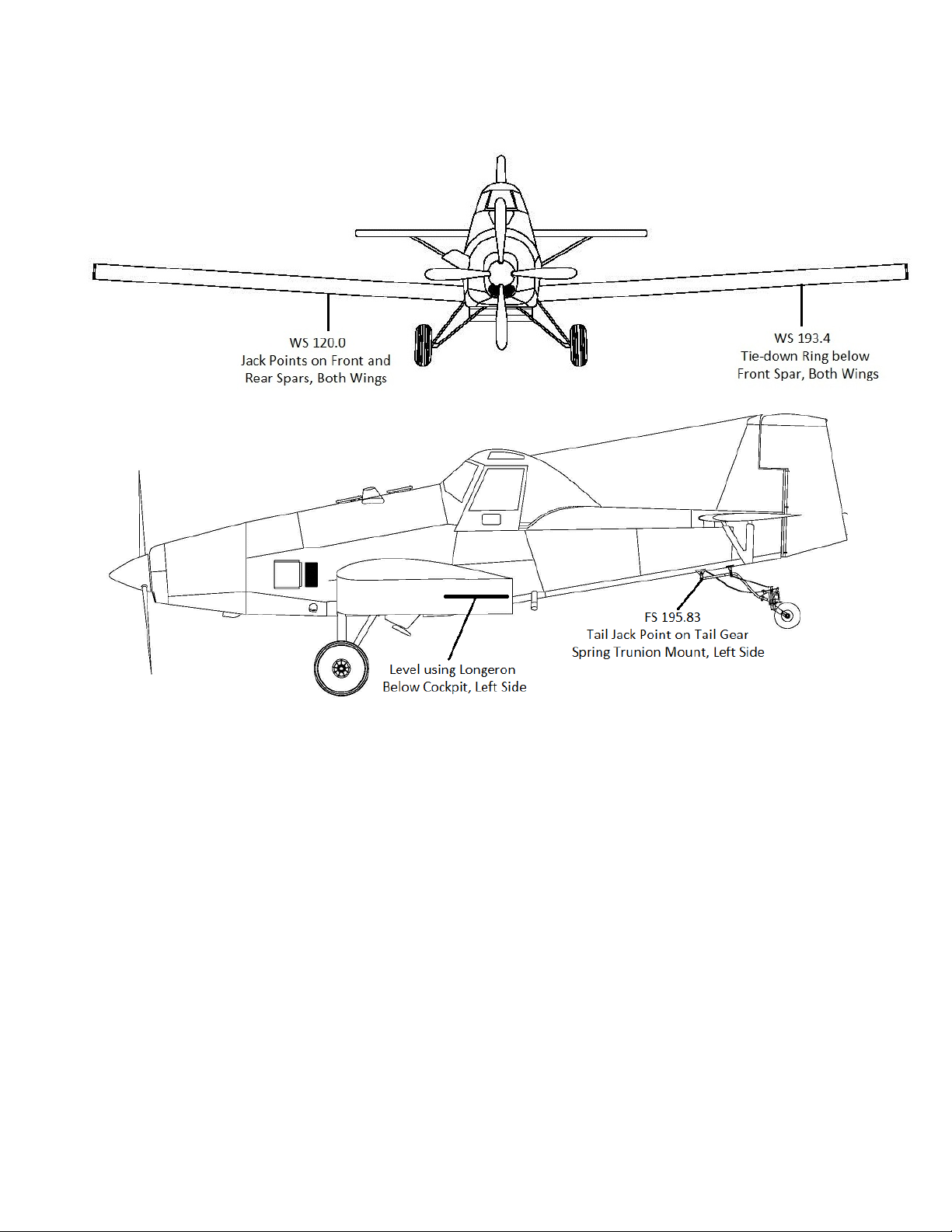
Figure 2-1: Tie Down and Jack Points............................................................ 4
WEIGHING........................................................................................................... 5
Calculated Weight........................................................................................... 5
Weighing the Airplane..................................................................................... 5
COLD WEATHER OPERATION................................................................................ 6
COLD WEATHER MAINTENANCE HINTS .......................................................... 6
GROUND EMERGENCY PROCEDURES................................................................. 7
ENGINE FIRES....................................................................................................7
ELECTRICAL FIRES............................................................................................ 7
GROUND OPERATION OF ENGINE ......................................................................... 7
EXTERIOR PRE-START CHECK ........................................................................ 7
PRE-START CHECKLIST.................................................................................... 7
COCKPIT PRE-START CHECK........................................................................... 7
STARTING ENGINE............................................................................................. 8
SYSTEM AND COMPONENT SERVICING............................................................... 9
HYDRAULIC SYSTEM ......................................................................................... 9
ENGINE OIL SYSTEM.......................................................................................... 9
FUEL SYSTEM...................................................................................................10
Figure 2-2: Fuel System............................................................................... 11
DEFUELING............................................................................................. 12
LANDING GEAR, WHEELS & BRAKES............................................................. 12
Tires ..............................................................................................................12
MLG Shock Struts ......................................................................................... 12
BRAKE BLEEDING ......................................................................................13
INSPECTION ........................................................................................................... 13
INSPECTION CHECK LIST ................................................................................ 13
GENERAL INSTRUCTIONS........................................................................... 13
Figure 2-3: G10 Servicing and Inspection Guide........................................ 14
Effective: 03/26/2010 Page 2-1
Page 19

THRUSH AIRCRAFT, INC – MODEL S2R-G10
AIRCRAFT MAINTENANCE MANUAL
Table 2-2: INSPECTION CHECK LIST............................................................14
A: Propeller...................................................................................................13
B: Engine Externals ......................................................................................15
C: Engine Oil System....................................................................................16
D: Engine Fuel Xystem.................................................................................17
E: IGNITION SYSTEM..................................................................................17
F: Airframe Fuel System...............................................................................17
G: Main Landing Gear...................................................................................19
H: Hydraulic System .....................................................................................19
J : Tail Gear ..................................................................................................19
K: Fuselage Skins.........................................................................................21
L: Hopper......................................................................................................21
M: Wings.......................................................................................................21
N: Fuselage Frame.......................................................................................22
P: Control Systems.......................................................................................23
Q: Empennage..............................................................................................24
R: Ailerons and Flaps....................................................................................24
S: Cockpit .....................................................................................................25
T: Electrical System......................................................................................26
BATTERY MAINTENANCE......................................................................................26
AIRFRAME MAINTENANCE........................................................................................26
CORROSION CONTROL.........................................................................................26
WINDSHIELD...........................................................................................................28
HOPPER REPAIR ....................................................................................................28
FUEL TANK REPAIR...............................................................................................28
Table 2-3: Torque Chart....................................................................................29
LUBRICATION..............................................................................................................30
Figure 2-4: Lubrication Chart (9 pages)..............................................................30
Page 2-2 Effective 03/26/2010
Page 20

THRUSH AIRCRAFT, INC – MODEL S2R-G10
AIRCRAFT MAINTENANCE MANUAL
SERVICING & INSPECTION
Standard procedure for ground handling,
servicing, inspection, airframe
maintenance, lubrication, and storage are
included in this Section. Adherence to
these procedures on a scheduled basis
can save many hours of maintenance and
aircraft down time. When a system
component requires service or
maintenance other than that outlined in
this Section, refer to the applicable Section
of this manual for complete information.
GROUND HANDLING
TOWING
Movement of the aircraft on the ground
may be accomplished as follows:
a. Pull and guide the aircraft by means of
a tow bar with the tail wheel unlocked.
b. Attach a rope harness to the main
gear when there is a need to tow the
aircraft forward through snow or over
soft and/or muddy ground.
PARKING
Head the aircraft into the wind and set the
parking brake. Do not set the parking
brake during cold wet weather because the
accumulated moisture may freeze in the
brakes. Do not set the parking brake if the
brakes are overheated. Install the internal
control lock and place the chocks under
each main wheel.
MOORING
Reference Fig. 2-1
Park aircraft as previously outlined. In
winds up to 20 knots, secure the aircraft at
the wing tie down rings. For winds above
20 knots, tie the tail and main gear as well
as the wings. Install external control
surface locks. The aircraft should be
placed in a hangar when wind velocity is
predicted to exceed 50 knots. When
mooring the aircraft, use 3/4-inch manila or
nylon rope. A clove hitch or other anti-slip
knot should be employed. If a manila rope
is used for tie down, allow enough slack to
compensate for shrinkage of the rope fiber
without damaging the aircraft.
TAXIING
Before attempting to taxi the aircraft,
maintenance personnel should be checked
out by qualified personnel. When it is
determined that the propeller area is clear,
apply the power to start the taxi roll and
perform the following:
c. Push the stick full forward to unlock
the tail wheel.
d. Taxi a few feet and check the brake
operation.
e. While taxiing, make slight turns to
determine that the tail wheel steering
is operative.
f. Avoid taxiing over ground covered with
loose stones, gravel, or other loose
material that may cause foreign object
damage to the propeller or to other
aircraft in the area.
JACKING
Reference Fig. 2-1
Jack points are provided on each main
spar and located at wing stations 120 &
193.38. When using the jack points to lift
the aircraft, all hopper loads should be
removed. (Fig. 2-1) A jack point is also
provided on the tail wheel trunnion attach
fitting on the lower left longeron.
LEVELING
Reference Fig. 2-1
The aircraft may be leveled by raising the
tail to an approximate level flight position
by supporting the tail on a stable jack or
platform. Adjust the height of the tail wheel
until the left-hand lower longeron located
under the pilot’s cockpit is level. The lower
left side panel must be removed for access
to the leveling longeron.
Effective: 03/26/2010 Page
2-3
Page 21
THRUSH AIRCRAFT, INC – MODEL S2R-G10
AIRCRAFT MAINTENANCE MANUAL
Figure 2-1: Leveling, Tie Down and Jack Points
Page 2-4 Effective 03/26/2010
Page 22

THRUSH AIRCRAFT, INC – MODEL S2R-G10
AIRCRAFT MAINTENANCE MANUAL
WEIGHING
Calculated Weight
The weight and center of gravity (C.G.) of
the airplane as it left the factory is supplied
with all the other paperwork.
Slight changes to the aircraft that do not
significantly alter the weight or C.G. can be
ignored, but judgment must be used when
doing so. A change weighing a pound in
the aft fuselage may be more significant
than a 5# change under the cockpit.
For changes that do significantly affect the
weight or C.G., the new empty weight and
C.G. can generally be calculated and
logged in the log book. To do this you
must know the weight change (+ for
added, - for subtracted) and its distance, in
inches, from the aircraft datum (wing
leading edge), “+” being aft of the datum
and “-“being forward.
*NOTE*
Center of Gravity (C.G.) location is
NOT the same as fuselage station.
The existing empty weight and C.G.
produces a moment by multiplying the two
together, and all three should be logged.
Changes to the aircraft will also have a
weight and location for their C.G., which
will give their moment when multiplied
together.
To determine the new empty weight, the
existing weight and the weight change are
totaled. To find the new C.G., the existing
moment and the moment change are
totaled and this new moment is divided by
the new empty weight.
For example:
C.G. of equipment = -23.5 (ie. forward
of wing leading edge)
Moment change = 17 x (-23.5) =
- 400 in.#
New weight: 4,723 + 17 = 4,740#
New moment: 120,106 – 400 =
119,706 in.#
New C.G.: 119706 ÷ 4740 = 25.25” (aft
of datum)
Weighing the Airplane
New weight and C.G. due to large weight
changes, installations that are difficult to
determine the C.G. of, or multiple small
changes should generally be determined
by re-weighing the airplane.
The airplane must be in a ready to fly
condition during weighing, except that the
fuel tanks may hold unusable fuel (1.5
GAL. per side).
Three scales will be needed for this
operation: two with about a two ton
capacity and one with a half ton capacity.
These scales need to be in good condition
and calibrated within the past year.
The two large scales are placed under the
MLG tires, and the small scale is placed
under the tailwheel. The airplane must be
level during this process (see LEVELING,
above), which will require a tail stand. The
new weight is simply the total of the three
scale readings, unless the tail stand had to
be placed on the rear scale. If this was
done, the weight of the tail stand and any
shims must be subtracted from the aft
scale reading. This is not necessary if the
scale was between the tailwheel and the
stand.
Existing weight = 4,723#
Existing C.G. = 25.43”
Existing moment = 4723 x 25.43 =
120,106 in.#
Added equipment weight = 17#
Effective: 03/26/2010 Page
2-5
The new moment is the sum of the main
gear scale readings multiplied by 3.10”
(the distance the MLG axles are behind
the wing leading edge) plus the rear scale
reading (adjusted for tare as necessary)
multiplied by 232.9”. The new empty
Page 23

THRUSH AIRCRAFT, INC – MODEL S2R-G10
AIRCRAFT MAINTENANCE MANUAL
weight C.G. is the total moment divided by
the total weight.
For example:
Left MLG scale reading = 2,127#
Right MLG scale reading = 2,105#
Tailwheel scale reading = 472#
Tare weight (ie. tail stand and shims if
placed on top of the scale) = 65#
New empty weight: 2127 + 2105 + 472
– 65 = 4,639#
New moment: (4232 x 3.1) + (407 x
232.9) = 107,910 in.#
New C.G.: 107910 ÷ 4639 = 23.26”
COLD WEATHER
OPERATION
Aircraft operation in cold weather creates a
need for additional maintenance practices
and operating procedures that are not
required in moderate temperatures.
Whenever possible, shelter the aircraft in a
heated hangar to prevent frost, ice, or
snow accumulation that requires added
maintenance time to remove. These
weather elements, if allowed to
accumulate only a fraction of an inch in
thickness on the critical airfoils and control
surfaces, seriously degrade aircraft lift and
flight control effectiveness. The possibility
of aircraft system failures is increased
when the aircraft is parked where wind
driven snow or freezing rain can be forced
into various openings of the aircraft. If the
aircraft is to be moored outside in extreme
cold, the battery should be kept fully
charged to prevent freezing. Make certain
that all vents, air inlets, and so forth are
covered.
Locating the aircraft inside a heated
hanger is the most effective method of
preheating the aircraft. The use of an
external power unit is recommended to
conserve the battery.
COLD WEATHER
MAINTENANCE HINTS
The information that follows is intended
only for the purpose of supplementing the
existing information in this manual when
operating the aircraft in very cold weather.
Keeping the aircraft in top maintenance
condition during cold weather cannot be
over stressed.
BATTERY: The batteries should be
maintained at full charge during cold
weather to prevent freezing. After adding
water to the battery in freezing
temperatures, charge the battery to mix
the water and electrolyte. A frozen battery
may explode when subjected to a high
charge rate. Corrosive damage to the
area adjacent to an exploded battery will
result if the electrolyte solution is not
removed immediately. Instructions for
removing spilled electrolyte are provided in
this Section. The battery should be
removed and stored in a warm place if the
aircraft is to remain idle for an extended
period of time.
FUEL SYSTEM: In the fuel system,
condensation is more likely to occur in cold
weather due to a more rapid and positive
division of moisture content from other fuel
constituents. If at all possible, use fueling
facilities that filter moisture from the fuel. If
fueling facilities with filters are not
available, filter the fuel through a good
quality chamois. Fill the tanks with correct
grade of fuel as soon as possible after
landing to reduce the possibility of
condensation and ice formation in the
tanks. Fuel extracted from fuel header
tank drain before starting deserves a
closer examination when the aircraft is
being operated in cold weather.
POST FLIGHT MAINTENANCE: Cold
weather operation demands procedures
that are in addition to normal Post Flight
Maintenance Procedures. Fill the fuel
tanks immediately after flight. If shelter is
Page Effective 03/26/2010 2-6
Page 24

THRUSH AIRCRAFT, INC – MODEL S2R-G10
AIRCRAFT MAINTENANCE MANUAL
not available, tie the aircraft down and
install covers on all vents, openings, etc.
as required.
GROUND EMERGENCY
PROCEDURES
Emergency procedures must be
accomplished as rapidly as possible,
should an emergency arise. It is
suggested that steps pertaining to each
emergency be committed to memory in
order to accelerate the procedure and
minimize any possible damage.
ENGINE FIRES
If a fire develops in the engine area during
engine start, continue to attempt to start
the engine in an attempt to blow the fire
out. If the fire persists, proceed as follows:
a. Mixture Control - Idle Cut Off
b. Starter Switch - Off
c. Master Switch - Off
d. Fuel Shutoff Valve - Off
e. Abandon the aircraft
weather from the wing, the tail, and the
control surfaces. Check that the control
surfaces contain no internal accumulations
of ice. Remove the inlet and exhaust
covers, if fitted. If night flight is planned,
check the operation of all lights and have a
flashlight available.
After a complete visual inspection has
been accomplished, the following checklist
may be used for the external prestart
check. The aircraft should be headed into
the wind and should have the wheel
chocks in place.
PRE-START CHECKLIST
a. A fire extinguisher must be readily
available in the event of an engine
fire.
b. Check the engine oil level. Assure
that the oil system has been serviced
with the correct grade of oil.
c. Verify that the internal control lock
has been removed and that the
controls operate freely.
d. Set the parking brake.
ELECTRICAL FIRES
Circuit breakers will automatically trip and
stop the current flow to a shorted circuit.
However, as a safety precaution in the
event of an electrical short circuit or fire,
turn the battery switch to off. Use a fire
extinguisher approved for electrical fires to
extinguish any flame. Do not leave the
aircraft unattended so long as there is any
evidence of fire or hot spots.
GROUND OPERATION OF
ENGINE
Reference Section 4
EXTERIOR PRE-START CHECK
Visually check the aircraft for general
condition. Verify that all CamLocs on the
skin panels are fastened. Remove all
accumulations of frost, ice, or snow in cold
e. Check the fuel quantity in both tanks.
f. Set the trim tabs for takeoff.
g. Clear the area of all personnel.
COCKPIT PRE-START CHECK
a. Verify that the internal control lock has
been removed and that the controls
operate
b. Place all switches in the OFF position.
c. Set the parking brake.
d. Check the fuel quantity indication in
both tanks.
e. Set the trim tabs for takeoff.
Effective: 03/26/2010 Page
2-7
Page 25
THRUSH AIRCRAFT, INC – MODEL S2R-G10
AIRCRAFT MAINTENANCE MANUAL
f. Turn Battery Switch ON, or to EXT
PWR position if external power will be
used to start the engine.
STARTING ENGINE
Use the following procedure to start the
G10 engine:
a. Power Lever – Flight idle position.
*NOTE*
Power lever must be in flight idle
position prior to and during start
sequence to prevent propeller
from coming off start lock during
starting.
b. Speed Lever – Low RPM position
c. Engine Fuel Switch – Cycle to off,
then center position
d. Fuel Valve – ON
e. Fuel Aux Pump – ON
f. Fuel Inlet Pressure Indicator –
CHECK 8 PSIG minimum
CAUTION
Do not attempt an engine start
without the propeller being on
the start locks.
*NOTE*
Engine starts can be made with the
aircraft battery power, or with
auxiliary electrical power. However,
it is recommended that an auxiliary
power unit be used when ambient
air temperature is ten degrees F. or
below. Ensure that ground power
unit (aux power) is regulated to 28
volts dc, 800 amperes during start
cycle.
To accomplish the check, do the following
during starting:
1) NTS Light – PRESS to test
2) Unfeathering Pump Switch – ON
3) NTS Check Switch – ON
4) NTS Light – CHECK ON
5) Engine Starter – Ground position (Carry out normal start)
6) NTS Light – OUT when starter is engaged
7) NTS Light – ON at 10 to 30 percent RPM
h. Engine Starter – Ground position
i. Ignition Switch – ON at 10% RPM
minimum
CAUTION
Check ignition light on prior to
operating fuel switch.
j. Engine Fuel Switch – ON at 10%
RPM minimum
CAUTION
k. If light-off is not indicated within
ten seconds or 20% RPM, reject
the start by activating the
emergency shut-off lever.
l. Fuel Enrichment Switch – ON until
approximately 680 degrees EGT
(maximum during start is 770
degrees). Then regulate
enrichment switch to obtain
satisfactory RPM increase and
temperature.
CAUTION
g. Negative Torque System Check
The NTS system should be checked
during the first start of the day or if a
malfunction of the system is suspected.
2-8
Page Effective 03/26/2010
If RPM stops increasing prior to
40% or if EGT is approaching
limits (770 degrees C) and
rising rapidly, activate the
emergency shut-off lever.
Page 26

THRUSH AIRCRAFT, INC – MODEL S2R-G10
AIRCRAFT MAINTENANCE MANUAL
m. Engine Instruments – CHECK
1) RPM – 72% Minimum
2) Fuel Pressure – 8 PSIG Minimum
3) Oil Pressure – 40 PSIG Minimum
If oil pressure is not indicated
within ten seconds after lightoff, shut the engine down and
determine the cause
n. 13. Starter – OFF
o. 14. Generator – ON and charging
normally
p. 15. If NTS check was accomplished:
1) Unfeathering Pump Switch – OFF
2) NTS Check Switch – OFF
CAUTION
SYSTEM AND COMPONENT
SERVICING
Servicing procedures contained in this
Section are confined to those maintenance
actions that occur with routine frequency
and require a reasonably short period of
time to accomplish. Servicing practices
and maintenance of aircraft systems and
components that require less frequent
attention are contained in the appropriate
sections of this manual.
HYDRAULIC SYSTEM
Reference Section 3
The hydraulic system consists of two
master brake cylinders and the necessary
hydraulic lines connecting the master
cylinders to the wheel brake cylinders.
Applying toe pressure to the rudder pedal
actuates the corresponding master
cylinder, which in turn actuates the brake
caliper piston. Refer to Section Six for
brake servicing procedures.
ENGINE OIL SYSTEM
Reference Section 4
The oils that are specified for the
lubrication system can be found in the
applicable engine Maintenance Manual. It
is recommended for all turbo aircraft that
the oil be changed every 400 hours. The
oil system contains 9 U.S. quarts.
*NOTE*
The unfeathering pump draws oil
from the engine oil tank to actuate
the propeller. The oil from the
propeller subsequently drains into
the reduction gear box, not the
engine oil tank. If the unfeathering
pump has been operated prior to
checking the oil level in the tank,
pump the oil out of the gearbox and
into the oil tank by turning the
propeller 50 to 75 revolutions by
hand or by starter. During the
procedure, it is not uncommon to
experience some loss of oil
overboard through the vent.
The contents of the oil tank should be
checked within 10 minutes of the engine
shutdown. To do so, proceed as follows:
a. Unlock the filler cap and dipstick from
the filler neck on the oil tank.
CAUTION
Do not mix brands or types of oil,
since their chemical structures
may make them incompatible. If
different brands or types of oil
become mixed, drain and flush
the system and refill with new oil.
b. Check the oil tank contents against the
markings on the dipstick. Service as
required.
c. Compensate for the pitch attitude of
the aircraft to avoid over or under
servicing.
Effective: 03/26/2010 Page
2-9
Page 27

THRUSH AIRCRAFT, INC – MODEL S2R-G10
AIRCRAFT MAINTENANCE MANUAL
If the oil level is too low to register on the
dipstick due to possible excessive
consumption or if low or fluctuating oil
pressure noted, refer to the trouble
shooting section in your applicable engine
Maintenance Manual for the action to be
taken. After that has been accomplished,
proceed as follows to check the oil level.
d. Fill the oil tank to the appropriate
normal level. Record the quantity of
oil added to the system.
e. Install the filler cap and dipstick.
Ensure that the cap is securely locked.
f. Run the engine at idle for
approximately five minutes.
g. Check the oil level.
On engines which have remained
stationary for a period of 12 hours or more,
proceed as follows to check the oil level.
1) Start engine and run at idle speed for a minimum of two minutes.
must be conducted with the electrical fuel
auxiliary boost pump ON.
WARNING
GROUND THE AIRCRAFT TO A
PROPER GROUND AND THE
FUEL SERVICING EQUIPMENT TO
THE AIRCRAFT. SMOKING IN OR
AROUND THE AIRCRAFT DURING
REFUELING OPERATIONS IS
PROHIBITED. FIRE PROTECTION
EQUIPMENT MUST BE
IMMEDIATELY AVAILABLE.
To fuel the aircraft, proceed as follows:
a. Remove the fuel filler cap. Fill the tank
until the fuel level rises to the filler
neck (or to desired quantity). Install
the fuel filler cap and service the
opposite fuel tank.
* NOTE *
2) Shut the engine down.
3) Check the oil level.
FUEL SYSTEM
Reference Section 5
REFUELING:
(Ref. Fig. 2-2)
Refuel the aircraft with fueling facilities
that contain filters for removing the
moisture content from the fuel. If the
fueling facilities with filters are not
available, filter the fuel through a good
grade of chamois. The fuel tanks should
be serviced after the last flight of the day
to allow maximum time for the moisture to
reach the sumps and header tank.
Service the aircraft with Jet A, Jet B, JP4
or JP5. If jet fuel is not available, aviation
gasoline MIL-G-5572 (all grades) not in
excess of 250 gallons per 100 hours of
operation may be used for emergency fuel
operation. Total usage must be limited to
7000 gallons during any 3000 hour period.
Flight operations using aviation gasoline
Since the wing tanks are
interconnected through the header
tank, the fuel can flow from one
tank to another. Topping off both
wing tanks may be required more
than one time to assure that both
wing tanks are full.
b. After fueling is complete, check for
security of both fill port caps. Wash
any spilled fuel from the wing surface
with clean water.
FUEL DRAINS:
(Ref. Fig. 2-2)
Four fuel drain points are provided to allow
fuel draining in order to extract the moisture
sediment and other contamination entrapped
in the system. The drains are located at the
low point of each wing tank (aft inboard
bottom), the bottom of the header tank, and
the bottom of the firewall fuel filter (Fig. 2-2).
Also provided are two fuel vent drains, located
on each side of fuselage under the wings.
2-10
Page Effective 03/26/2010
Page 28

THRUSH AIRCRAFT, INC – MODEL S2R-G10
AIRCRAFT MAINTENANCE MANUAL
All fuel drains should be drained prior to the
first flight of the day. Drain a small quantity of
fuel into a transparent container to permit
inspection for the presence of moisture,
sediment or othere contaminants. If there is
any indication of contamination, the fuel
should be drained until all evidence of
contamination disappears.
CAUTION
Visually check that all drain
valves are closed after draining.
FUEL SYSTEM SCREENS:
(Ref. Fig. 2-2)
The airframe is equipped with five fuel
screens: 1/12 inch mesh finger strainers
in each wing tank outlet and a ¼ inch
mesh finger strainer installed in the outlet
fitting from the header tank. Inspect the
finger strainers annually or if the fuel
system is thought to have been or is
known to be contaminated with foreign
debris: i.e. moisture, debris or other
contaminants are noted in drained fuel
sample container, fuel source is known to
be contaminated etc.
REI NS T AL L T HE 2 5 FIREWA LL
MOUNTED FUEL FILTER:
(Ref. Fig. 2-2)
The main fuel filter
inspected, cleaned and reinstalled every
100 hours, or any time fuel system
contamination is suspected. Refer to
Section 5 for main fuel filter servicing
procedures.
Figure 2-2: FUEL SYSTEM
screen should be
(below)
Effective: 03/26/2010 Page
2-11
Page 29

THRUSH AIRCRAFT, INC – MODEL S2R-G10
AIRCRAFT MAINTENANCE MANUAL
WARNING
IF THE RED FUEL BYPASS
INDICATOR BUTTON HAS
POPPED OUT, INVESTIGATE
AND REMOVE THE CAUSE
OF THE FUEL OBSTRUCTION
BEFORE FURTHER FLIGHT.
REMOVE, INSPECT, CLEAN
OR REPLACE AND MICRON
FILTER ELEMENT. YOU MAY
THEN RESET THE RED
BYPASS BUTTON BY
PRESSING IT IN WITH
FINGER PRESSURE.
DEFUELING
During the defueling operation, jet fuel
fumes are present; therefore, extreme
caution must be exercised to prevent fire
hazards. To defuel the aircraft, use the
following procedure.
SMOKING ON OR AROUND
THE AIRCRAFT IS NOT
PERMITTED AT ANY TIME.
AIRCRAFT AND EQUIPMENT
GROUNDING PROCEDURES
MUST BE STRICTLY
ADHERED TO. FIRE
EXTINGUISHING EQUIPMENT
MUST BE IMMEDIATELY
AVAILABLE.
a. Ground aircraft to a proper ground
point and all defueling equipment or
containers to the aircraft.
b. Place a vented container of adequate
capacity under each of the three drain
points (header tank and two aft
inboard wings). Verify that the
containers are properly grounded to
the aircraft.
c. Open the drain valves and allow all
fuel to drain. When tanks are empty,
close the drain valves and move the
WARNING
fuel containers a safe distance from
the aircraft.
d. Verify that all the drain valves are
closed.
LANDING GEAR, WHEELS &
BRAKES
Reference Section 6
Check all gear assemblies for general
cleanliness, security of mounting, and
hydraulic leaks at prescribed inspection
intervals. Lubricate all lubrication points on
main and tail gear assemblies at
prescribed intervals.
TIRES
Tires should be inspected for proper
inflation, breaks, cuts, and foreign objects
in tread, flat spots and exposed cord.
Replace tire if there is any question of its
reliability. Proper inflation is necessary for
maximum tire life. Maintain 29x11-10 ply
rated main tire and tube pressure at a
minimum of 40 psi to a maximum of 62 psi,
depending on the load and runway
conditions. The 12.5 x 4.5-10 ply rated tail
wheel tire and tube pressure should be 55
psi maximum. The wheels and tires are
balanced assemblies. If tires are
suspected of being out of balance, they
may be balanced on automotive type
balancing equipment. If aircraft is out of
service, move the aircraft to rotate tires
every seven days to prevent flat spots from
developing.
MLG SHOCK STRUTS
Main landing gear shock struts are to be
inspected at the specified intervals. At
least annually they must be removed from
the aircraft, disassembled, cleaned and
inspected. Shock “biscuits” should be
replaced every 1000 hours or if they
develop cracks. Reinstall shock struts with
new hardware
2-12
Page Effective 03/26/2010
Page 30

THRUSH AIRCRAFT, INC – MODEL S2R-G10
AIRCRAFT MAINTENANCE MANUAL
BRAKE BLEEDING
Brake bleeding should be performed when
air is suspected of being entrapped in
brake lines. See Section 3 for brake
bleeding procedures.
INSPECTION
In Table 2-2 (next page), items to be
inspected and the maximum inspection
intervals are listed. Details of how to
check or what to look for are common
knowledge to licensed mechanics, but are
described generally below. Specific
checks can be found in relevant sections
of this manual.
INSPECTION CHECK LIST
Ref. Figure 2-3
GENERAL INSTRUCTIONS
a. Movable parts are to be checked for
lubrication, servicing, security of
attachment, binding, excessive wear,
safety, proper operation, proper
adjustment, correct travel, cracked
fittings, security of hinges, defective
bearings, cleanliness, corrosion,
deformation, sealing, and tension.
b. Fluid lines and hoses are to be
checked for leaks, cracks, dents,
kinks, chafing, proper bend radius,
security, corrosion, deterioration,
obstructions, and foreign matter.
c. Metal parts are to be checked for
security of attachment, cracks, and
metal distortion, broken spot welds,
corrosion, condition of paint, and any
other apparent damage.
d. Wiring is to be checked for security,
chafing, burning, defective insulation,
and loose or broken terminals, heat
deterioration, and corroded terminals.
e. Bolts in critical areas are to be
checked for correct torque, or when
visual inspection indicates the need for
a torque check. See Table 2-3, Torque
Chart.
f. Filters, screens, and fluids are to be
checked for cleanliness, contamination
and/or need of replacement at
specified intervals.
This Manual contains information on
aircraft systems and operating procedures
required for safe and effective
maintenance. It shall not be used as a
substitute for sound judgment.
*NOTE*
Certain chemicals cannot be
removed effectively by detergent
solutions. Special cleaning agents
are available for that purpose. It is
suggested that the chemical
suppliers be contacted for cleaning
agents that are suitable for those
special needs.
Inspection intervals are greatly influenced
by particular operational priorities,
operating conditions, environment, and
routine inspection results.
Perform the tasks shown in the following
Inspection Chart at the prescribed
intervals, or more often if necessary.
Effective: 03/26/2010 Page 2-13
Page 31
THRUSH AIRCRAFT, INC – MODEL S2RHG-T65 TURBO THRUSH
AIRCRAFT MAINTENANCE MANUAL
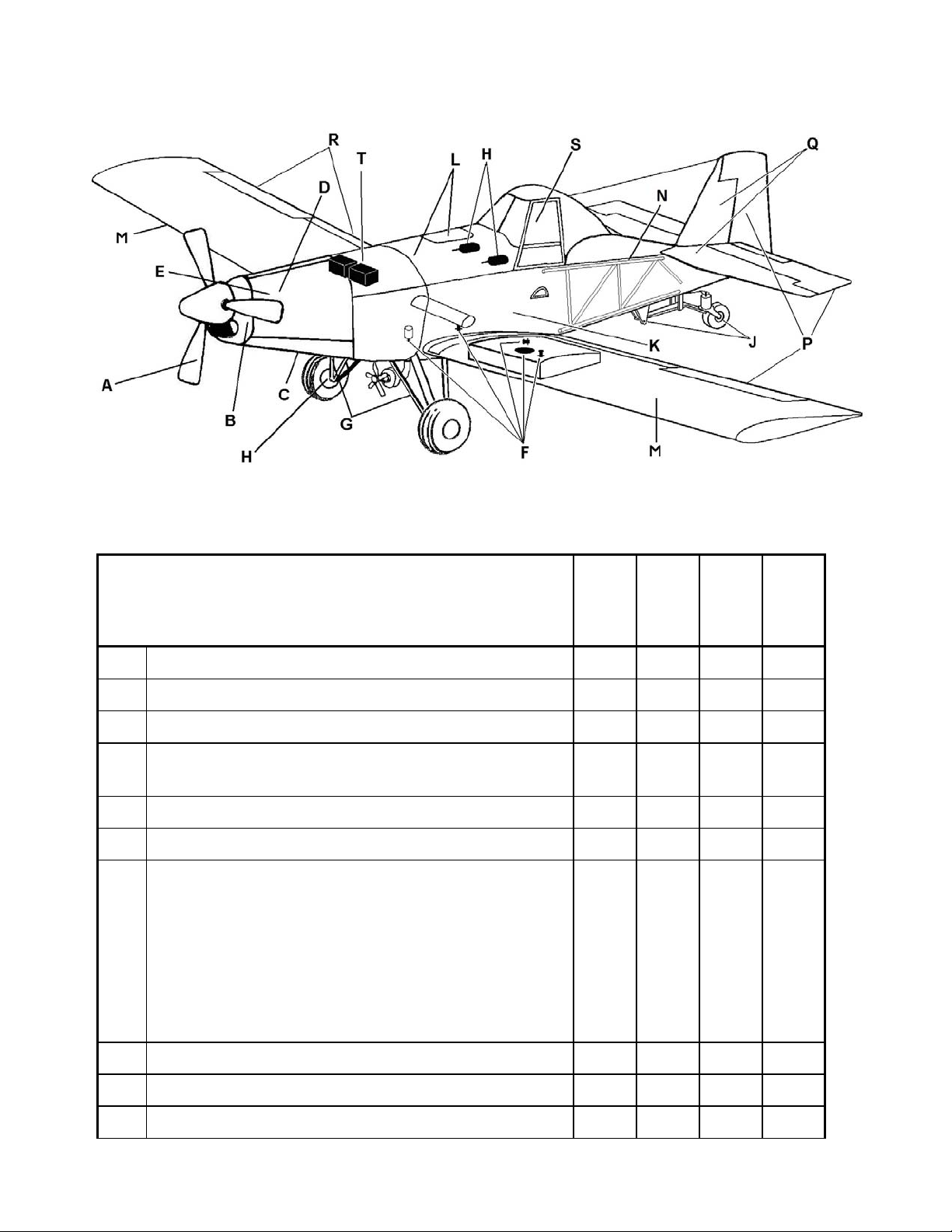
Figure 2-3: G10 Servicing and Inspection Guide
Table 2-2: INSPECTION CHECK LIST
A: PROPELLER
Refer to Hartzell Manual #139 Propeller Owner’s
Manual and Logbook or Appropriate McCauley
Maintenance Manual.
1. Remove the spinner and check for cracks. X
2. Check the back plate for cracks and corrosion. X
3. Check for grease and oil leaks. X
Check the hub bolts and balance screws of the
4.
blades for safety.
5. Inspect the blades for nicks and cracks. X
6. Inspect the hub parts for cracks and corrosion. X
For Hartzell only. Lubricate the propeller with
Aeroshell 6 grease only. Remove the rear “Zerk”
fitting from each blade clamp. Using a hand
operated grease gun, grease each forward fitting
7.
slowly. Lubrication is complete when grease
emerges in a steady flow with no air pockets or
moisture, and has the color and texture of the new
grease. Reinstalled the rear “Zerk” fittings.
Daily
X
X
50
hrs
hrs
100
hrs
400
8. Check counterweight bolts for safety. X
9. Check the propeller shaft seal for oil leaks. X
10. Reinstall spinner. X
Effective: 09/16/05 2-14
Page 32

THRUSH AIRCRAFT, INC – MODEL S2R-G10
AIRCRAFT MAINTENANCE MANUAL
B: ENGINE EXTERNALS
Refer to appropriate Garrett Maintenance Manual for
Pertinent Details on Engine Inspection.
Periodic Engine Inspection and Servicing should
be followed in accordance with the engine
1.
Periodic Inspection Requirements Table in the
engines’ maintenance manual.
Check tubing, wiring, control linkages and hose
2.
assemblies for evidence of wear, chafing, cracks,
and corrosion.
Check the tubing, wiring, control linkages, and
3.
hose assemblies for evidence of fuel and oil
leakage.
Check the tubing, wiring, control linkages, and
4.
hose assemblies for loose nuts and broken safety
wire.
50
Daily
X X X X
X
X
X
hrs
hrs
100
hrs
400
5.
6.
7.
8.
9.
10.
11.
12.
13.
Check the engine case for cracks, distortion and
corrosion.
Check the exhaust duct for cracks, security and
distortion.
Check the air inlet screen area for cleanliness,
cracks, and security.
Lubricate interconnecting rod ball ends, where
applicable.
Check engine mount for cracks, particularly in
welded areas. Check rubber isolators for splits,
cracks and deterioration. Check fasteners for
security.
Check the security of the accessories and
linkages.
Check the security of pneumatic lines.
Check for evidence of oil and fuel leaks in
accessory areas.
Check security and mounting of starter/generator.
Check brushes for wear.
X
X
X
X
X
X
X
X
X
Effective: 03/26/2010 Page 2-15
Page 33
THRUSH AIRCRAFT, INC – MODEL S2R-G10
e
AIRCRAFT MAINTENANCE MANUAL
14.
1.
B: ENGINE EXTERNALS (Continued)
Inspect and lubricate starter-generator drive
splines with Aeroshell 17 grease (MIL-G-21164)
*NOTE*
Initial inspection/lubrication at 100 hours.
Subsequent inspection/lubrication at 200 hour
interval.
C: ENGINE OIL SYSTEM
CAUTION
Do not mix different brands or types of
oil when changing oil or when
replenishing the oil between oil changes.
Check the oil level. Oil change recommended
every 400 hours.
* NOTE *
To avoid overfilling of oil tank, and high oil
consumption, an oil level check is recommended
within 10 minutes after engine shutdown. If more
than 12 minutes has passed, and the dipstick
indicates that oil is needed, start the engine and
run at idle speed for a minimum of two minutes,
and recheck oil level.
Daily
hrs
hrs
100
hrs
400
50
X
Daily
hrs
hrs
100
hrs
400
50
X X X
Chang
Oil
2. Check condition and security of oil filler cap.
Oil Filter – Remove, inspect and replace paper oil
3.
X
X
filter element.
* NOTE *
Thrush Aircraft, Inc. highly recommends utilizing a
S.O.A.P. (Spectrometric Oil Analysis Program). A
S.O.A.P. kit includes:
Page Effective 03/26/2010 2-16
1) New filter element “O” ring (if required), oil
sample kit, filter bottle and return packaging.
2) Analysis of filter and oil (if submitted).
3) Scanning Electron Microscope (SEM)
investigation of any debris found within the filter
to positively identify any possible bearing, cage,
shaft, or gear material
Page 34

THRUSH AIRCRAFT, INC – MODEL S2R-G10
AIRCRAFT MAINTENANCE MANUAL
C: ENGINE OIL SYSTEM (Continued)
Check the chip detector for continuity using a
suitable ohmmeter. An open circuit condition,
4.
which indicates no ferrous contamination at pole
tips, must exist.
Inspect oil cooler for damage, cleanliness, leaks,
5.
and security.
Inspect oil cooler scoop inlet area to ensure good
6.
airflow through cooler.
D. ENGINE FUEL SYSTEM
1. Check the fuel for presence of water. X X
Check the fuel pump for security and fuel
2.
leakage.
Engine Fuel Filter – remove, inspect and replace
3.
paper fuel filter element.
Daily
X
X
X
Daily
X
X
50
50
hrs
hrs
hrs
100
hrs
100
hrs
400
hrs
400
* NOTE *
On new aircraft, check the filter after each flight
until there is no evidence of contamination.
Check the filter after the first flight or ground run
when any upstream component is replaced.
Check the fuel control unit for security, linkage
4.
and pneumatic tubes.
For improved hot section durability. It is
recommended that the fuel nozzle assemblies are
5.
inspected and functional tested in accordance
with time limits set forth in the engines
appropriate maintenance manual.
E. IGNITION SYSTEM
Check the ignition exciter for security and
1.
condition.
Check the ignition cable for chafing, wear and
2.
security.
Check the spark igniters for cleanliness and
3.
erosion. Perform an operational test..
X
X X
50
Daily
X
hrs
100
X
X
hrs
hrs
400
Effective: 03/26/2010 Page 2-17
Page 35

THRUSH AIRCRAFT, INC – MODEL S2R-G10
AIRCRAFT MAINTENANCE MANUAL
F. AIRFRAME FUEL SYSTEM
Remove, inspect, clean, and re-install the
1.
airframe main 25-micron fuel strainer.
* NOTE *
On new aircraft, check the firewall fuel filter
after each flight until there is no evidence of
contamination. Check the filter after the first
flight or ground run when any upstream
component is replaced.
Using a suitable container, drain each wing tank,
header tank, airframe fuel filter bowl, and vent
2.
system drains (2 ea.). Check for any debris,
sediment, or water and take corrective action if
any is found.
Check the fuel boost pump for security and
3.
upstream fuel leakage.
Turn the fuel boost pump on and to check
4.
operation and the downstream fuel lines for leaks.
Daily
hrs
hrs
100
400
50
X X X
X
X
hrs
Check boost pump seals by observing overboard
5.
drain while pump is running and has the fuel
system pressurized.
Inspect the fuel lines and supports for security and
6.
signs of chafing.
Check the fuel tank gauges for proper operation.
7.
Rock the wings to slosh the fuel to see that the
pointers are free.
Check the fuel shutoff valve for leaks in both the
8.
open and closed positions. Ensure smooth valve
handle operation and lock-out function.
Check tightness of all fittings (tank and line
9.
connections) and appropriate use of safety wire.
10. Check header tank for security, leaks and chafing.
*NOTE*
When a problem is found, refer to section 5.
X
X
X
X
X
X
Page 2-18 Effective 03/26/2010
Page 36

THRUSH AIRCRAFT, INC – MODEL S2R-G10
AIRCRAFT MAINTENANCE MANUAL
G: MAIN LANDING GEAR
Check the main landing gear attach-fittings and
1.
pivot bolts. Replace bolts if worn.
Check the tires and tubes, wheels, and brake
2.
discs and lining for general condition.
Daily
X X
X X
50
hrs
100
3. Check the spindle for straightness and tightness. X
Inspect rubber shock biscuits for distortion, splits
or evidence of compound deterioration. Inspect
4.
shock strut attachment bolts and replace if worn or
X
distorted. Use proper close tolerance NAS bolts
for replacements, not AN hardware.
Check tripod for cracks, especially in the area of
5.
welds.
X
Check condition of wheel bearings and lubricate
with MIL-G-81322 (Aeroshell 22) grease as
6.
required. Reassemble all wheel bearings. (See
X
chapter 6 for pertinent data.)
hrs
hrs
400
H: HYDRAULIC SYSTEM
Check the master cylinders, parking brake valves,
brake lines, brake calipers, all brake fittings, and
1.
brake bleeders for leakage, general condition, and
security.
Check brake fluid level in each master cylinder
2.
and top off with fresh MIL-H-5606 aviation
hydraulic fluid as required.
Check the operation and holding ability of the
3.
brake pedal and parking brakes. Bleed hydraulic
systems if required.
J: TAIL GEAR
Remove, clean, and inspect leaf spring forward
attach bolt P/N NAS6206-38D every 100 hours.
Upon reassembly lubricate bolt and leaf spring
hole with Snap-on™ General Purpose Anti-seize
1.
or equivalent or MIL-G-81322 (Aeroshell 22)
grease. Torque to specifications I/A/W Torque
chart (figure 2-7). Replace MS24665-300 cotter
pin after each inspection.
50
Daily
hrs
X
X
X X
50
Daily
hrs
X
hrs
100
hrs
100
hrs
400
hrs
400
Effective: 03/26/2010 Page 2-19
Page 37
THRUSH AIRCRAFT, INC – MODEL S2R-G10
AIRCRAFT MAINTENANCE MANUAL
J: TAIL GEAR (Continued)
Inspect tailwheel leaf spring for corrosion and
2.
cracks. Replace leaf spring as needed.
Inspect all bolt holes for elongation. As a general
rule, replace components with holes that are outof-round by 0.005” or more.
CAUTION
3.
Inspect upper and lower leaf spring support blocks,
and attachment hardware for wear, corrosion, and
cracks. Ensure that the leaf spring support blocks
grip the leaf spring tightly to prevent leaf spring
movement fwd. and aft. Ensure flexible sealant
4.
around contact edges of support blocks, lower
support block spacer and leaf spring is intact to
prevent collection of potential corrosive material in
this area. Lubricate 2 ea. Trunnion Zerk (grease)
fittings with MIL-G-81322 (Aeroshell 22).
Replacement of the leaf spring
forward attach bolt P/N NAS620638D with a larger diameter bolt is
not approved. The leaf spring
may not be “drilled out” for a
larger bolt.
50
Daily
X
X
X
hrs
hrs
100
hrs
400
* NOTE *
If the tail gear spring and mount components have
been removed and reinstalled, seal the contact
edges where the spring, P/N 5079-1, upper
bracket, P/N 94131-9, lower bracket P/N 94131-11
and spacer P/N 95434-15 come together with a
high quality flexible silicone sealant or fuel tank
sealant to AMS-S-8802 (formerly MIL-S-8802) to
help block the collection of potential corrosive
contaminants in this area.
Check unlocking cable and locking pin mechanism
5.
for security and free movement. Check for
excessive wear of locking pin and plate.
Inspect the tire, wheel body and bearings, spindle,
6.
and the fork for general condition
7. Check the pivot housing for cracks and corrosion. X
Page Effective 03/26/2010
2-20
X
X
Page 38

THRUSH AIRCRAFT, INC – MODEL S2R-G10
AIRCRAFT MAINTENANCE MANUAL
J: TAIL GEAR (Continued)
Check the taper bearings spindle and spline-shaft
for corrosion and wear. Grease bearings with
8.
MIL-G-81322 (Aeroshell 22) grease before
reassembling wheel.
Check the centering springs for corrosion,
9.
attachment security and correct operation.
K: FUSELAGE SKINS
Inspect all panels and cowlings for cracks,
1.
chaffing, paint and security of fasteners.
Check the Camloc receptacles for corrosion, wear,
2.
and locking action.
Inspect cockpit enclosure skins for cracks, paint
3.
and security.
L: HOPPER
50
Daily
hrs
X
X
50
Daily
hrs
X
X
X
50
Daily
hrs
hrs
100
hrs
100
hrs
100
hrs
400
hrs
400
hrs
400
Inspect the hopper baffles for security and
1.
condition.
Check the hopper lid for condition of seal and
2.
security of latches.
Inspect the hopper for evidence of leaks and for
3.
general condition.
Check the gate for evidence of leaks and for
4.
proper operation.
Check the hopper vent tube for corrosion and
5.
security.
Check the gaskets on both the return and outlet
6.
lines.
Check emergency shut-off valve for leaks and
7.
proper operation
Check the hopper gate handle and the push rod
8.
for cracks around the welds. Check the condition
of the push rod boot.
X
X
X
X
X
X
X X
X
M: WINGS
Daily
Inspect the aileron brackets for cracks and
1.
security.
Effective: 03/26/2010 Page
2-21
X
50
hrs
hrs
100
hrs
400
Page 39
THRUSH AIRCRAFT, INC – MODEL S2R-G10
AIRCRAFT MAINTENANCE MANUAL
M: WINGS (Continued)
Check the boots at the aileron push rod entrance
2.
to the wing root for condition and security.
Check for deposits of chemicals around and
3.
behind the wing center section and all attachment
fittings. Check closely for corrosion. Keep clean.
Inspect the wing skins for cracks, loose rivets,
4.
general condition of the paint, and corrosion.
5. Check the spray booms attach points for security.
Inspect the front and rear spar flanges, ribs, and
6.
other internal structures for cracks and corrosion.
Check the pitot line in the right wing for security
7.
and for air leaks. Eliminate any low spots.
Inspect the spar and spar caps for cracks and
8.
signs of loose fasteners
Inspect the wing/fuselage attach angles for signs
9.
of cracks and corrosion.
Daily
hrs
hrs
100
400
50
X
3)
X
See Section 11 for mandatory
inspections of this area.
X
X
X
X
X
hrs
Inspect aft spar-to-fuselage attach bolts for
10.
condition and torque.
Inspect wing attach angle-to-fuselage bolts (4 per
11.
side) for condition and torque.
Inspect wing spar to attach angle bolts (6 per side)
12.
for condition and torque.
Inspect the wing splice, between the wing roots,
for cracks, loose fasteners and signs of relative
motion between parts. Pay special attention to the
13.
lower spar caps where the splice blocks attach. It
is recommended that they be carefully inspected
with a 10 power magnifier in the area of the first
three (outbd.) bolts.
N: FUSELAGE FRAME
Inspect the fuselage tubing for signs of corrosion
1.
or cracks, particularly around welds and in the
hopper area.
50
Daily
hrs
X
X
X
X
X
100
hrs
hrs
400
Check for elongated holes in the engine mount
2.
fittings and bell crank mounts.
Page Effective 03/26/2010 2-22
X
Page 40

THRUSH AIRCRAFT, INC – MODEL S2R-G10
AIRCRAFT MAINTENANCE MANUAL
N: FUSELAGE (Continued)
Inspect main landing gear attachment fittings,
3.
shock strut attach fittings and tail gear trunnion
fittings for security, cracks, and corrosion.
Check the condition of the paint and refinish, if
4.
necessary.
Check all tubes, fittings etc. of frame for paint
5.
integrity and refinish as necessary.
P: CONTROL SYSTEMS
Check all turnbuckles for corrosion and for proper
1.
lock wiring.
Inspect all cables and end fittings for wear. Check
cables for correct tension. Inspect all witness/
2.
inspection holes with a piece of .032” safety wire
to insure that all end fittings are screwed far
enough onto the turnbuckles.
50
Daily
hrs
X
X
X
50
Daily
hrs
X
100
100
X
hrs
hrs
hrs
400
hrs
400
Check all push rods for loose bearings, endplay,
3.
straightness and paint condition.
Check idlers and bell cranks for binding, wobble or
4.
slack.
Inspect the rudder pedals and the support
5.
brackets for general condition.
Inspect the attachment of the control stick to the
6.
main torque tube for slack and bearing wear.
Check control stick to main torque tube bolt for
7.
proper torque (65 to 70 in. lbs.)
Check the aileron control stops for tightness and
8.
for condition of fittings.
Inspect all push-pull tubes rod-end jam nuts for
security. Inspect all witness/inspection holes with
9.
a piece of .032” safety wire to insure that all rodends are screwed far enough onto the push-pull
tubes.
Inspect the push rods for clearance to the
10.
structure.
X
X
X
X
X
X
X
X
Inspect the trim systems for correct operation and
11.
for general condition.
Effective: 03/26/2010 Page 2-23
X
Page 41

THRUSH AIRCRAFT, INC – MODEL S2R-G10
AIRCRAFT MAINTENANCE MANUAL
P: CONTROL SYSTEMS (Continued)
Remove control stick from main the torque tube.
12.
Inspect bolt and bearings and replace as required.
Q: EMPENNAGE
Check the travel of the movable surfaces.
Elevator up ...................... 27 degrees ±1 degree
Elevator down.................. 17 degrees ±1 degree
1.
Rudder............................. 19 degrees ±1 degree
Tab up ................................8 degrees ±1degree
Tab down......................... 22 degrees ±1 degree
Check for warped contours of the fixed surfaces
2.
due to improperly tightened brace struts.
Inspect horizontal stabilizer “V” struts, fittings, and
3.
hardware for security, cracks and corrosion.
Daily
hrs
hrs
100
hrs
400
50
X
500
Hours
Daily
hrs
hrs
100
hrs
400
50
X
X X
X
Inspect all hinges for wear. Replace sealed
4.
bearings, if needed. Lubricate hinges.
X
5. Check security of all screws and bolts. X
6. Check the external skins for general condition. X
7. Check the drain holes for obstruction. X
R: AILERONS AND FLAPS
Check the control movements.
Daily
50
hrs
hrs
100
Aileron up ........................ 21 degrees ±1 degree
1.
X
Aileron down.................... 17 degrees ±1 degree
Flap down........................ 15 degrees ±1 degree
Check the security of the counterweights, which
2.
are installed in the leading edges of the ailerons.
3.
Inspect all hinges for wear. Replace sealed
bearings, if needed. Lubricate hinges
X
X
hrs
400
Page Effective 03/26/2010 2-24
Page 42

THRUSH AIRCRAFT, INC – MODEL S2R-G10
AIRCRAFT MAINTENANCE MANUAL
R: AILERONS AND FLAPS (Continued)
Daily
50
hrs
Aileron servo tabs
a. Check security of hinges
4.
b. Check for looseness of rod ends and bolts.
X
c. Check for freedom of travel.
d. Lubricate hinges.
5. Check security of all screws and bolts. X
6. Check the external skins for general condition. X
7. Check the drain holes for obstruction. X
Inspect all the skins and ribs for cracks, loose
8.
rivets, general condition, and corrosion.
Inspect the flap push rods, mounting brackets,
9.
torque tube, and bearing housings.
X
X X
Inspect the flap actuator motor and worm drive for
10.
general condition and freedom of travel. Lubricate
X
worm drive.
hrs
100
hrs
400
S: COCKPIT
Check the condition of the instrument markings
1.
and the placards.
Check the instrument lines for leaks, security, and
2.
chafing.
Check the hopper for leaks and security of
3.
mechanism.
Check the security and condition of the seat belts,
4.
shoulder harness, and inertia reels.
Check the seat for security and proper adjustment
5.
operation. Check the seat fabric for general
condition.
Check the windshield and windows for cracks,
6.
crazing or scratches, and missing screws.
Check the doors for security of hinges and for
7.
correct operation of door locks.
50
Daily
hrs
X X
X
X
X
X
X
X
hrs
100
hrs
400
Effective: 03/26/2010 Page 2-25
Page 43
THRUSH AIRCRAFT, INC – MODEL S2R-G10
AIRCRAFT MAINTENANCE MANUAL
S: COCKPIT (Continued)
Check operation of flight & engine controls to
8.
ensure proper operation and installation.
Daily
X X
T: ELECTRICAL SYSTEM
Daily
1. Check the battery charge and water level.
2.
Check battery relays, spike diodes, regulator,
fuses, and switches for security.
X
3. Check all wiring for chafing and clamping. X
4. Check all terminals for security and corrosion X
5. Check the battery’s vent hose for security and
deterioration.
BATTERY MAINTENANCE
The 24-volt batteries are installed in the
engine compartment between the engine
and firewall, on top of the engine mount.
Access is gained to the battery by removal
of the top aft cowling. Battery servicing
involves adding distilled water to maintain
electrolyte level of at least 3/16 inch over
the separators, checking the cable
connections, and neutralizing or cleaning
any spilled electrolyte or any corrosion.
Use bicarbonate of soda and clean water
to neutralize corrosion. Follow with a
thorough flushing of clean water and wipe
dry. Clean the cable and terminal
connections with a wire brush and coat
with petroleum jelly to minimize corrosion.
CAUTION
the specific gravity tests 1.240 or less, the
battery should be removed and recharged.
The solution levels should be examined
and, when necessary, add distilled water
to maintain the minimum level of 3/16 inch
over the separators. If distilled water is
added, do it just prior to recharging so that
the added water mixes with the solution.
When the recharging is completed, the
specific gravity should be between 1.275
and 1.300.
The battery should be checked for isolation
from the case. A voltmeter can be used to
check between the positive cell and the
case. A ground fault exists if there is a
reading on the voltmeter. A dated service
record shall be attached or stamped on the
terminal side of the battery to indicate that
the battery has been capacity tested.
X
50
hrs
50
hrs
X X
hrs
100
hrs
100
hrs
400
hrs
400
Do not allow the bicarbonate
AIRFRAME MAINTENANCE
of soda to enter the battery
filler openings, as it will
neutralize the electrolyte,
which could permanently
damage the batteries.
A hydrometer test of the battery’s solution
should be made each 50 hours of
operation, or more often in hot weather. If
Page 2-26 Effective 03/26/2010
Cleanliness is the key to corrosion
control/prevention on the Thrush. Side
skins are attached with easily removable
quarter turn fasteners so the fuselage
interior can be made completely
accessible quickly. Daily cleaning of the
CORROSION CONTROL
Page 44

THRUSH AIRCRAFT, INC – MODEL S2R-G10
AIRCRAFT MAINTENANCE MANUAL
aircraft exterior and interior is highly
recommended. During the working season
cleaning intervals should never be more
than a week.
Clean the aircraft prior to performing any
inspections on the airframe or engine.
Before removal of detachable skins,
fairings, and cowlings wash all exterior
surfaces of the aircraft with plain water and
any commercial soap or detergent. Soap
and detergent are organic chemicals and it
is important that all traces be removed by
flushing with plain water.
*NOTE*
Certain chemicals cannot be
removed effectively by detergent
solutions. Special cleaning agents
are available for that purpose. Be
careful, however, that they will not
harm the corrosion protection
properties of the finish. It is
suggested that chemical suppliers
be contacted for cleaning agents
that are suitable for those special
needs.
A regular and thorough cleaning of both
the interior and exterior of the aircraft is a
major part of corrosion control. All areas of
the aircraft are accessible for cleaning by
removal of the panels. The cleaning
procedure that follows is recommended for
general purposes.
a. Wash all exterior surfaces of the
aircraft with plain water and any
commercial soap or detergent. Soap
and detergent are organic chemicals,
and it is important that all traces be
removed by flushing with plain water.
b. Detach all removable panels from the
aircraft. Wash down the rear fuselage
aft of the wing trailing edge. Tube
joints, skin bends, and so forth should
receive particular attention. Remove
excess moisture after flushing.
c. The forward fuselage and engine
section should not be cleaned with
water unless close attention is made to
avoid removal of lubricants and to
avoid possible rusting of components
and hardware. A general purpose,
non-corrosive cleaning agent, such as
PD-680, mineral spirits or Safety
Kleen, is preferred in those areas.
d. Particular attention should be given to
the wing center splice fittings and the
attachments of the oil cooler, hopper
and engine mount.
e. Hopper cleaning should be
accomplished at the end of each
working day. A good commercial
detergent should be used and followed
by a thorough flush with water. Leave
the hopper door and gate open for
thorough drying.
PAINTED SURFACE REPAIR: The
aircraft exterior is painted with ultra gloss
polyurethane. The forward upper glare
shield part is painted over with flat black
polyurethane. The fuselage frame is
painted with a primer, and then painted
with a gray Ultrathane.
All repairs involving refinishing should be
painted to the original specifications. The
following procedures should be carried out
step by step.
a. Sand part to bare metal us ing 180 grit
or finer emery paper or wet-or-dry
paper. Avoid removal of cladding with
the Alclad parts, whenever possible.
b. Thoroughly clean area with isopropyl
alcohol, a solvent, or thinner. Remove
this cleaning agent before it dries with
a clean dry cloth so that no oily film
remains.
c. Apply one thin spray coat of Epoxy
primer with Epoxy hardener. Allow
time to dry.
d. Mix the required quantity of
Polyurethane (follow the directions on
the can) with the prescribed amount of
activator. Spray a smooth and even
Effective: 03/26/2010 Page
2-27
Page 45

THRUSH AIRCRAFT, INC – MODEL S2R-G10
AIRCRAFT MAINTENANCE MANUAL
coat directly onto the primed surfaces.
Apply at least two coats and allow time
for drying between the coats.
WINDSHIELD
An anti-static type of plastic cleaner, such
as Mirror Glaze or equivalent, is
recommended for best cleaning. The side
windshields are plastic and should not be
cleaned with gasoline, alcohol, acetone,
and lacquer thinner, or window cleaning
spray. Those fluids will soften the plastic
and cause crazing. Avoid rubbing the
plastic surface with a dry cloth, as that can
cause scratches and build up an electrical
charge (static) which will attract dust
particles. If scratches are visible after
removing the dust accumulation, finish the
plastic with a quality grade of commercial
wax. Apply the wax in a thin, even coat
and carefully buff out with a soft cloth. Do
not buff or polish in one area for more than
a brief period of time. The heat generated
by rubbing the surface may soften the
plastic and may produce visual distortion.
The middle section of the windshield is
safety plate glass for better resistance to
scratching and bird strikes. It is enclosed
in an aluminum frame.
HOPPER REPAIR
Hopper repair may be accomplished in
accordance with the instructions containe d
in Section 9.
FUEL TANK REPAIR
Fuel tank repair may be accomplished in
accordance with the instructions containe d
in Section 5.
Page 2-28 Effective 03/26/2010
Page 46
THRUSH AIRCRAFT, INC – MODEL S2R-G10
AIRCRAFT MAINTENANCE MANUAL
Table 2-3: TORQUE CHART
BOLTS
STEEL - TENSION
AN 3 thru AN 20
AN 42 thru AN 49
AN 73 thru AN 81
AN 173 thru AN 186
AN 509 NK9
AN 525 NK525
MS 20033 thru MS 20046
MS 20073
MS 24604
MS 27039
FINE
THREAD
SERIES
ONLY
STEEL - TENSION STEEL - SHEAR STEEL
MS 20004 thru MS 20024 NAS 333 - NAS 340 ANY
NAS 144 thru NAS 158 NAS 464
NAS 624 thru NAS 644 NAS 583 - NAS 590
NAS 1202 thru NAS 1210 NAS 1103 thru
NAS 1303 thru NAS 1320 NAS 1120
NAS 6603 thru NAS 6620 NAS 6203 - NAS 6220
NAS 172
NAS 174
NAS 517
NUTS NUTS
STEEL - TENSION STEEL - SHEAR STEEL - TENSION STEEL – SHEAR
AN 310 AN 320
AN 315 AN 364
AN 363 MS 17825
AN 365 MS 20364
MS 17829F MS 21083N
MS 20365 MS 21245
MS 20500 NAS 679
MS 21042 NAS 1022N or A
MS 21044N NAS 1291
MS 21045
NAS 1021
AN310 AN320 MS17826
AN315 AN364
AN363 MS 17825
AN365 MS 20364
MS18729F MS 21083N
MS20365 MS 21245
MS20500 NAS 679
MS21042 NAS 1022N or A
MS21044N NAS 1291
MS21045
NAS 1021
BOLTS
Torque Limits, in# Torque Limits, in#
Min. Max. Min. Max.
12 15 7 9
20 25 12 15
50 70 30 40
100 140 60 85
160 190 95 110
450 500 270 300
480 690 290 410
800 1,000 480 600
1,100 1,300 660 780
2,300 2,500 1,300 4,500
2,500 3,000 1,500 4,800
3,700 4,500 2,200 3,300
5,000 7,000 3,000 4,200
9,000 11,000 5,400 6,600
NUT/BOLT
SIZE
8-36
10-32
1/4-28
5/16-24
3/8/24
7/16-20
1/2-20
9/16-18
5/8-18
3/4-16
7/8-14
1-14
1 1/8-12
1 1/4-12
Torque Limits, in# Torque Limits, in#
Min. Max. Min. Max. +/- 5%
-- -- -- -- -25 30 15 20 16
80 100 50 60 35
120 145 70 90 70
200 250 120 150 100
520 630 300 400 180
770 950 450 550 240
1,100 1,300 650 800 320
1,250 1,550 750 950 480
2,650 3,200 1,600 1,900 880
3,550 4,350 2,100 2,600 1,500
4,500 5,500 2,700 3,300 2,400
6,000 7,300 3,600 4,400 4,000
11,000 13,400 6,600 8,000 5,600
CAUTION: Torque values are for dry threads. If oil contamination is suspected, clean threads with acetone.
NOTE: Tension nuts may be used on shear bolts, but shear nuts may not be used on tension bolts.
NOTE: For torque values for wing splice and wing attachment hardware, see Table 7-3
Effective: 03/26/2010 Page
2-29
Page 47
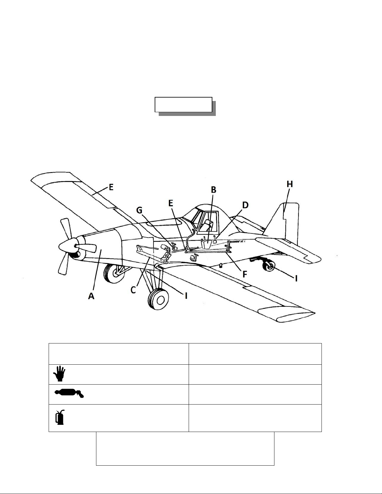
THRUSH AIRCRAFT, INC – MODEL S2R-G10
AIRCRAFT MAINTENANCE MANUAL
LUBRICATION
For the lubrication requirements, refer to Figure 2-4: Lubrication Chart (9 sheets). Before
adding grease to fittings, wipe the fittings clean. Lubricate the fittings and wipe off the excess
lubricant. Lubricate the hinges with a squirt can or a brush moistened wi th oil. Wipe off the
excess oil to prevent accumulation of dirt and grit.
WARNING
THE DRAWINGS OF FIGURE 2-4, SHEETS 1
THRU 9, ARE FOR LUBRICATION REFERENCE
ONLY. THEY DO NOT NECESSARILY SHOW
PROPER ASSEMBLY DETAILS AND ARE NOT
TO BE USED AS ASSEMBLY REFERENCE..
Figure 2-4: Lubrication Chart (Sheet 1 of 9)
APPLICATION SYMBOL
2-30
Page Effective 03/26/2010
HAND PACK
LUBRICATION GUN
OIL CAN
Use only MIL-G-24139 (Aeroshell 6) grease in
* NOTE*
propeller.
SPECIFICATIONS AND TYPE OF
LUBRICANT
MIL-G-81322 (AEROSHELL 22)
AIRCRAFT GREASE
MIL-G-81322 (AEROSHELL 22)
AIRCRAFT GREASE
MIL-L-22851 (AEROSHELL OIL W
15W50) OR EQUIVALENT –
LUBRICATING OIL
Page 48
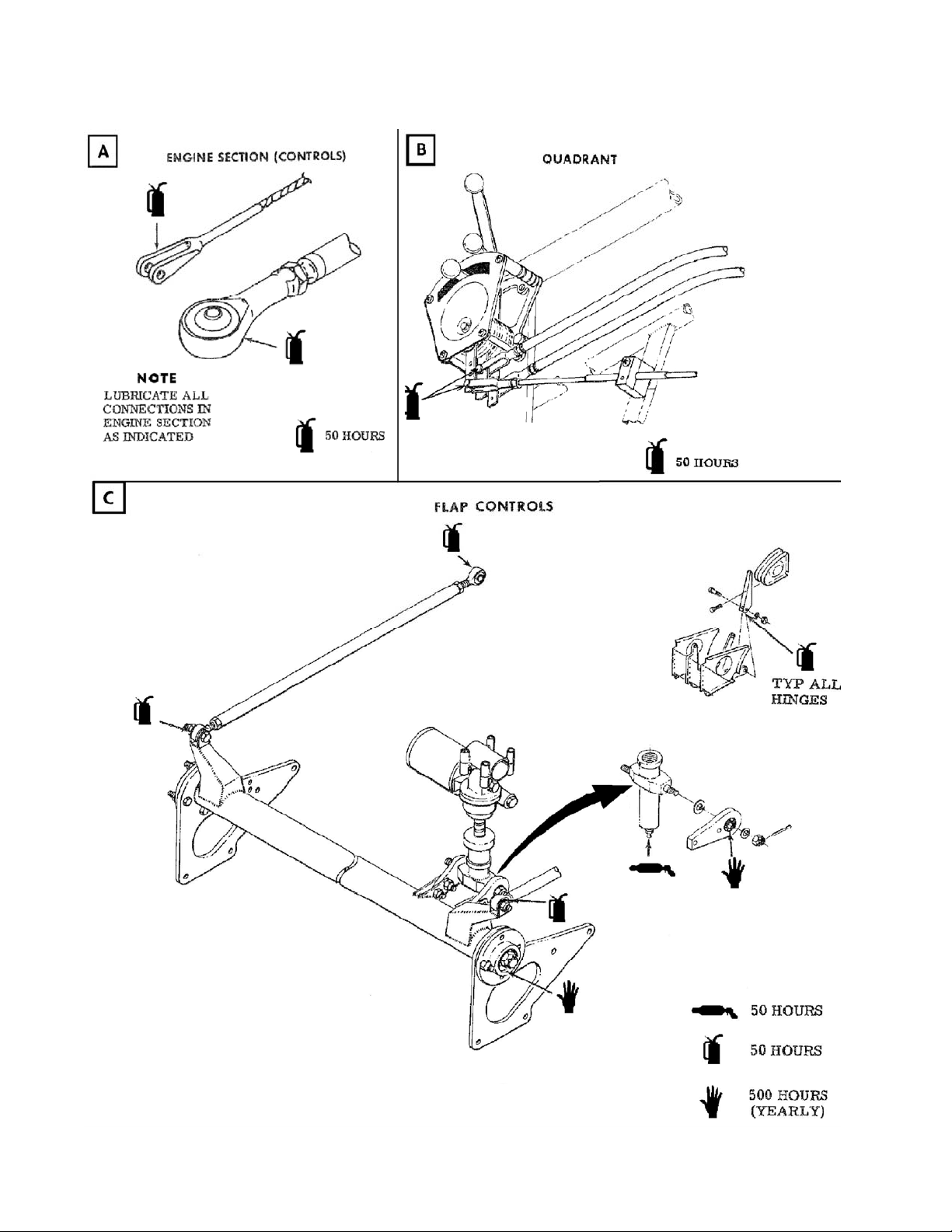
THRUSH AIRCRAFT, INC – MODEL S2R-G10
AIRCRAFT MAINTENANCE MANUAL
Figure 2-4: Lubrication Chart (sht. 2 of 9)
Effective: 03/26/2010 Page 2-31
Page 49
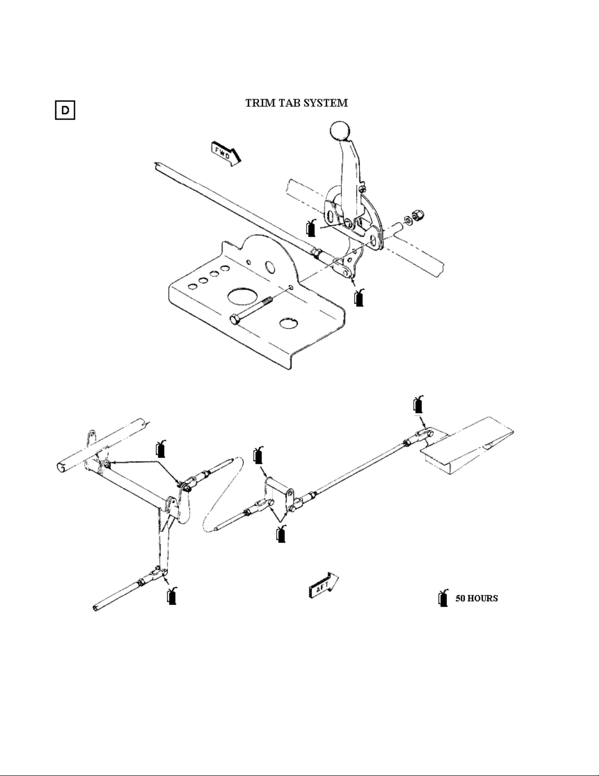
THRUSH AIRCRAFT, INC – MODEL S2R-G10
AIRCRAFT MAINTENANCE MANUAL
Figure 2-4: Lubrication Chart (sht. 3 of 9)
Page Effective 03/26/2010 2-32
Page 50
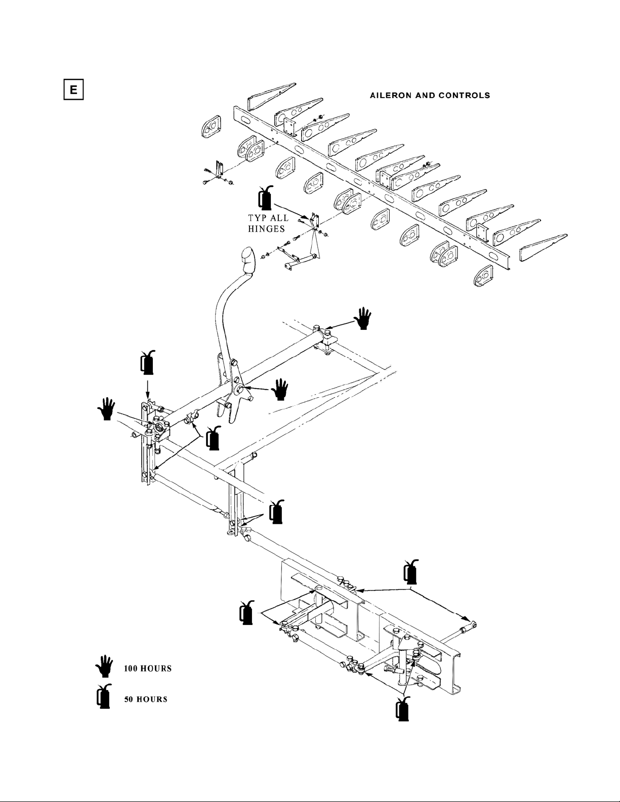
THRUSH AIRCRAFT, INC – MODEL S2R-G10
AIRCRAFT MAINTENANCE MANUAL
Figure 2-4: Lubrication Chart (sht. 4 of 9)
Effective: 03/26/2010 Page 2-33
Page 51
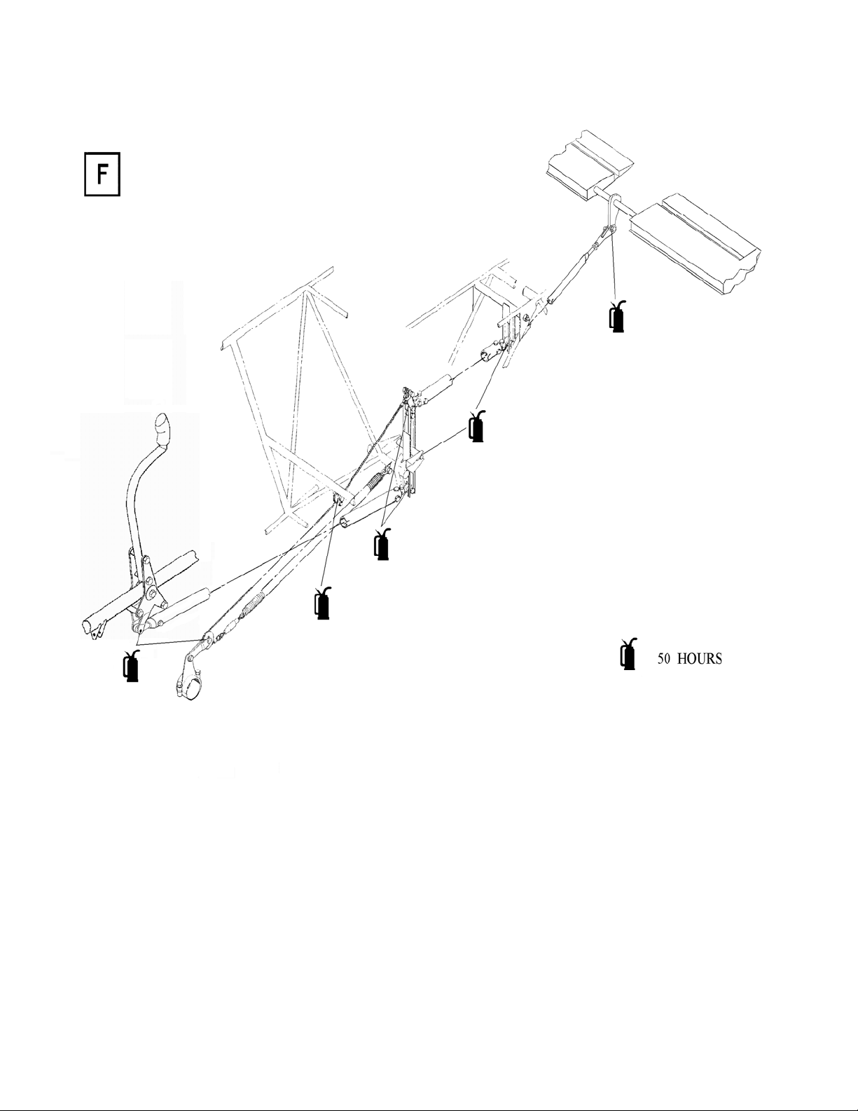
THRUSH AIRCRAFT, INC – MODEL S2R-G10
AIRCRAFT MAINTENANCE MANUAL
Figure 2-4: Lubrication Chart (sht. 5 of 9)
Page Effective 03/26/2010 2-34
Page 52
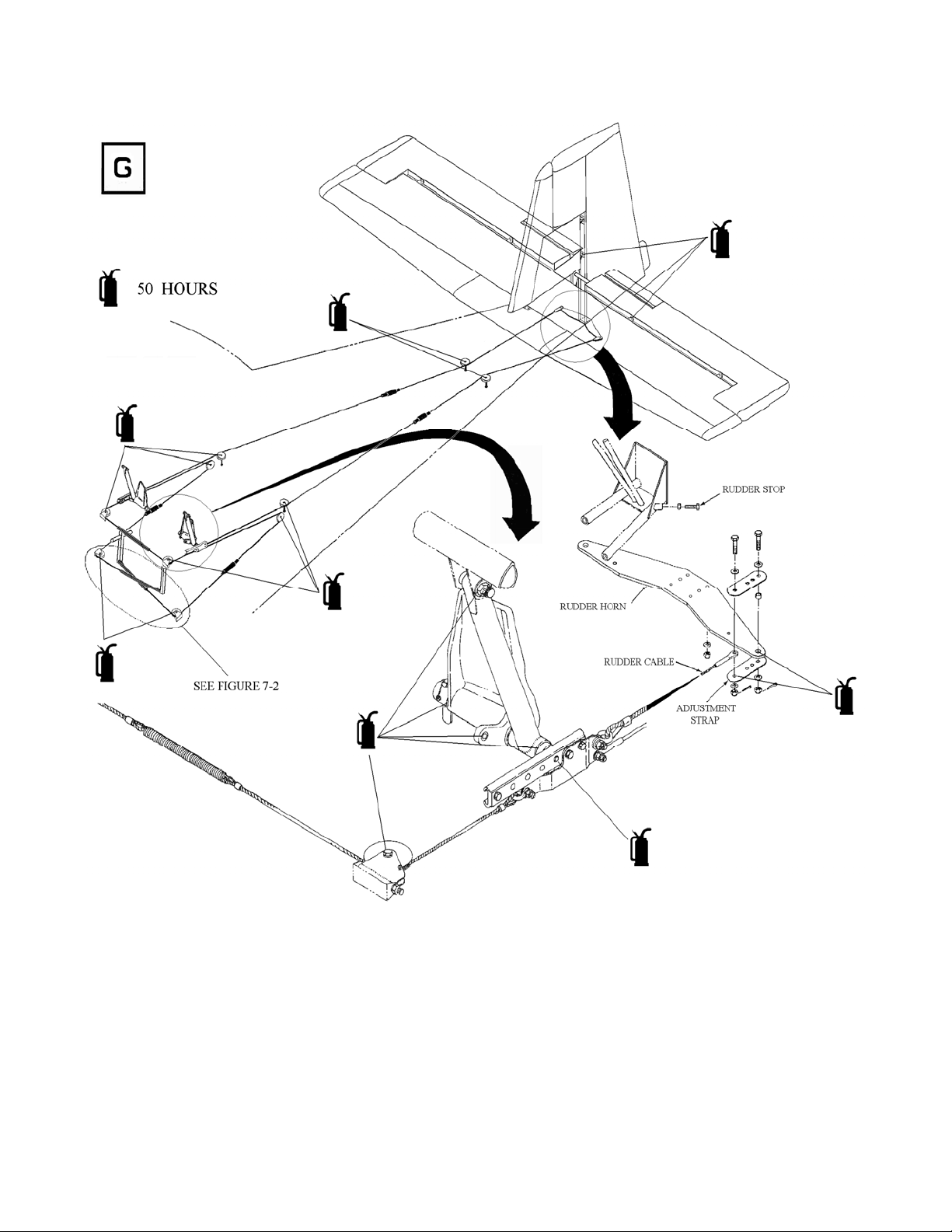
THRUSH AIRCRAFT, INC – MODEL S2R-G10
AIRCRAFT MAINTENANCE MANUAL
Figure 2-4: Lubrication Chart (sht. 6 of 9)
Effective: 03/26/2010 Page 2-35
Page 53
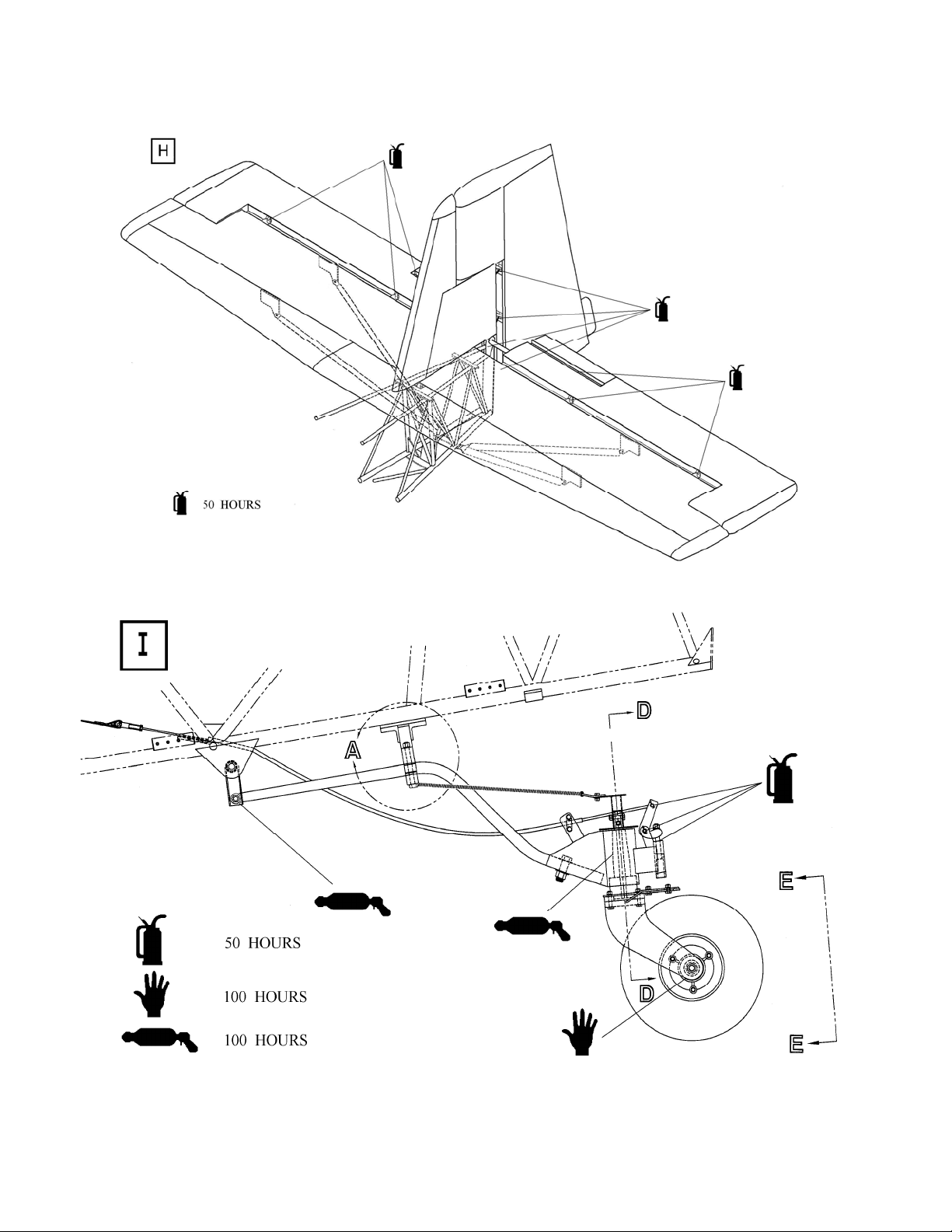
THRUSH AIRCRAFT, INC – MODEL S2R-G10
AIRCRAFT MAINTENANCE MANUAL
Figure 2-4: Lubrication Chart (sht. 7 of 9)
Figure 2-4: Lubrication Chart (sht. 8 of 9)
Page Effective 03/26/2010 2-36
Page 54
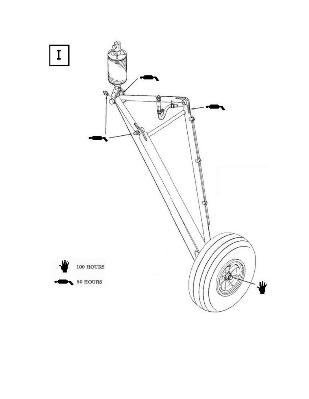
THRUSH AIRCRAFT, INC – MODEL S2R-G10
AIRCRAFT MAINTENANCE MANUAL
Figure 2-4: Lubrication Chart (sht. 9 of 9)
Effective: 03/26/2010 Page 2-37
Page 55

THRUSH AIRCRAFT, INC – MODEL S2R-G10
AIRCRAFT MAINTENANCE MANUAL
THIS PAGE INTENTIONALLY LEFT BLANK
Page 2-38 Effective 03/26/2010
Page 56

THRUSH AIRCRAFT, INC – MODEL S2R-G10
AIRCRAFT MAINTENANCE MANUAL
SECTION 3
HYDRAULICS
TABLE OF CONTENTS
HYDRAULIC SYSTEM..................................................................................... 2
GENERAL DESCRIPTION.......................................................................... 2
MASTER CYLINDER .................................................................................. 2
Figure 3-1: Brake Master Cylinder.......................................................... 2
Figure 3-2: Brake Master Cylinder and Rudder Pedal Installation......... 3
BRAKE SYSTEM BLEEDING .................................................................... 4
Figure 3-3: Hydraulic Brakes.................................................................. 4
Figure 3-4: Main Landing Gear Hydraulics............................................. 5
PARKING BRAKES......................................................................................... 6
3-1 Effective: 03/26/2010 Page
Page 57
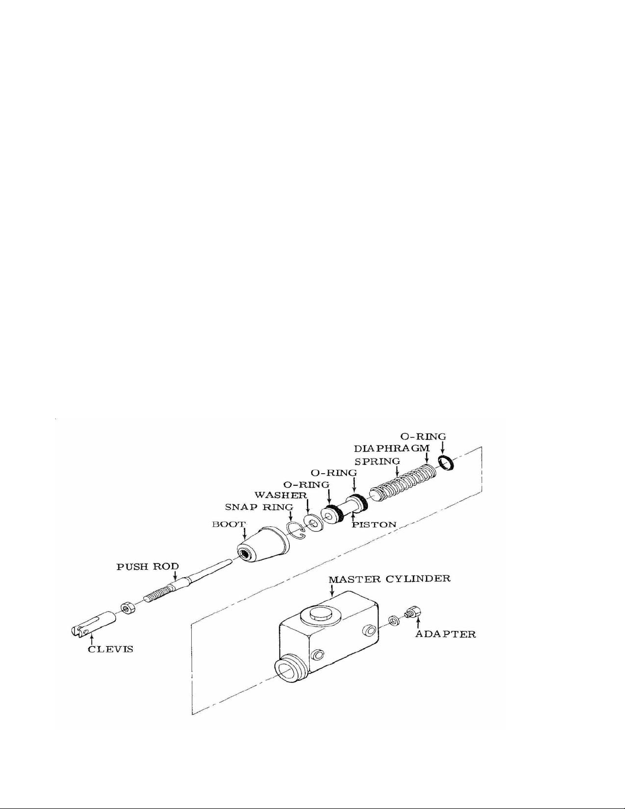
THRUSH AIRCRAFT, INC – MODEL S2R-G10
AIRCRAFT MAINTENANCE MANUAL
HYDRAULIC SYSTEM
GENERAL DESCRIPTION
Ref. Fig. 3-1 thru 3-4
The S2R-G10 aircraft has two individual
hydraulic systems using MIL-H-5606 “red”
hydraulic fluid. Each main landing gear
utilizes a master brake cylinder for the
operation of its brakes and parking brakes.
The master brake cylinder is connected to
dual three-puck disc type brake calipers by
brake lines that are supported by and
clamped to the airframe structure forward
of the master brake cylinder. The
hydraulic brake lines are of rigid steel
tubing, except for the flexible hoses on the
landing gear tripod assembly. The master
brake cylinder is installed aft of the rudderbrake pedals and is actuated by toe
pressure on the pedals. As toe pressure is
applied to the pedals, a push rod and
belcrank linkage moves an actuator rod,
pushing a piston in the master brake
cylinder. This forces hydraulic fluid into the
brake lines and applies pressure to the
appropriate brake. A spring in the master
cylinder returns the piston to its original
position. A check valve allows hydraulic
fluid into the master cylinder if the piston
produces suction on its return stroke.
MASTER CYLINDER
Ref. Fig. 3-1
The brake master cylinders contain the
actuating cylinder and a reservoir for
MIL-H-5606 hydraulic fluid. The seals in
the master cylinder have been changed to
ones compatible with this fluid.
Figure 3-1: Brake Master Cylinder
3-2
Page Effective 03/26/2010
Page 58
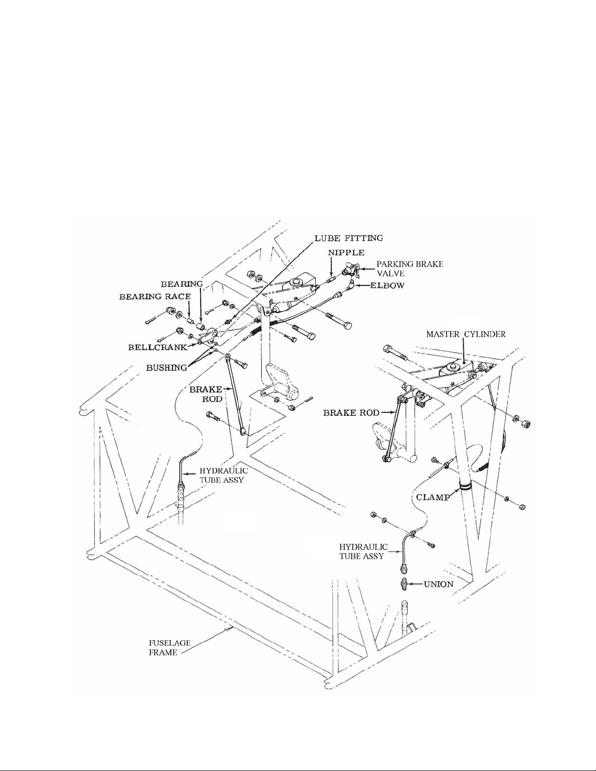
THRUSH AIRCRAFT, INC – MODEL S2R-G10
AIRCRAFT MAINTENANCE MANUAL
The master cylinder piston is actuated by
the push rod, which is in turn actuated by a
mechanical linkage to the rudder pedal
(Ref. Fig. 3-2). Pushing the toe of the
rudder pedal actuates this mechanism,
moves the piston, and thereby forces
hydraulic fluid into the hydraulic line to the
wheel brakes. The piston is returned by a
spring so that hydraulic pressure is
maintained only while the toe brake is
depressed.
Hydraulic fluid reservoirs should be kept at
least half full. If brake “sponginess” is
experienced, check the master cylinder
reservoir first. If it is empty or nearly
empty, it should be filled and the brake
system bled.
The master cylinders also have a lever
which locks the push rod in place to hold
the parking brakes on.
Figure 3-2: Brake Master Cylinder and Rudder Pedal Installation
3-3 Effective: 03/26/2010 Page
Page 59
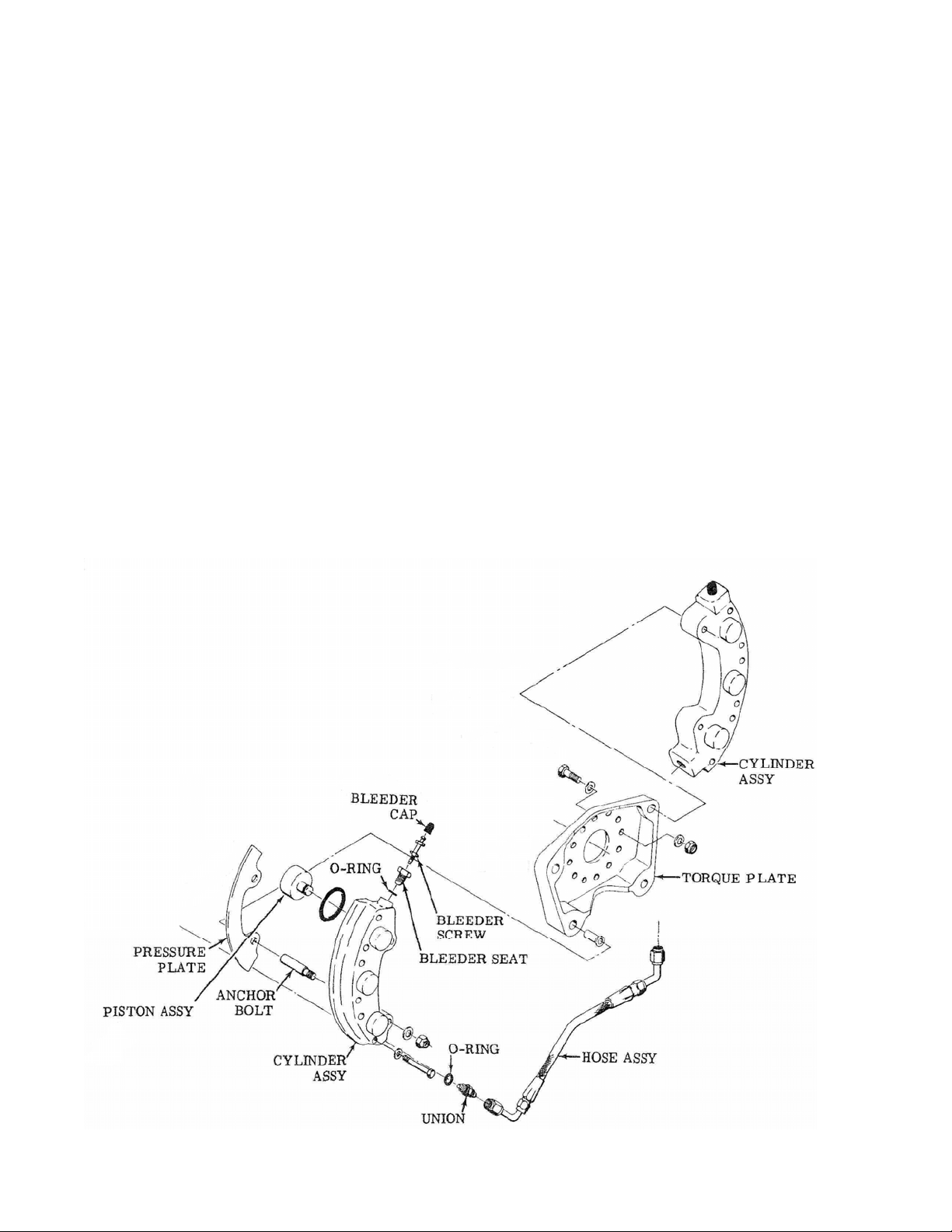
THRUSH AIRCRAFT, INC – MODEL S2R-G10
AIRCRAFT MAINTENANCE MANUAL
BRAKE SYSTEM BLEEDING
Ref. Fig. 3-3
If weak or “spongy” brakes are
experienced, it most likely means that air
has gotten into the hydraulic system for
that side. Air in the brake lines
compresses as the master cylinder is
actuated, allowing less pressure to get to
the brake cylinders.
To eliminate this air the brakes must be
bled, as follows:
1. Ensure that the master cylinder
reservoir is full. Leave the filler cap off.
2. Have available a clean container of at
least a pint capacity, a length of 3/16”
ID clear plastic tubing, clean rags and
extra MIL-H-5606 hydraulic fluid.
3. Put the clear plastic tubing on one of
the bleeder valves at the bottom of the
brake calipers and open the bleeder
valve with a wrench. Direct the
hydraulic fluid into a clean container.
4. Have a helper in the cockpit actuate the
brake pedals slowly through a number
of full strokes, ensuring that the master
cylinder reservoir does not run dry.
Refill the master cylinder reservoir as
necessary.
5. Have the helper continue to operate the
brake pedal until the stream of
hydraulic fluid coming out of the
bleeder valve is completely free of air
bubbles.
Figure 3-3: Hydraulic Brakes
3-4
Page Effective 03/26/2010
Page 60
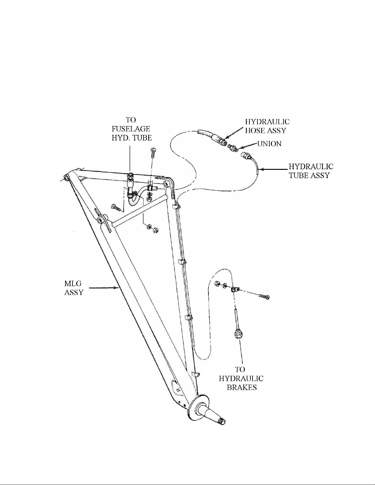
THRUSH AIRCRAFT, INC – MODEL S2R-G10
AIRCRAFT MAINTENANCE MANUAL
6. Close the bleeder valve and place the
plastic tube on the other bleeder valve.
7. Bleed that caliper the same as above.
It should not take more than two brake
pedal strokes.
8. Close that bleeder valve and top off the
master cylinder hydraulic reservoir.
9. Dispose of the hydraulic fluid bled into
the container properly. DO NOT reuse
this hydraulic fluid, as it may be
contaminated.
Figure 3-4: Main Landing Gear Hydraulics
3-5 Effective: 03/26/2010 Page
Page 61

THRUSH AIRCRAFT, INC – MODEL S2R-G10
AIRCRAFT MAINTENANCE MANUAL
An alternative method of bleeding the
brakes is as follows:
1. Place a large clean container under the
master brake cylinder and uncap the
hydraulic fluid reservoir.
2. Bleed the outlet hose of a “pressure
pot” full of MIL-H-5606 “red” hydraulic
fluid until a steady stream of hydraulic
fluid comes out.
3. Place this outlet hose over a bleeder
valve and then open the bleeder valve.
4. Open the press ure pot valve and force
hydraulic fluid through the caliper and
up the brake lines to the master
cylinder.
5. Force at least a pint of hydraulic fluid
through the brake lines into the master
cylinder reservoir, allowing it to
overflow.
6. Close the bleeder valve and connect
the pressure pot line to the other
bleeder valve.
7. Open the bleeder valve and force
another few fluid ounces of hydraulic
fluid back to the master cylinder.
8. Close the bleeder valve and clean off
the brake master cylinder and dispose
of the flushed hydraulic fluid properly.
Be sure to replace the reservoir cap
before releasing the airplane.
PARKING BRAKES
Ref. Fig. 3-2
Parking brakes are actuated by depressing
the brake pedals as normal and then
locking the pressure in the brake system
downstream of the master cylinders.
Parking brakes are only for temporary
parking. Any leaks or seepage of
hydraulic fluid from the brake system or
slippage of the master cylinder plunger will
slowly release the parking brake. If the
airplane is being parked for more than 4
hours it should be tied down.
Operate the individual parking brakes as
follows:
ON – Depress rudder pedal, pull parking
valve lever, take pressure off of rudder
pedal.
OFF – Depress rudder pedal, valve will
deactivate and lever will pop in.
3-6
Page Effective 03/26/2010
Page 62

THRUSH AIRCRAFT INC - MODEL S2R-G10
AIRPLANE MAINTENANCE MANUAL
SECTION 4
POWER PLANT AND PROPELLER
TABLE OF CONTENTS
POWER PLANT................................................................................................................... 2
AIR CLEANING SYSTEM ....................................................................................................................................2
ENGINE BUILDUP...............................................................................................................................................2
OIL CONTAMINATION ........................................................................................................................................2
ENGINE REMOVAL.............................................................................................................................................2
ENGINE INSTALLATION.....................................................................................................................................3
PROPELLER........................................................................................................................ 4
PROPELLER DESCRIPTION AND OPERATION................................................................................................5
PROPELLER REMOVAL – ..................................................................................................................................5
MCCAULEY ............................................................................................................................................................5
PROPELLER INSTALLATION – MCCAULEY ........................................................................................................6
PROPELLER ADJUSTMENTS – MCCAULEY –REF. FIG. 4-1................................................................................6
Figure 4-1: Propeller Specifications .............................................................................. 7
SPINNER INSTALLATION – MCCAULEY – REF. FIG. 4-2......................................................................................8
Figure 4-2:.....................................................................................................................8
PROPELLER REMOVAL – ..................................................................................................................................8
HARTZELL..............................................................................................................................................................8
PROPELLER INSTALLATION – HARTZELL..........................................................................................................9
HARTZELL ADJUSTMENTS ...............................................................................................................................9
SPINNER INSTALLATION – HARTZELL..............................................................................................................11
PROPELLER BALANCING................................................................................................................................11
RIGGING AIRFRAME ENGINE CONTROLS..................................................................... 11
RIGGING INSTRUCTIONS................................................................................................................................12
RIGGING FUEL CUTOFF AND FEATHER................................................................. 13
THROTTLE RIGGING:................................................................................................ 14
SPEED LEVER RIGGING:.......................................................................................... 15
ENGINE RIGGING CHECKS AND ADJUSTMENTS.........................................................................................15
GROUND IDLE ADJUSTMENTS:............................................................................... 16
EMERGENCY CUT OFF AND PROPELLER FEATHER CHECK .............................. 16
THE TORQUE SYSTEM.................................................................................................... 16
DESCRIPTION AND OPERATION....................................................................................................................16
CALIBRATION OF TORQUE INDICATING SYSTEM................................................. 16
Figure 4-7: Ground Idle Adjustment............................................................................ 17
Effective: 03/26/2010 Page 4-1
Page 63
THRUSH AIRCRAFT INC - MODEL S2R-G10
AIRPLANE MAINTENANCE MANUAL
POWER PLANT
The Garrett TPE-331 powered Turbo
Thrush is lighter and more streamlined
than the radial engine powered versions.
This results in substantially improved
aircraft performance.
AIR CLEANING SYSTEM
The Garrett TPE-331 engine does not
incorporate an air filtration system, as do
the corresponding Pratt & Whitney engines
used on this aircraft. No air filtration is
required on the TPE-331 engine.
A 6061T6 ¼” Aluminum Grille, located at
the entrance of the compressor inlet,
prevents engine ingestion of objects such
as large birds.
ENGINE BUILDUP
CAUTION
Consult the Honeywell engine
maintenance manual before
removing the new engine from
the shipping container.
Engine build-up consists of installing a
restricted (snubber) oil pressure fitting, a
restricted (snubber) fuel pressure fitting,
rigging the engine’s power management
system, moving the fuel shut off valve aft
of the compressor flange, moving the NTS
lockout solenoid, installing the tachometer
generator and installing the NTS and Beta
pressure switches. If installing a fuel flow
transducer, do so at this time IAW the
applicable section of this manual.
OIL CONTAMINATION
If the engine is being removed because of
oil contamination or if there is possibility of
oil contamination, scrap the oil cooler and
thoroughly wash out the inside of all oil
carrying lines and hoses or replace them.
Return the propeller and any other oil
wetted components to the rated
maintenance facility for disassembly and
cleaning. Failure to comply with the above
procedure will prove to be false economy,
as the new engine will be contaminated by
old impurities.
* NOTE *
Tag or identify all hoses, bolts, nuts,
and electrical connector plugs and
note harness clamp locations for
installation on the new engine. Cap
all open hoses and engine ports to
prevent contamination.
ENGINE REMOVAL
CAUTION
To prevent dam
mechanisms, if the engine is to
be idle more than the time
recommended by the engine
manufacturer, it should be
preserved in accordance with
the engine manufacturer’s
recommendations, as outlined
in the engine maintenance
manual.
a. Preliminary steps:
1. Turn the fuel selector valve off and
drain engine oil.
2. Disconnect electrical power to the
aircraft.
3. Provide suitable containers under
the engine to catch fuel and oil
spillage.
b. Remove engine cowling.
c. Disconnect batteries.
d. Remove propeller IAW the
manufacturer’s instructions or the
appropriate section of this manual.
e. Remove exhaust nozzle.
f. Disconnect the following tube and hose
assemblies at the locations noted:
age to internal
4-2
Page Effective: 03/26/2010
Page 64
THRUSH AIRCRAFT INC - MODEL S2R-G10
AIRPLANE MAINTENANCE MANUAL
* NOTE *
Tag and identify all tube and hose
assemblies to facilitate and ensure
correct installation of the engine.
Cap and plug all openings to
prevent contamination.
1. Oil cooler lines – Front nose case
and oil tank.
2. All drain lines which are routed to
the left hand shin skin.
3. Oil pressure line.
4. Torque pressure and vent lines.
5. Fuel pressure and fuel supply
hose.
6. Fuel manifold purge system hose.
7. Unfeathering pump hoses.
8. Oil breather tube and hose
assembly.
g. Disconnect the electrical leads and
connector plugs at the locations noted.
1. EGT compensator
2. Oil vent
3. Oil temp
4. NTS lock out valve
5. Primaries only valve
6. Beta pressure switch
7. NTS pressure switch
* NOTE *
It is not necessary to remove
engine control belcrank assembly
from engine mount for engine
removal.
i. Remove the engine from the aircraft as
follows:
1. Attach the engine sling to the
propeller shaft face or to a fixture
in place of the top engine mount.
2. Connect a suitable hoist to the
engine sling
3. Rem ove cotter pins and nuts from
engine supporting bolts.
4. With the hoist supporting the
engine’s weight, push the
supporting bolts out.
CAUTION
Before hoisting the engine
unit clear of the fuselage nose
section, check that all wiring,
cables, tube and hose
assemblies are disconnected
and free from snags.
5. Hoist the engine unit clear of the
fuselage nose section and install
in a suitable stand. Remove the
engine sling.
8. Tachometer generator
9. Chip Detector
10. Fuel Valve
11. Ignition exciter box
12. Starter/generator
13. Engine ground wire
14. Fuel flow transducer
15. (optional equipment)
h. Disconnect the engine control linkages
from engine.
Effective: 03/26/2010 Page
4-3
a. Install the engine in the aircraft as
ENGINE INSTALLATION
follows:
1. Attach the engine sling to the
propeller shaft flange or to a
fixture in place of the top engine
mount.
2. Remove the engine from the
stand and carefully position in the
engine mount.
3. Align the bolt holes of the engine
vibration mounts with those of the
Page 65

THRUSH AIRCRAFT INC - MODEL S2R-G10
AIRPLANE MAINTENANCE MANUAL
mounts. Install the attaching
hardware. Torque the three
forward bolts to 480-600 inchpounds and the rear bolt at 25
inch-pounds. Install all cotter
pins.
Forward engine isolators: P/N
93438-06 (Torque 4ea. NAS147DH bolts, to attach isolator body to
engine 450±65 in. lbs.)
Rear engine isolators: P/N
93395-06 (Torque upper AN363C820 nut 550-650 in. lbs., AN17630 or NAS1106-35D hinge bolt
with AN310-6 nut 25 in. lbs.)
b. Connect the following tube and hose
assemblies:
1. Oil cooler lines – Front hose case
and oil tank.
2. All drain lines.
3. Oil pressure hose.
4. Torque pressure and vent hose.
5. Fuel pressure
6. Fuel purge.
10. Fuel valve
11. Ignition exciter box
12. Starter/generator
13. Engine ground wire
14. Fuel flow transducer (optional
equipment)
d. Rig the engine controls in accordance
with applicable Honeywell Maintena nce
Manual.
e. Rig all airframe control linkages in
accordance with subsequent
paragraphs of this section.
f. Install the propeller.
g. If the engine has been preserved for
long term storage, refer to the
Honeywell Engine Maintenance
Manual for the proper procedures to
flush and clean for installation.
h. Service the engine oil.
i. Perform the engine ground test and
checks. Note: Refer to procedures
outlined later in this section and
TPE331-10 Maintenance Manual.
7. Unfeathering pump plumbing.
8. Oil breather tube and hose
assembly.
c. Connect the electrical leads and
connector plugs at the following
locations.
1. EGT compensator
2. Oil vent
3. Oil temp
4. NTS lock out valve
5. Primaries only valve
6. Beta switch
7. NTS switch
8. Tachometer generator
9. Chip detector
CAUTION
Prior to engine run, ensure that
the air inlet is clear of foreign
material.
j. Ensure that there are no fuel or oil
leaks.
PROPELLER
Two propeller manufacturers’ products are
utilized on the TPE331-10 powered Turbo
Thrush. The TPE331-10 engine uses the
McCauley four-bladed propeller with
internal start locks or the Hartzell fourbladed propeller with external start locks.
All propellers are constant speed, fullfeathering, reversible type propellers which
operate in the manner described in the
following description.
4-4
Page Effective: 03/26/2010
Page 66

THRUSH AIRCRAFT INC - MODEL S2R-G10
AIRPLANE MAINTENANCE MANUAL
PROPELLER DESCRIPTION AND
OPERATION
The propeller is a single-acting unit in
which hydraulic pressure opposes the
forces of springs and counterweights to
obtain the correct pitch for engine load.
Hydraulic pressure urges blades toward
low pitch (increasing rpm), while springs
and counterweights urge blades toward
high pitch (decreasing rpm). See the
propeller owner’s manual for more explicit
details.
The source of hydraulic pressure for
operation is oil from the engine lubricating
system, boosted in pressure by the
governor gear pump, and supplied to the
propeller piston through the beta tube
(beta tube supplied by engine
manufacturer). The flow of oil through the
governor and the propeller does not
interfere with engine lubrication.
The propeller is designed to operate in two
modes of operation – governor mode and
beta mode.
Governor mode
from the propeller (by the governor control
valve as positioned by flyweights),
increasing and decreasing blade angle
(changing pitch) as required when the
propeller speed control setting is altered,
or to control and stabilize engine speed
with varying power conditions or flight
altitudes with a fixed speed setting.
. Oil is metered to and
speed operation, starting, stopping and
ground run-up is consistent with standard
practice for this type propeller.
In-flight loss of oil pressure, whether due to
system failure or pilot manipulation of the
feather control, will cause the blades to
move to the feathered position. The
electric, hydraulic, unfeathering pump is
required to un-feather the propeller.
The propeller hub cavity is partially filled
with turbine oil which is sealed in the hub
and isolated from engine oil. This oil
provides lubrication and corrosion
protection to blade bearings and other
internal parts.
The propeller is equipped with a start lock
mechanism which prevents the blades
from going to full feather on engine shutdown. The mechanism operates in
response to the centrifugal force acting on
rotating weights. The mechanism is
designed to engage a fixed stop and limit
piston movement in the direction of
increasing blade angle during engine shutdown. During all flight operations, the
weights are in a disengaged position and
offer no resistance to feathering,
Unfeathering or reversing of the propeller.
PROPELLER REMOVAL –
McCauley
Remove upper half of nose bowl.
Beta mode. The pilot may select beta
mode for ground reversing or taxi
operation. In the beta mode, the
aircraft/engine mechanical linkage
repositions a sleeve on the beta tube to
allow high pressure oil to reach the
propeller piston and move the blades
toward reverse pitch. In beta mode the
engine automatically, by controlling fuel
flow, develops power output to correspond
with the pitch setting (determined by the
pilot).
Cockpit procedure for normal constant
Effective: 03/26/2010 Page
Remove spinner and spinner fillets. Mark
location of parts. (Note number of shims
under the plastic spinner support.)
Remove beta tube retainer plug assembly
and beta tube.
* NOTE *
Beta tube retainer plug cannot be
removed with McCauley propeller in
feathered position. Remove plug
assembly with propeller on start
locks.
* NOTE *
4-5
Page 67
THRUSH AIRCRAFT INC - MODEL S2R-G10
AIRPLANE MAINTENANCE MANUAL
Mark propeller hub flange and the
engine shaft flange so that the
propeller can be reinstalled in its
original position. This will prevent
disturbing the propeller/engine
combination dynamic balancing if
the same propeller is to be
reinstalled.
Remove propeller retaining nuts and
bushings.
Using a proper hoist and straps to support
propeller, remove propeller and discard
propeller shaft O-ring.
PROPELLER INSTALLATION –
McCauley
Lube O-ring with clean engine oil and
install on propeller shaft.
CAUTION
Ensure that the propeller shaft
dam has been removed. The
dam can be removed using
Garrett puller P/N 285397-1-1 or
equivalent. The McCauley
propeller will not function
properly with the dam installed.
Install propeller (either feathered or on
start locks) in accordance with the
applicable propeller owner’s manual or
maintenance manual.
Lube beta tube with clean turbine engine
oil and insert into propeller shaft. Screw
tube in 35 turns. Do not lock at this time
as fine adjustment will be done later.
PROPELLER ADJUSTMENTS –
McCauley –Ref. Fig. 4-1
Accomplish propeller checks and
adjustments only when the aircraft engine
controls have been fully rigged to their
correct positions, the prop blade is parallel
with the horizon and the aircraft wings are
generally level. Zero the propeller
protractor on the propeller hub and take all
measurements at the blade station given in
the propeller owner’s manual, or Figure 4-
1.
The flight idle and reverse blade angle is
measured with the unfeathering pump
supplying steady oil pressure to the
propeller.
* NOTE *
The unfeathering pump draws oil
from the engine oil tank to actuate
the propeller. Bleed oil from the
prop is dumped into the reduction
gear box, not the engine oil tank. If
the unfeathering pump is operated
frequently or for prolonged periods,
it will pump the engine tank dry. If
you hear the pump suddenly
unload, cavitate or speed up, stop
the pump. You can pump the oil
out of the gearbox and back into the
oil tank by turning the propeller 50
revolutions by hand or by the
starter. It is not uncommon to
experience some oil loss overboard
from the vent.
WARNING
DO NOT USE THE STARTER TO
RETURN OIL TO THE ENGINE
TANK IF THE PROPELLER IS IN
THE FEATHERED
TURN THE PROPELLER BY
HAND ONLY IN THE NORMAL
DIRECTION OF ROTATION.
The feathered, start lock and reverse blade
angles are preset by the propeller
manufacturer. The flight idle blade angle is
hydraulically controlled by the position of
the beta tube. Remove the locking pin
(McCauley P/N B4795) before attempting
to turn the beta tube. Turning the beta
tube clockwise (looking aft) will decrease
the blade angle. Counterclockwise
movement will increase the blade angle.
POSITION.
Page 4-6 Effective: 03/26/2010
Page 68

THRUSH AIRCRAFT INC - MODEL S2R-G10
AIRPLANE MAINTENANCE MANUAL
PROPELLER
Model Number
Used On Engine Type TPE331-10 TPE331-10 TPE331-10
Diameter (inches) max. 109.5 106.0 108.0
Diameter (inches) min. 107.5 105.0 105.0
Measurement Station
(inches)
Start Lock Blade Angle
(degrees)
Flight Idle Blade Angle
(degrees)
Feathered Angle (degrees) 81.2±0.5 87.4±0.2 87.4±0.2
Reverse Angle (degrees) -6.0±0.5 -4.0±0.2 -4.0±0.2
Hartzell 4-
blade
HCB4TN-5NL-
LT10890N
42 30 30
-1.4±0.1 6.0±0.2 6.0±0.2
4.5±0.2 12.0±0.5 12.0±0.5
McCauley 4-
blade
4HFR34C653-[X]
[X]-L106FA-0
McCauley 4-
blade
4HFR34C662-[X]
[X]-L108FA-0
Figure 4-1: Propeller Specifications
* NOTE *
The beta tube lock cannot be
removed from the propeller in the
feathered position. Do this from the
start lock position.
Checking and adjusting the flight idle blade
angle requires taking the blades off the
start locks to the feathered position. To
accomplish this, move the power lever to
the full reverse position and turn on the
feathering pump to move the blades off the
start locks. Insert McCauley tool P/N
B5021 (Figure 4-2) into the four holes of
the propeller hub. Turn off the
unfeathering pump and pull the emergency
cutoff lever. The blades will move under
spring pressure to the feather position.
Remove the P/N B5021 tool. As an
alternate method, or, if hot engine is
required, start the engine in accordance
with normal start procedures. When ready
to shut down the engine, briefly pull the
power lever into reverse to release the
start locks and return to ground or flight
idle. Actuate the fuel shutoff switch with
the power lever in ground idle or flight idle.
The blades will feather under spring
pressure as the oil pressure decreases.
With the propeller protractor previously
zeroed in the propeller hub and with the
prop in the feathered position, move to the
face of the blade to be measured. Be sure
that the power lever is in the flight idle
position and the prop pitch servo valve is
pinned at 40º with a 1/8” diameter drill bit
or rigging pin. Verify the proper feathered
angle at this time.
If the propeller installation is new or if the
beta tube has been removed or disturbed,
install the beta tube into the housing.
Effective: 03/26/2010 Page 4-7
Page 69
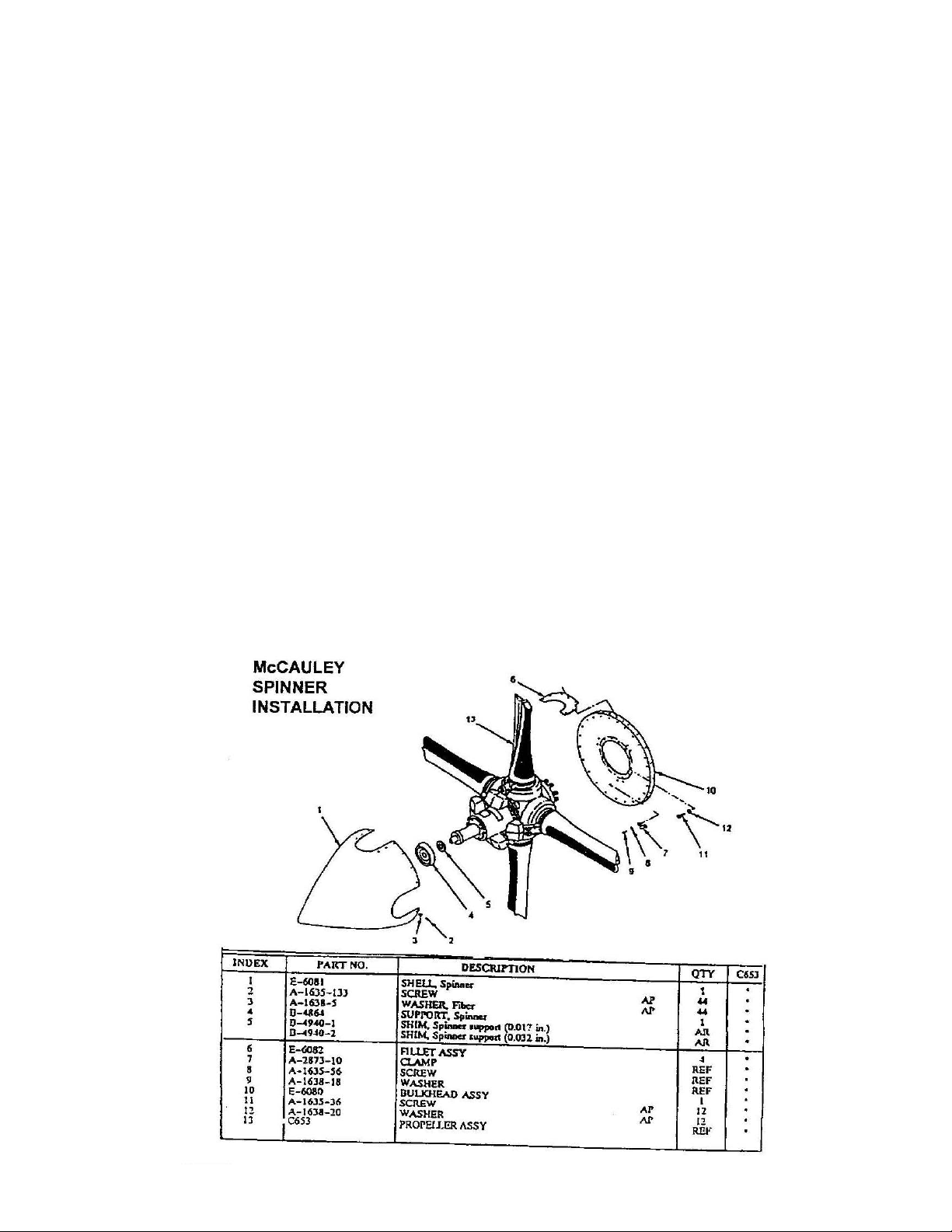
THRUSH AIRCRAFT INC - MODEL S2R-G10
AIRPLANE MAINTENANCE MANUAL
Count the turns, beginning with the first
thread engages. 35 full turns is equivalent
to approximately 12 degrees of flight idle
blade angle.
Have an assistant turn on the unfeathering
pump. When the blades move off the
feathered stop into the flight idle angle,
check blade angle at the proper blade
station. Adjust the beta tube accordingly to
achieve 12 º ±1/2 º blade angles on a hot
engine. If the engine is cold, the cold
setting will be about 1º lower. For
example, if 12º is required, set a cold
engine at 11º. Check the blade again after
the engine has been run and is still hot.
SPINNER INSTALLATION –
McCauley – Ref. Fig. 4-2
After all adjustments and ground runs are
completed, install spinner as follows:
McCauley requires installation of four fillets
prior to spinner. The spinner is installed
I.A.W. decal on bulkhead and/or McCauley
Service Letter 1991-11A, which states:
Install shims and spinner support on
propeller cylinder. Lightly press shell snug
against support and check alignment of
holes in shell with holes in bulkhead.
Adjust number of shims until holes are
approximately 3/64 inch from being in true
alignment. Push hard in shell until holes
are aligned. A sufficient number of shims
should be used which permits just enough
alignment from screw installation while
pushing hard against shell. Install four
screws and washers equally spaced.
Relax force and install remaining screws
and washers.
PROPELLER REMOVAL –
Hartzell
a. Remove upper nose bowl.
b. Remove spinner (mark location).
c. Remove beta tube lock bolt and beta
tube.
Figure 4-2:
4-8
Page Effective: 03/26/2010
Page 70

THRUSH AIRCRAFT INC - MODEL S2R-G10
AIRPLANE MAINTENANCE MANUAL
* NOTE *
Mark propeller hub flange and the
engine shaft flange so that the
propeller can be reinstalled in its
original position. This will prevent
disturbing the propeller/engine
combination dynamic balancing if
the same propeller is to be
reinstalled.
d. Remove the safety wire from the
propeller mounting bolts. Using a box
head wrench, remove the eight bolts
securing the propeller in place and with
a suitable crane hoist and sling,
remove the propeller from the airplane.
PROPELLER INSTALLATION –
Hartzell
a. With a suitable crane hoist and sling,
carefully move the propeller assembly
to the aircraft engine mounting flange.
b. Make sure engine flange and propeller
flange are clean and free of burrs.
c. Place new P/N C-3317-230 “O” ring on
engine flange.
d. Install the propeller on the engine by
inserting the two dowel pins on the
propeller flange in the appropriate
holes on the propeller shaft flange.
*NOTE*
The propeller will fit on the
engine in two positions, 180º
apart from each other. Either
position is permissible to use.
If the same propeller is being
reinstalled, install in the
original position as previously
marked. This will prevent
disturbing the propeller/
engine combination dynamic
balancing.
e. After assuring that complete and true
surface contact between the flanges
has been established, apply (MILPRE-83483, Hartzell P/N A-3338-1 or
latest upgrade) antiseize compound to
mounting bolt threads and washer
surfaces (and remainder of bolts if
desired). For the HC-B4TN-5NL
propeller install eight (8) P/N B-3339
bolts and eight (8) A-2048-2 washers
through engine flange into the
propeller flange.
WARNING
CHAMFER OF WASHER
MUST FACE BOLT HEAD ON
INSTALLATION.
f. Using (Hartzell P/N AST-2877) special
torque adapter and a standard torque
wrench, torque all eight bolts
according to instructions as outlined in
the latest edition of Hartzell Propeller
Inc. Owner’s Manual and Log Book
No. 139 to a final torque of 100-105 ft.
lbs. wet (1200-1260 in. lbs. wet.).
g. Safety all mounting bolts in an
airworthy manner with .032” (0.81 mm)
minimum diameter stainless steel
safety wire. (Two bolts per safety).
h. Procedure for reinstallation of piston
“dome” nut (if applicable).
1. Following the installation of the
propeller to engine, use a breaker
bar and a one-inch deep well socket
to hold the pitch change rod.
2. Using a 1 13/16-inch crowfoot
wrench standard torque wrench,
torque the A-880-2 piston nut to
120-ft. lbs. (1440-in. lbs.).
i. Install beta tube (P/N 866533-3) lubed
with engine oil. Screw into the
housing approximately .25 inch. Do
install lock bolt at this time. (See
Propeller Adjustments in this section
for pertinent details).
HARTZELL ADJUSTMENTS
Perform propeller checks and adjustments
only after the aircraft engine controls have
been fully rigged to their correct positions,
Effective: 03/26/2010 Page
4-9
Page 71

THRUSH AIRCRAFT INC - MODEL S2R-G10
AIRPLANE MAINTENANCE MANUAL
the prop blade is parallel with the horizon
and the aircraft wings are generally level.
Zero the propeller protractor on the
propeller hub and take all measurements
at the blade station called out in the
propeller owner’s manual, or Figure 4-1.
Measure the flight idle and reverse blade
angles with the unfeathering pump
supplying steady oil pressure to the
propeller.
* NOTE *
The unfeathering pump draws oil
from the engine oil tank to actuate
the propeller. Bleed oil from the
prop is dumped into the reduction
gear box, not the engine oil tank. If
the unfeathering pump is operated
frequently or for prolonged periods,
it will pump the engine tank dry. If
you hear the pump suddenly
unload, cavitate or speed up, stop
the pump. You can pump the oil
out of the gearbox and back into the
oil tank by turning the propeller 50
revolutions by hand or by the
starter. It is not uncommon to
experience some oil loss overboard
from the vent.
WARNING
DO NOT USE THE STARTER TO
RETURN OIL TO THE ENGINE
TANK IF THE PROPELLER IS IN
THE FEATHERED POSITION.
TURN THE PROPELLER BY
HAND ONLY
DIRECTION OF ROTATION.
The feathered, start lock and reverse blade
angles are preset by the propeller
manufacturer. The flight idle blade angle is
hydraulically controlled by the position of
the beta tube. Remove the locking bolt
and nut before attempting to turn the beta
tube. Turning the beta tube clockwise
(looking aft) will decrease the blade angle.
Counterclockwise movement will increase
IN THE NORMAL
the blade angle.
Checking and adjusting the flight idle blade
angle requires taking the blades off the
start locks to the feathered position. To
accomplish this, move the power lever to
the full reverse position and turn on the
feathering pump to move the blades off the
start locks. Retract the start locks with
your fingers and hole them in place with
modified clothespins. Turn off the
unfeathering pump and pull the emergency
cutoff lever. The blades will move under
spring pressure to the feather position. As
an alternate method, or, if hot engine is
required, start the engine in accordance
with normal start procedures. When ready
to shut down the engine, briefly pull the
power lever into reverse to release the
start locks and return to ground or flight
idle. Actuate the fuel shutoff switch with
the power lever in ground idle or flight idle.
The blades will feather under spring
pressure as the oil pressure decreases.
With the propeller protractor previously
zeroed on the propeller hub and with the
prop in the feathered position, move to the
face of the blade to be measured. Be sure
that the power lever is in the flight idle
position and the prop pitch servo valve is
pinned at 40º with a 1/8” diameter drill bit
or rigging pin. Verify the proper feathered
angle at this time.
If the propeller installation is new or if the
beta tube has been removed or disturbed,
screw the beta tube into the prop until it is
¼ inch inside its housing.
Have an assistant turn on the unfeathering
pump. When the blades move off the
feathered stop to the flight idle angle,
check the blade angle at the proper blade
station. Adjust the beta tube accordingly to
achieve 4.5 degrees plus or minus 0.2
degrees blade angle on a hot engine. If
the engine is cold, the cold setting will be
about 1 degree lower. For example, if 4.5
degrees is required, set a cold engine at
3.5 degrees. Check the blade angle again
4-10
Page Effective: 03/26/2010
Page 72
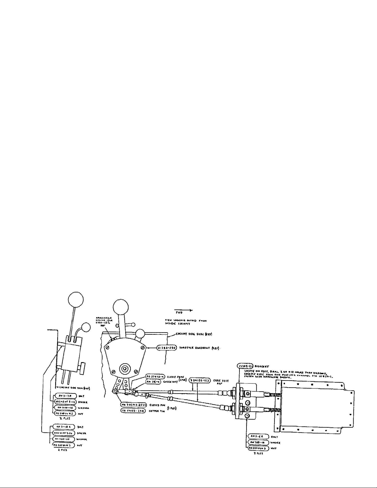
THRUSH AIRCRAFT INC - MODEL S2R-G10
AIRPLANE MAINTENANCE MANUAL
after the engine has been run and is still
hot.
SPINNER INSTALLATION –
Hartzell
Install spinner, aligning marks if replacing
on the same propeller bulkhead. Align
screw holes and install screws (P/N
AN526C1032-8R) with fiber washers P/N
A1020.
PROPELLER BALANCING
Thrush Aircraft, Inc. recommends that the
propeller by dynamically balanced to the
engine whenever a new propeller or an
overhauled propeller is installed, or any
time there is a question of the propeller’s
balance. Following the instruction of the
propeller balancing equipment (Chadwick
Helmuth Vibrex or equivalent equipment),
set the amplitude of vibration given in IPS
(inches per second) on the balancers
meter to a level of .2 or less at 1,500 rpm
Np by adding weights to the light blade(s)
or spinner bulkhead in accordance with
Hartzell Propeller Owners manual P/N 139
chapter 6.
RIGGING AIRFRAME ENGINE
CONTROLS
Engine speed and propeller function is
controlled through connecting rod
assemblies, belcrank assemblies, cables
and cockpit quadrant levers.
This section will explain the procedures for
rigging the TPE 331-10 engine to the
Turbo Thrush airframe engine controls.
This procedure is presented as a general
guide and variation from this procedure is
permitted. Any available adjustment may
be utilized to achieve engine to cockpit
rigging, provided that no thread witness
holes are ported, that lever travel cushion
exists where required, and engine inputs
move from stop to stop.
* NOTE *
Do not add more than four (4)
balance weights (P/N A-1305) in
any one stack. A maximum total of
eight (8) weights are allowed on any
one clamp half.
Figure 4-3:
Effective: 03/26/2010 Page 4-11
Page 73
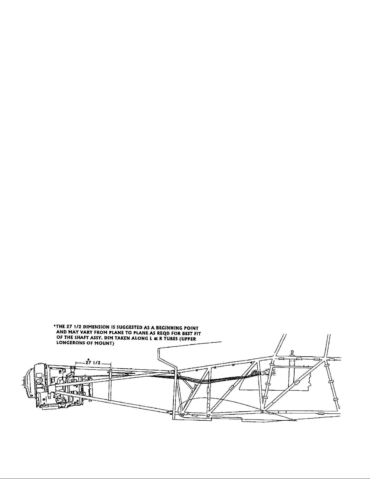
THRUSH AIRCRAFT INC - MODEL S2R-G10
AIRPLANE MAINTENANCE MANUAL
RIGGING INSTRUCTIONS
a. Rigging the throttle quadrant to the
control cables: Ref. Fig. 4-3
1. With clevis forks (2 places) not yet
connected to levers, turn the
AN315-4 check nut in to bottom
out on the cable-end threads.
2. Screw the clevis fork out until the
witness holes is just covered
enough to prevent passage of
.032 diameter safety wire.
3. Count the number of threads
exposed between the fork and the
check nut. Screw the fork in one
half way toward the check nut.
4. Run the check nut up to meet the
fork and install the forks in bottom
holes as shown. Do not tighten
nut or install cotter pin at this time.
b. Rigging the control cables to the
19305-21 bracket:
1. Set the control cable assembly ( 2
places) so that an equal amount
of threads are in either side of the
bracket. Tighten nuts equally so
that grease (Zerk) fittings on fwd
side of bracket are accessible for
maintenance.
c. Positioning the 21712-1 control shaft
assembly on the airframe:
1. Refer to Fig 4-4 for this
dimension.
d. Rigging the emergency cutoff/manual
feather lever to the control cable:
1. Repeat steps 1. thru 4. in throttle
quadrant instructions (above), and
install cotter pin and tighten cable
nuts with equal threads showing
on both sides where the cable
housing passes through the
bracket on the assembly. NOTE:
This control has only one hole at
the bottom of the lever.
e. Rigging the engine to the control shaft
assembly, P/N 21712-1:
* NOTE *
This procedure assumes that the
engine linkages (Garrett/Honeywell
supplied) have already been rigged
per Honeywell Engine Maintenance
Manual. If not, do so at this time.
After completing, proceed as
follows:
Figure 4-4:
Page Effective: 03/26/2010 4-12
Page 74
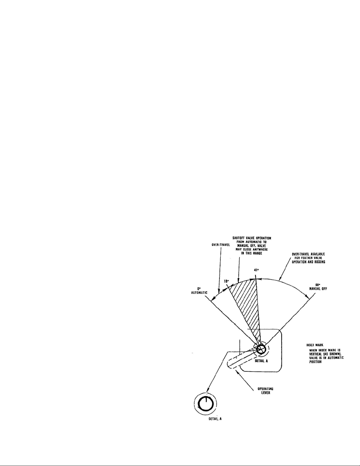
THRUSH AIRCRAFT INC - MODEL S2R-G10
AIRPLANE MAINTENANCE MANUAL
RIGGING FUEL CUTOFF AND FEATHER
Ref. Fig. 4-5 & Fig. 4-6
a. At the fuel shutoff valve, (Fig 4-5)
check to see that index mark (Detail A)
on the actuating shaft is vertical. This
is the automatic position. The
actuating arm may have to be removed
to see the index. With actuating shaft
index vertical, the arm should be
pointed outboard and down
approximately 45 degrees below level.
b. Adjust the 21712-51 rod assembly at
midrange of available threads on both
ends as in A thru D of throttle quadrant
instructions (above).
c. Connect lower end of -51 r od assembly
to the cutoff valve arm. (Index still at
top)
d. Rotate fuel cutoff valve arm 90 degrees
upward into the manual off detent.
* NOTE *
(DETENT) position, go back to the
engine.
h. Manually rotate the fuel cutoff/feather
belcrank to the feather position. Adj ust
the -79 rod assembly length to permit
the rod end bearing to attach to the
belcrank. Adjustment of the rod ends,
clevis ends or cable position through
the brackets is permitted to achieve
proper operation.
i. Cycle the control from the coc kpit while
another technician observes the cutoff
and feather valve operation. The
cockpit lever requires moderate but not
excessive force to move, and should
lock positively into the detent with an
over-center feel, particularly going fwd.
There should be at least 1/16 inch but
no more than 3/16 inch of available slot
ahead of the lever when it is in the
normal position.
The -77 and -79 push pull rod
assembly is not connected at this
point.
e. The belcrank c lamp bolts for the cutoff
should be loose. Now move the
feathering rod assembly slowly aft until
the feather valve is pulled out 3/8 inch
plus or minus 1/16. Hold this position
and tighten the 2 clamp bolts on the
belcrank.
f. Manually rotate the belcrank to move
the fuel valve back to the automatic
position, and check feather valve to be
closed. Cycle back and forth several
times to be sure that feather valve does
not move before the fuel shutoff valve
has rotated at least 45º up from the
automatic position. The feather valve
rod, fuel shutoff rod, or indexing the
shutoff arm/shaft may be adjusted to
achieve this.
g. In the cockpit, pull the emergency cut
off handle full aft and into the locked
Effective: 03/26/2010 Page 4-13
Figure 4-5:
Page 75
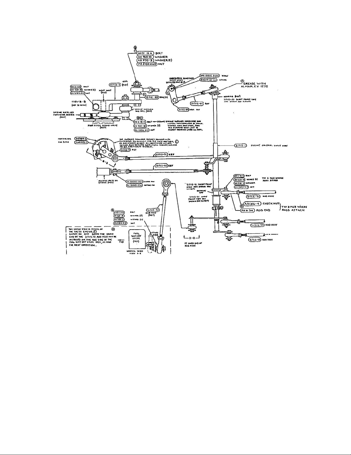
THRUSH AIRCRAFT INC - MODEL S2R-G10
AIRPLANE MAINTENANCE MANUAL
the middle hole.
Figure 4-6:
THROTTLE RIGGING:
Ref. Fig. 4-6
a. With the inboard -79 rod assembly not
connected and the 21712-71 power
control rod assembly set at midrange of
available threads, temporarily connect
the fwd end to the 21712-7 arm.
b. In the cockpit, move the throttle full fwd
and then back to the flight idle stop
briskly.
c. Set the pointer on the propeller pitch
servo protractor (by the feather valve)
at 40 degrees and install rigging pin
(1/8” diameter drill bit).
d. Adj ust the -79 rod assembly and cable
position thru the bracket on the battery
plate to allow the -79 rod to attach at
e. Remove the rigging pin and move the
power lever to full throttle position. The
pointer should move to 100 degrees
and stop out with a minimum of 1/8
inch cushion left at the power lever.
f. Return the power lever to the flight idle
position and verify that the pointer
returns to 40 degrees on the protractor.
g. Lift the latch on the power lever and
move it past the ground idle stop to full
reverse position. Check the pointer to
be at zero degrees on the protractor
with a minimum of 1/8 inch cushion left
behind the power lever.
h. Set the fwd edge of the ground idle
stop, on throttle quadrant, at ½ inch
behind the fwd edge of the flight idle
stop. This stop will be fine tuned later,
as required during ground running and
4-14
Page Effective: 03/26/2010
Page 76
THRUSH AIRCRAFT INC - MODEL S2R-G10
AIRPLANE MAINTENANCE MANUAL
flight testing.
SPEED LEVER RIGGING:
Ref. (Fig. 4-7)
a. Set the 21712-61 underspeed governor
actuator rod to midrange of available
threads and install the 21712-85 arm
on the serrated arm atop the under
speed governor input shaft.
* NOTE *
The serrated arm has 36 internal
splines to match the input shaft, and
may be indexed anywhere as
required by different airframe
manufacturers. The Thrush
requires this arm to be indexed with
the vertical peg at 50 degrees, plus
or minus 5 degrees, fwd of a line
that is 90 degrees to the engine
centerline with the under speed
governor on the minimum stop.
b. In the cockpit, set the speed lever
forward, pushing from full aft to a
position ¼ (.025”) inch short of
bottoming out in the slot.
c. Lock the speed lever in this position
with the friction knob.
d. On the engine, adjust the -79 assembly
and cable position thru the bracket on
the battery plate to allow the fwd end of
the -79 rod to line up with the hole in
the belcrank arm with the under speed
governor held on the maximum stop.
NOTE: The throttle must be fwd of
flight idle during this procedure, and the
under speed governor is spring loaded
to minimum. You’ll have to hold it in
the max position.
to positively clear the vertical peg on
the serrated arm. The under speed
governor should be on the minimum
stop.
Reverse Power Rigging Check:
a. With the speed lever full aft and the
throttle somewhere forward of flight
idle, bring the throttle slowly into full
reverse. As the throttle stop latch pin
passes the ground idle stop, the engine
linkage (TPE331-10 Linkage) will pick
up the under speed governor and
advance it to full (Max) as the throttle
lever reaches full reverse. The peg on
the serrated arm will have swung
forward, well clear of the 21712-85
arm.
CAUTION
Install all cotter pins, check all
rod end witness holes and rod
connections, tighten all check
nuts and recheck all controls for
proper operation.
* NOTE *
The procedures listed above are
presented as a general guide.
There are numerous adjustments
available to be used. To achieve
desired results, variation from this
procedure is permitted. Any
available adjustments may be
utilized to achieve engine to cockpit
rigging, provide that no thread
witness holes are ported, that
cushion exists where required and
engine inputs move from stop to
stop
e. After connecting the -79 rod to the
belcrank, check lever operation from
the cockpit. There should be a
minimum of 1/8 inch cushion at the fwd
(high) end and no cushion at the aft
end. The speed lever should contact
the bottom (aft) of the slot, and the
21712-85 arm should have swung aft
Effective: 03/26/2010 Page
4-15
ENGINE RIGGING CHECKS AND ADJUSTMENTS
This section deals only with those
performance checks and adjustments
peculiar to the Turbo Thrush aircraft.
Maintenance personnel must refer to the
current engine maintenance manual for the
Page 77
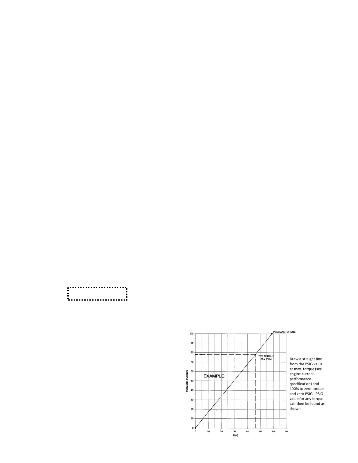
THRUSH AIRCRAFT INC - MODEL S2R-G10
AIRPLANE MAINTENANCE MANUAL
full regime of performance checks required
for proper engine operation and continued
airworthiness of the aircraft.
GROUND IDLE ADJUSTMENTS:
Refer to Fig. 4-7)
Ref. (
a. Run engine to bring oil temperature
within normal operating range.
b. Set the power lever to the ground idle
position. Check engine tachometer for
the reading indicated in the flight
manual. If the tachometer indication is
not correct, proceed as follows:
1. Shut down the engine.
2. Remove the safety wire from the
minimum speed adjustment stop
screw, located on the under
speed governor.
3. Loosen the jam nut on the
adjustable screw. Using an Allen
wrench, turn the adjusting screw
clockwise to increase speed and
counterclockwise to decrease
speed. NOTE: 1 turn –
5.5%RPM.
4. Tighten jam nut and re-safety
when adjustment is complete.
CAUTION
Fill hopper and hold the control
stick full
during all high power ground
operations to keep aircraft from
nosing over.
aft (full up elevator)
decelerates rapidly and the propeller
feathers immediately. Watch for an
immediate EGT decrease. If not, stop
engine immediately with the fuel on/off
switch. After check is completed, move
emergency cut off back to normal position.
Turn on the unfeathering pump to restore
prop on the start locks. The power lever
should be in mid-reverse position to put
prop on the start locks.
THE TORQUE SYSTEM
DESCRIPTION AND OPERATION
The direct reading torque gauge reads the
pressure at the torque sensor pressure
port of the engine by routing a hose from
the back of the gauge to the engine case.
CALIBRATION OF TORQUE
INDICATING SYSTEM
After engine overhaul, hot section
inspection or the completion of any
maintenance which may affect the torque
output of the engine, recalibrate the torque
pressure indicator per the new torque
pressure data recorded in the engine log
book.
Create a graph (Lebow plot) with gauge
pressure (PSIG) on the “x” (horizontal) axis
and percent torque on the “y” (vertical)
axis. Draw a line from zero torque and
zero pressure up to 100% torque and the
PSIG at 100% torque from the engine log
book. See example below.
EMERGENCY CUT OFF AND
PROPELL
This check is done with the power lever in
the ground idle position, the engine
running and the speed lever in the low
position. Ensure that the area ahead of
the aircraft is clear. With stick full aft and
brakes released, pull emergency cut off
lever full aft. The aircraft will surge forward
briefly, then settle as the engine
4-16
Page Effective: 03/26/2010
ER FEATHER CHECK
Page 78
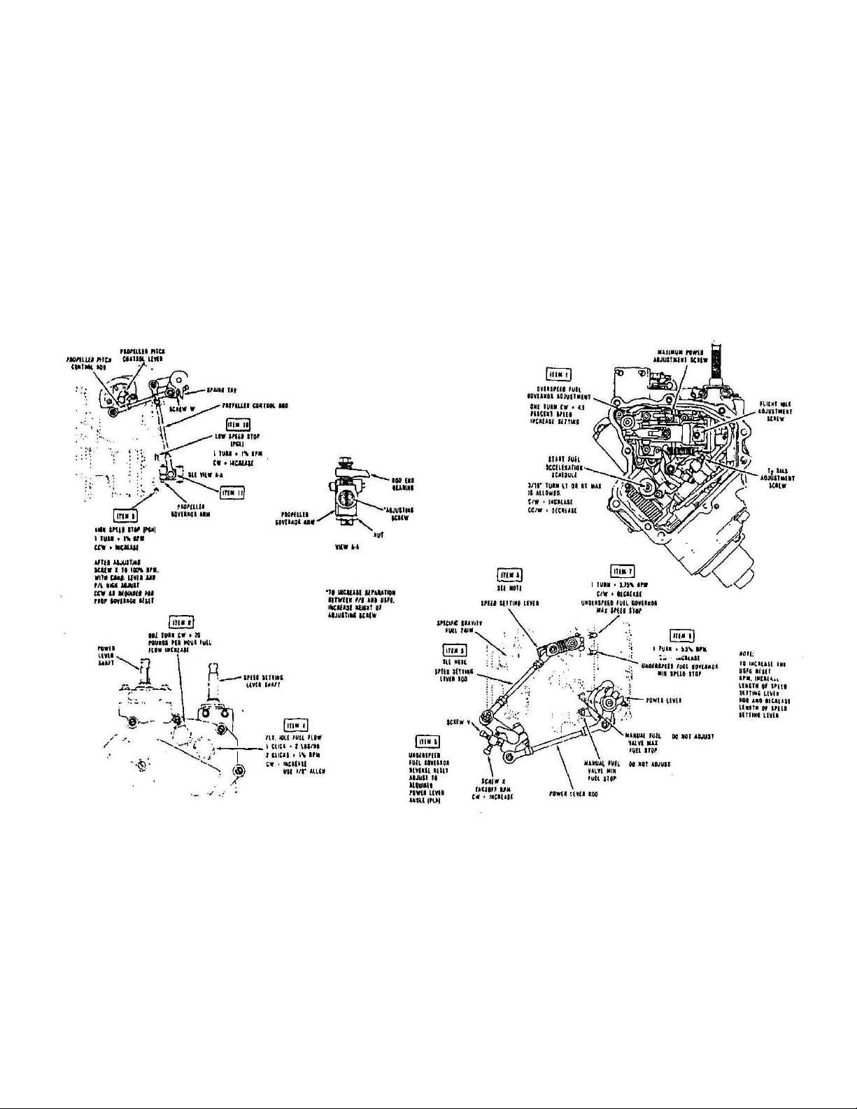
THRUSH AIRCRAFT INC - MODEL S2R-G10
AIRPLANE MAINTENANCE MANUAL
On the torque pressure indicator, change
the position of the red “bug” to correspond
with the pressure value determined above
and secure in place with a sealing
compound. On the instrument panel
adjacent to the torque pressure indicator,
affix a placard which spells out the proper
torque pressure indication at 100% torque.
For example, “59.5 PSI EQUALS 100%
TORQUE”.
Figure 4-7: Ground Idle Adjustment
Effective: 03/26/2010 Page 4-17
Page 79

THRUSH AIRCRAFT INC - MODEL S2R-G10
AIRPLANE MAINTENANCE MANUAL
THIS PAGE INTENTIONALLY LEFT BLANK
Page Effective: 03/26/2010 4-18
Page 80

THRUSH AIRCRAFT, INC – MODEL S2R G10
AIRCRAFT MAINTENANCE MANUAL
SECTION 5
FUEL SYSTEM
TABLE OF CONTENTS
GENERAL DESCRIPTION........................................................................................2
Figure 5-1: G10 Fuel System..............................................................................3
MAINTENANCE PRECAUTIONS..............................................................................2
FUEL SUB-SYSTEMS AND COMPONENTS............................................................ 4
FUEL TANK VENT SYSTEM ...............................................................................4
FUEL QUANTITY INDICATOR.............................................................................4
FUEL QUANTITY TRANSMITTER....................................................................... 4
Removal.......................................................................................................... 4
Installation.......................................................................................................5
Figure 5-2: Fuel vent System......................................................................... 5
Fuel Quantity indicating System Calibration.................................................... 5
Table 5-1: Tank Contents vs. Required Indicator Reading.............................. 6
Figure 5-3: G10 Fuel Quantity Gauge ............................................................ 7
AUXILIARY FUEL PUMP ..................................................................................... 7
Auxiliary Fuel Pump Removal......................................................................... 7
Auxiliary Fuel Pump Installation...................................................................... 7
FUEL STRAINER ................................................................................................ 7
Fuel Strainer Service Instructions ................................................................... 8
FUEL SYSTEM MAINTENANCE AND REPAIR...................................................8
USE OF FUEL PROOF SEALANTS..........................................................................8
Figure 5-4: Proper Application of Fuel Proof Sealant ........................................ 10
LEAK SEALING..................................................................................................10
RESEALING AFTER COMPLETE SKIN REMOVAL.......................................... 11
FUEL TANK PRESSURE CHECK........................................................................... 11
Required equipment...........................................................................................11
Fuel tank set-up..................................................................................................11
Pressure check Set-up.......................................................................................11
Pressure check Procedure ................................................................................. 12
Figure 5-5: Manometer Board for Leak Checking..............................................13
FUEL SYSTEM TROUBLESHOOTING...................................................................13
Table 5-2: Fuel System Trouble Shooting Chart.................................................14
ACTIVATING HOPPER (FERRY) FUEL SYSTEM..................................................16
Operating instructions for the P/N 60167 ferry fuel system ................................ 16
Figure 5-6: Hopper Ferry Fuel System..............................................................17
Effective: 03/26/2010 Page 5-1
Page 81

THRUSH AIRCRAFT INC – MODEL S2R G10
AIRCRAFT MAINTENANCE MANUAL
FUEL SYSTEM
GENERAL DESCRIPTION
Ref. Figure 5-1, 5-2 & 5-3
A 228 U.S. gallon useable fuel supply is
available for the Thrush G10. In each
wing, fuel is contained inside integral wing
tanks (wet wing fuel tanks) just outboard of
the fuselage. The left wing and right wing
fuel tanks are interconnected through a 4.5
U.S. gallon header tank that is located in
the fuselage. The fuel supply lines to the
engine are routed from the header tank
outlet finger screen through a fuel shutoff
(on/off) valve to an electric powered
auxiliary fuel pump. The auxiliary fuel
pump discharge is then routed through a
25-micron main fuel filter to the engine fuel
control unit (FCU).
The fuel tank vent system is designed to
keep fuel spillage to a minimum. The fuel
tanks are vented through tubing connected
at both the inboard and outboard ends of
the individual fuel tanks to the centrally
located vent system in the fuselage. Ram
air enters a vent scoop, on the fuselage
under the left wing and pressurizes the
vent system in order to maintain positive
pressure in the fuel tanks. The vent
system is provided with two quick drains,
located on the fuselage side skins under
each wing to drain any fuel or
condensation that might have gotten in the
tank’s outboard vent lines.
The fuel quantity gauge is located on the
lower left instrument panel. The fuel
quantity indicating system consists of two
transmitters, one indicator gauge, and a
L/H or R/H tank fuel quantity selector
switch. A transmitter, installed in each
wing tank, transmits an electrical signal to
the single fuel quantity indicator. The
indicator reads either the left or right fuel
tank individually, as chosen with the tank
selector switch, adjacent to the fuel
quantity indicator gauge on the instrument
panel.
Because of the geometry of the fuel tanks
and the fuel quantity transmitters, the fuel
quantity indicator needle reaches its upper
limit when the fuel tank contains 82 gallons
of useable fuel. Another 7.5 gallons of
useable fuel is in the tank when it is topped
off. Until the fuel level in the tank falls
below 82 gallons, one cannot depend on
the fuel quantity indicator to indicate
accurately how much fuel remains in the
tank. This is what is meant by the placard
on the indicator that says “FUEL ABOVE
82 GAL IS UNGAGEAB LE ” .
The two fuel tanks are serviced through
filler ports located on the top of both wings.
The filler ports incorporate security chains
to prevent the loss of the fuel caps.
Service the aircraft from refueling facilities
that utilize proper ground handling
equipment and filter systems to remove
impurities and water accumulations from
the bulk fuel. If filtering facilities are not
available, filter the fuel through a quality
high-grade chamois. Fuel tanks should be
serviced after the last flight of each day to
reduce condensation and allow any
entrapped water accumulations to settle to
the fuel system drains. Prior to the next
flight, fuel should be drained from each
wing tank drain, the header tank drain, and
the firewall fuel filter, until all signs of water
are gone.
MAINTENANCE PRECAUTIONS
The establishment of safe maintenance
procedures is necessary to ensure safety
of personnel and prevent damage to the
aircraft when performing fuel system
maintenance. The principle precautions
that should be enforced are as follows:
A. Perf orm fuel system maintenance in an
approved work area.
B. Ground aircraft and maintenance
stands to a common ground. Ground
points must not be painted.
C. Remove external power sources and
disconnect batteries.
5-2
Page Effective: 03/26/2010
Page 82
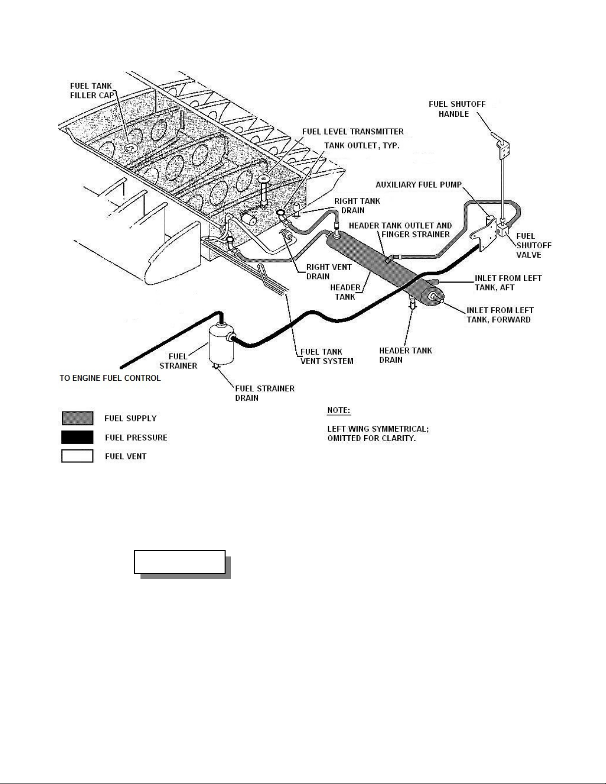
THRUSH AIRCRAFT, INC – MODEL S2R G10
AIRCRAFT MAINTENANCE MANUAL
FIGURE 5-1: G10 FUEL SYSTEM
D. Suspend all maintenance except fuel
system maintenance, unless area is
declared safe from explosive vapors.
WARNING
JET FUEL IS VOLATILE AND
VAPORS ACCUMULATE
RAPIDLY IF THERE IS NO
WIND. THESE VAPORS ARE
HEAVIER THAN AIR SO THEY
SETTLE INTO LOW SPOTS. IN
SOME CONCENTRATIONS THE
VAPORS ARE EXTREMELY
EXPLOSIVE.
E. Ensure that fire-extinguishing
equipment is readily available.
F. Use air-driven power tools only.
G. Use explosion-proof electric lights or
flashlights.
H. Wear cotton clothing to avoid possible
static electricity discharge.
I. Service, defuel, and refuel aircraft as
outlined in Section 2.
J. Do not remove components from the
fuel system until replacement
components or covers are available for
exposed openings.
K. Always replace O-rings, seals, etc.
when re-installing fuel system
components.
Effective: 3/26/2010 Page
5-3
Page 83

THRUSH AIRCRAFT INC – MODEL S2R G10
AIRCRAFT MAINTENANCE MANUAL
FUEL SUB-SYSTEMS AND
COMPONENTS
FUEL TANK VENT SYSTEM
Ref. Figure 5-2
The fuel tanks are vented to a common
manifold. Tank vent tubes extend from the
wing root to the upper forward outboard
corner of each tank. The tubes are
attached to the vent manifold by hoses.
The vent manifold is a single unit
composed of five aluminum tubes welded
together. The main cross tube is a ½”
tube. A ½” anti-siphon loop attaches the
main cross tube to the ½” ram-air tube,
which extends to the left side only. Two
¼” tubes extend from either side of the
loop just above the main cross tubes.
A ½” ram air inlet tube protrudes from the
left shin skin, below the wing, with the
opening forward. A hose connects the ram
air inlet to the ram air tube of the manifold.
The ends of the manifold main cross tube
are connected to the respective tank vent
tubes by hoses.
The two ¼” tubes are connected by hoses
to tee fittings screwed into bosses on the
inboard fuel tank ribs. The third outlets of
the tees are connected by hoses to drain
valves on the shin skins below the wings.
FUEL QUANTITY INDICATOR
Ref. Figure 5-3
A single fuel quantity indicator is installed
in the left instrument panel. This indicator
serves either the left or right fuel tank by
operation of a fuel tank-selector switch
adjacent to the indicator. The indicator
responds to the current flowing through the
fuel quantity transmitter by positioning the
needle proportionately. The instrument
face is marked in increments from empty
to full. Figure 5-1 shows the amount of
fuel in the tank at several pointer positions.
Refer to Section 8 for additional
information.
FUEL QUANTITY TRANSMITTER
The fuel quantity transmitters are installed
in the inboard aft corner of the wing fuel
tanks. Access to the transmitter is gained
by removing the inboard aft top cover
plate. The transmitters have a multi-coil
resistor and a contactor that is moved
along the resistance coil by the float arm.
The resistance thus varies in proportion to
the float arm position. The varying
resistance results in varying current flow
through the indicating circuit. As the
current flow varies the needle on the fuel
quantity indicator moves proportionately
to indicate the fuel level in that tank.
The fuel vent manifold is installed forward
of the hopper, above and forward of the
wing spar. This position puts the antisiphon loop above the tank vent tube ends
in any ground attitude, ensuring no fuel
loss through the vent system.
Before the first flight of the day,
ensure that the ram air inlet is
clear. Blockage, such as by a
“dirt dobber”, could cause fuel
starvation.
5-4
Page Effective: 03/26/2010
Removal of the fuel quantity transmitter
can be accomplished through the inboard
cover plate on the upper surface of the
wing.
A. Defuel aircraft as outlined in Section 2.
B. Remove inboard cover plate.
C. Disconnect electrical leads at the
transmitter.
D. Remove attaching screws, washers
and bushings, and carefully remove
transmitter assembly.
Removal
Page 84
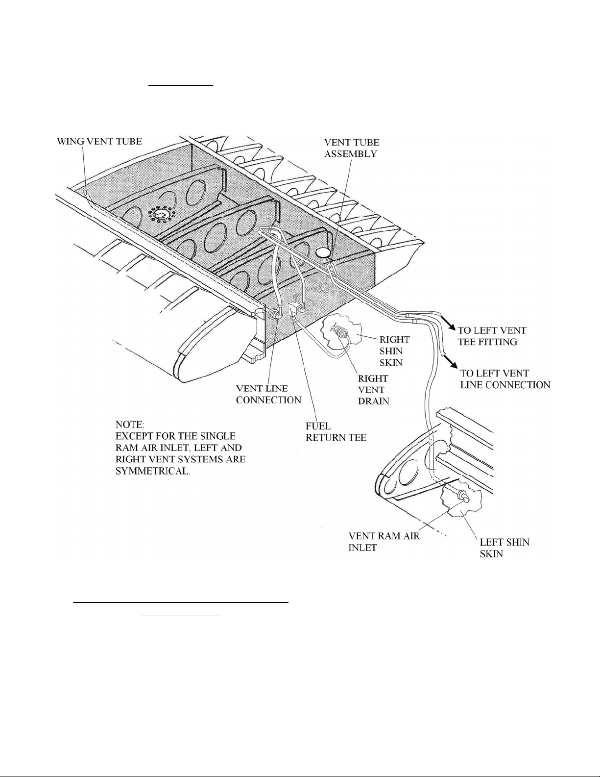
THRUSH AIRCRAFT, INC – MODEL S2R G10
AIRCRAFT MAINTENANCE MANUAL
Installation
The transmitter can be installed by
reversing the removal procedures. Do not
damage float or bend float arm when
placing the transmitter into the tank, or
incorrect readings will result.
FIGURE 5-2: FUEL VENT SYSTEM
FUEL QUANTITY INDICATING SYSTEM
CALIBRATION
The fuel quantity transmitter and indicator
have been calibrated at the factory and
should not require recalibration. However,
if for some reason the system seems to
require recalibration, carefully check out
the fuel quantity indicating electrical
system before deciding that recalibration is
necessary.
Effective: 3/26/2010 Page 5-5
A. The fuel quantity indicating system is
calibrated as follows:
B. Defuel aircraft as outlined in Section 2.
C. Level aircraft as outlined in Section 2.
D. Remove the inboard fuel tank access
cover on both wings.
E. Ensure that wing tanks are both empty.
Slowly add 2 gallons of fuel to each
wing tank.
F. Back the plug on top of the header tank
out (do not remove) to allow air to
Page 85

THRUSH AIRCRAFT INC – MODEL S2R G10
AIRCRAFT MAINTENANCE MANUAL
escape. Tighten the plug when fuel
comes out around it.
G. Slowly add additional fuel to each wing
tank until the forward fuel outlet ports
are just covered with fuel (rear outlet
ports will be covered first). If one wing
tank reaches this condition before the
other, level the airplane laterally so
that forward outlet ports in both wings
are barely covered at the same time.
* NOTE *
Because both tanks feed the
header tank, fuel will cross-feed
when there are different amounts
of fuel in the two wings.
Therefore, give the tanks some
time to equalize after fueling the
second tank.
H. Connect an APU (auxiliary power unit)
to the external power connector.
I. Turn APU on and adjust to 27.5 volts.
J. Turn battery switch ON. Readjust APU
to 27.5 volts, if necessary.
K. Place fuel quantity selector switch to
L.H. fuel tank.
L. With the transmitter float free to float on
the unusable fuel in the tank, center
the indicator needle on the “0” mark by
adjusting the trimmer screw on back of
the indicator.
M. Switch the fuel quant ity selector switch
to the R.H. fuel tank and repeat
procedure K for the right hand tank.
N. If the left and right “0” indications are
different, adjust the indicator to the
lowest one.
O. Replace the inboard fuel tank access
cover on both wings.
P. Fill both fuel tanks with 20 gallons of
fuel. Ascertain that the fuel quantity
indicator for both tanks reads within -2
to +3 gallons of the center of the “20”
mark. For reference, the width of the
“20” mark represents approximately 3
gallons.
Q. Fill both fuel tanks with an additional 2 0
gallons of fuel. Ascertain that the fuel
quantity indicator for both tanks reads
within -2 to +3 gallons of the “40”
mark.
R. Repeat step R. for the “60” and “80”
gallon marks. Ref. Table 5-1.
S. Turn off and disconnect the APU.
T. Turn battery switch OFF.
U. Watch the fuel tanks, hoses and
header tank for a while to be sure
there are no fuel leaks.
TABLE 5-1: TANK CONTENTS VS. REQUIRED INDICATOR READING
FUEL IN
TANK
INDICATOR
READING
Page Effective: 03/26/2010 5-6
Unusable 20 Gallons 40 Gallons 60 gallons 80 gallons
0 20 (-3, +5) 40 (-3, +5) 60 (-3, +5) 80 (-3, +5) 82 (-3, +5)
Greater than
82 gallons
Page 86
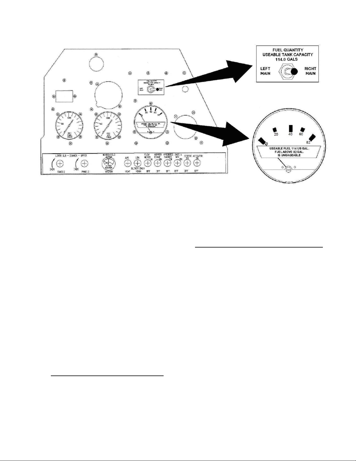
THRUSH AIRCRAFT, INC – MODEL S2R G10
AIRCRAFT MAINTENANCE MANUAL
FIGURE 5-3: G10 FUEL QUANTITY GAUGE
AUXILIARY FUEL PUMP
The electrically powered auxiliary fuel
pump is installed under the left side of the
aircraft cockpit aft of the fuel header tank.
A two-position switch labeled AUX FUEL
PUMP on the start panel controls this
pump. The pump is a positive
displacement vane type with a balancedtype relief valve, and provides a fuel
pressure of 20 ± 1psi. This pump provides
positive fuel pressure for engine starting
and may be used for continuous engine
operation in the event of engine-driven fuel
pump failure. Maintenance and
disassembly of this pump is not
authorized. Therefore, the servicing is
limited to the removal and replacement of
the pump.
AUXILIARY FUEL PUMP REMOVAL
A. Close fuel shutoff valve. Remove drain
plug and drain the aux pump.
B. Disconnect electrical connector from
pump motor.
C. Remove hoses from pump and cap
hoses.
D. Remove attaching hardware and
remove pump assembly from support
bracket.
AUXILIARY FUEL PUMP INSTALLATION
A. Install pump to support brackets and
tighten hardware.
B. Connect hoses to pump. Be sure inlet
and outlet hoses are connected
correctly.
C. Open fuel shutoff valve.
D. Connect electrical connector to pump
motor.
E. Operate fuel pump and check for fuel
leaks at lines and fittings.
FUEL STRAINER
The main fuel filter is installed on the
forward left side of the firewall. The fuel
strainer in the filter should be removed,
inspected and cleaned every 100 hours of
operation or sooner if improper fuel
circulation is suspected. (See Figure 5-1)
Effective: 3/26/2010 Page 5-7
Page 87
THRUSH AIRCRAFT INC – MODEL S2R G10
AIRCRAFT MAINTENANCE MANUAL
FUEL STRAINER SERVICE
INSTRUCTIONS
Service the fuel strainer per the following
instructions.
A. Turn airframe fuel shutoff valve to
“OFF” position. Cut, remove and
discard safety wire (not shown)
securing the wing nut on one of the
bowl retaining studs.
B. Unscrew the wing nut until the bowl
retaining bar can be removed. Be
careful not to drop the lower housing
cover.
C. Remove the lower housing cover and
pull out the fine mesh double filter
screen.
D. Clean and rinse screen free of
accumulated contaminants using
gasoline or other solvent. A
toothbrush or other fine brush may
help dislodge debris.
CAUTION
DO NOT scrape, pry or poke
mesh surfaces with sharp
objects.
E. Inspect and clean fuel filter housing as
necessary.
F. Replace filter screen with the cone
pointing down.
G. Put lower housing cover back in place
and then position the cover retaining
bar. Tighten the wing-nut as tight as
possible with finger pressure only.
H. Secure the wing nut to the filter housing
with .032” stainless steel lock wire.
I. Turn airframe fuel shutoff valve to “ON”
position. Turn fuel boost pump on and
observe 20 PSI on fuel pressure
gauge. Observe fuel filter assembly
for leaks prior to closing filter access
panel.
FUEL SYSTEM MAINTENANCE
AND REPAIR
Polysulfide sealants to AMS-S-8802
(formerly MIL-S-8802) may be used as a
thread seal or to seal minor connection
leaks throughout the fuel system. Apply
sparingly to male fittings only. Make sure
that any sealing compound or residue from
a previous seal, or any other foreign
matter, does not enter the fuel system.
CAUTION
Protect all drain openings
and fuel outlet screens
hen applying sealant.
w
Any structural repair that breaks the fuel
tank integrity will necessitate resealing of
that area of the tank. To the greatest
extent possible, repair parts requiring
sealing should be installed with faying
surfaces coated with “B” type sealant and
rivets or other fasteners installed
immediately.
eners in the fuel tanks are always
Fast
installed wet. That is, their shanks and
under the head is coated with “B” sealant
prior to installation. After installation, some
sealant will have squeezed out around the
ends. Smooth this out and add more to
completely seal the fastener ends as
shown in Figure 5-4. Use a tool or a latex
gloved finger for smoothing, not a bare
finger. Do not clean up excess sealant
with solvent.
USE OF FUEL PROOF SEALANTS
Any sealant that meets AMS-S-8802
(formerly Mil-S-8802) standards is
acceptable for sealing fuel system
components as well as other areas where
contaminant ingress needs to be
prevented. This is a polysulfide fuel
resistant sealant used on integral “wet
wing” fuel tanks as well as other areas
subject to contact with aircraft fuels,
5-8
Page Effective: 03/26/2010
Page 88

THRUSH AIRCRAFT, INC – MODEL S2R G10
AIRCRAFT MAINTENANCE MANUAL
lubricants, oils, agriculture chemicals,
water and/or weathering. They can be
painted when cured.
If you haven’t worked with this material
before, understand that it is a two-part
mixture that must be mixed properly,
according to the manufacturer’s
instructions. It is available with working life
of from ½ hour to 4 hours, and you
generally want to give yourself as much
working life as possible. It also comes in
two consistencies, “A” being thin enough to
paint on, and “B” being thicker and
requiring spreading on with a tool. They
are available in bulk or in several sizes of
kits that contain the proper proportions of
the two materials and require only
thorough mixing.
WARNING
REFER TO AND ADHERE TO
ALL MEASURES AND
PRECAUTIONS OBTAINED
FROM THE APPLICABLE
MATERIAL SAFETY DATA
SHEET (MSDS) PRIOR TO USING
OR REMOVING FUEL PROOF
SEALER AND ANY OTHER
CHEMICALS, ADHESIVES, OILS,
FUELS, SEALERS, CLEANERS,
OR SOLVENTS LISTED IN THIS
MANUAL.
When needing only small amounts of
sealer, bulk material is the more cost
effective way to go. Read the
manufacturer’s instructions thoroughly.
Generally a lot more of one part is used
than the other. Use a clean, smooth, flat
non-porous surface to mix the sealer on,
about twice as big as you think you will
need. Start by measuring out the part
used in larger proportion in the
approximate end amount needed. Then
measure out the proper proportion of the
other constituent material on top of the first
one. Mix and stir both components until a
uniform gray color is achieved. There
should be no white or black streaks in the
properly blended material. Blend the
components slowly, as violent stirring will
entrap air in the cured sealant. Do not thin
the sealant with solvents.
Thoroughly clean all surfaces to which the
sealant is to be applied immediately prior
to sealant application. Cleaning should be
accomplished with clean, lint-free paper or
cloth towels or small paintbrushes soaked
with Acetone or Methyl Ethyl Ketone
(MEK) and wiped clean. Do not let the
solvent dry on the surface, but instead
wipe it off before it dries. Always clean an
area longer and wider than the width of the
finally applied sealant to ensure no
contamination.
Fuel proof sealant is also used by Thrush
Aircraft, Inc. to seal all exposed stressed
skin fillet joints and faying (face to face)
seals, fiberglass to aluminum fillets and to
seal cockpit windows. This extra sealing
prevents water and corrosive chemical
entry into these vital structures. Fuel proof
sealant is used to seal all bolts and carrythrough structure in the chemical hopper.
A one part sealant to Mil-S-4383C may be
used as a topcoat over polysulfide fuel
proof sealers inside of the integral fuel
tanks. It has the consistency of thin syrup
and can be painted on top of all previously
sealed internal fuel tank seams. If it is
used, it must be allowed to air dry for 4
days minimum before being exposed to
fuel. Alternatively, a long curing type A
fuel proof sealer to AMS-S-8802 can be
painted on as a top coat. Either way, the
“wet wing” fuel tanks must be finished with
a topcoat over the repair and a minimum of
6” around it.
Effective: 3/26/2010 Page 5-9
Page 89
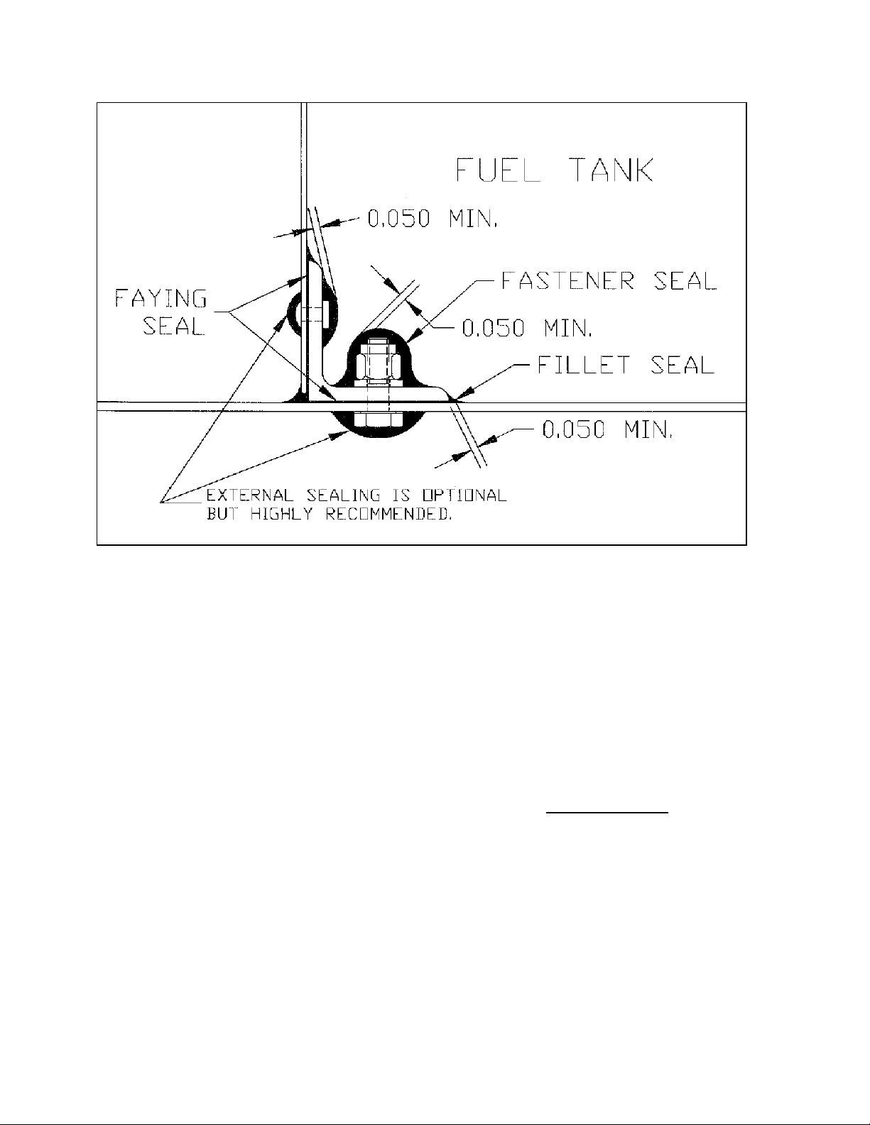
THRUSH AIRCRAFT INC – MODEL S2R G10
AIRCRAFT MAINTENANCE MANUAL
Figure 5-4: Proper Application of Fuel Proof Sealant
When working with fuel tank sealer,
cleanliness is mandatory. Something as
simple as a fingerprint or a piece of lint can
result in a fuel tank leak down the road.
Rule one is to get all the cutting, drilling,
grinding, etc. out of the way before you
start trying to seal. Having to add a hole
after sealing has begun is a recipe for a
leak. Deburr all holes and edges and
clean out all shavings.
Faying seals involve a layer of “B” type
sealant between mating surfaces. Sealant
is spread on both mating surfaces before
joining. If working on mating surfaces that
are pried apart, use a pressure applicator
to be sure sealant gets all the way
between the mating surfaces where they
are still attached. When the fasteners are
tightened, starting at one end and working
to the other, the faying sealant is squeezed
out along the edges. If a small bead does
not squeeze out, not enough sealant was
used. Ideally the faying seal should end
up .015” or about 1/64” thick.
Fillet seals are continuous lines of sealant
along the joints between two parts. The
bead squeezed out from the faying seal is
a good start, and may be sufficient when
formed into a fillet. If the bead material is
not enough to get the coverage thickness
specified in Figure 5-4, add more “B”
sealant. Use a tool or a latex gloved finger
for smoothing, not a bare finger. Do not try
to clean up excess sealant with solvent.
LEAK SEALING
Determine the approximate location of the
leak by visual inspection through the cover
plates in the lower surface of the wing.
After leak area is determined, drain all fuel
from affected tank. See Section 2 for
defueling procedures.
A. Remove the cover plates on upper
surface of wing to repair the tank leak.
Determine the exact location of the leak
source as precisely as possible.
5-10
Page Effective: 03/26/2010
Page 90

THRUSH AIRCRAFT, INC – MODEL S2R G10
AIRCRAFT MAINTENANCE MANUAL
B. Clean the general area of the leak
thoroughly. Better to clean too large of
an area than too small. If the source of
the leak is known exactly, seal it with B
type sealer. Apply an even coat of A
type sealant over the leak repair plus 3”
around it with a stiff clean brush.
C. If only the general area of the leak is
known, a larger area should be cleaned
(at least 12” past wherever the leak is
suspected) and the area coated with
type A sealant.
D. Allow the sealer to dry overnight.
E. After drying, the sealer should be
checked for air bubbles or thin spots.
Additional sealer should be applied
where necessary.
F. Reinstall the cover plates on wing
upper surface.
RESEALING AFTER COMPLETE SKIN
REMOVAL
To reseal the fuel tanks after removing or
repairing the wing skin, proceed as follows:
A. Prior to installing the wing tank skin,
vacuum tank area thoroughly to
remove all particles of dried sealant,
dirt or other foreign matter. Allow the
sealant to cure for 16 hours or more.
B. The entire tank interior should be
cleaned to remove fuel residue. All
surfaces that will receive sealant shall
be cleaned again and etched.
C. Apply type B sealant to all areas of
contact between the skin and ribs,
spars, intercostals and other skins.
D. Wet rivet the wing tank skin in place
Smooth out sealant squeezed out to
make fillet seals at all junctions.
E. Coat the entire replaced skin and all
supporting structure plus a 3” band
around it with type A sealant.
F. Reseal cover plates and fuel quantity
transmitter mounting with fuel proof
sealer.
G. To prevent water and chemical entry
into wing and empennage skin joints
and edges, fillet seal them by applying
a small bead of fuel proof sealant to all
skin edges, joints, and overlaps. The
fillets can be painted after sealer has
dried.
H. Pressure check fuel tank per the
following instructions.
FUEL TANK PRESSURE CHECK
REQUIRED EQUIPMENT
A. Pneumatic shut-off valve with an
operator that requires multiple turns
to open. This is so that pressure can
be applied gradually.
B. Manometer board per figure 5-5. (can
be locally fabricated).
C. Suitable flexible hose from shut-off
valve to wing fuel tank/system outlet.
D. Suitable flexible hose from wing fuel
tank vent to manometer board.
E. Worm clamps for attaching hoses to
wing fuel tank outlet and wing fuel
tank vent.
F. Suitable leak detection fluid and
applicator.
FUEL TANK SET-UP
When a wing fuel tank is being pressure
tested, one of the fuel outlets must be
capped, while the other is left open.
Prepare both outlet line and the fuel tank
vent line for connection to the manometer
board.
Ensure that all access hole covers are
installed properly, drain plugs are tight, and
the fuel filler cap is closed tightly.
PRESSURE CHECK SET-UP
Reference Figure 5-5, Manometer Board.
Enough colored water should be in the 1 ”
tube to extend beyond the curve slightly.
With no pressure on the 1” tube, align the
bottom of the manometer scale (the zero)
with the top of the colored water in the
manometer.
Plug shop air into the shut-off valve with
the shut-off valve closed. Connect the
Effective: 3/26/2010 Page
5-11
Page 91

THRUSH AIRCRAFT INC – MODEL S2R G10
AIRCRAFT MAINTENANCE MANUAL
pressure hose from the shut-off valve to a
wing fuel outlet, and connect the wing vent
line to the manometer inlet side. Plug the
other wing fuel outlet.
PRESSURE CHECK PROCEDURE
Crack the shut-off valve just enough to
hear air flowing through it. An increase in
pressure in the wing will be indicated by
movement of the manometer water column
up the scale side. While extreme pressure
build-up within the tank or fuel system is
prevented by the open-ended manometer
tube, too rapid of pressure build-up can
cause a pressure spike that can severely
damage the wing.
CAUTION
Apply pressure to the fuel tank
very gradually. Do not
pressurize the tank in excess of
44.0 inches of water or damage
may occur.
When pressure in the tank exceeds 38”,
start checking the tank for air leaks. Some
can be identified by hissing sounds and/or
feeling the air escaping. Feel sensitivity is
increased by wetting the hands. Leak
detection fluid will identify smaller leaks.
Turn the shut-off valve off before the water
column reaches 44”. The valve may need
to be re-opened to maintain at least 38”
while leaks are detected and solved.
Once all obvious leaks have been detected
and solved, a general check of all joints
and seams should be made using leak
detection fluid or soapy water.
When satisfied that all leaks have been
detected and solved, and with the
manometer reading between 38” and 44”,
close the shut-off valve. Start a stop-watch
or note the second hand position on a
watch and note the manometer reading.
After 5 minutes minimum has elapsed by
the watch, if the manometer reading has
not decreased by more than ¼” the
pressure check is successful. Leakage
greater than this necessitates finding and
solving the remaining leak(s).
Repeat this process until the wing holds
pressure as specified above.
Page 5-12 Effective: 03/26/2010
Page 92
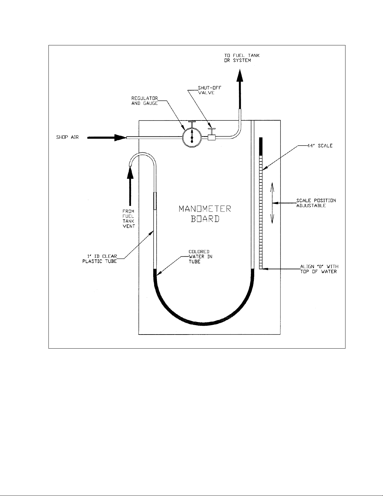
THRUSH AIRCRAFT, INC – MODEL S2R G10
AIRCRAFT MAINTENANCE MANUAL
Figure 5-5: Manometer Board for Leak Checking
FUEL SYSTEM TROUBLESHOOTING
The trouble-shooting table on the next page (Table 5-2) discusses symptoms which can be
diagnosed and interprets the results in terms of probable causes and the appropriate
corrective action to be taken. Review all probable causes given and check other listings of
troubles with similar symptoms. Presentation order is not necessarily in order of probability.
Effective: 3/26/2010 Page 5-13
Page 93

THRUSH AIRCRAFT INC – MODEL S2R G10
AIRCRAFT MAINTENANCE MANUAL
Table 5-2: Fuel System Trouble Shooting Chart
PROBLEM PROBABLE CAUSE REMEDY
No fuel quantity
indication.
No power to gauge.
Fuel tanks empty.
Fuel quantity indicator
circuit breaker open or
defective.
Defective fuel quantity
indicator or transmitter.
Loose connections or
open circuit.
eft and right fuel quant.
ndicator switch defective.
Power, ground and
transmitter checks OK.
Check fuel quantity. Service with proper
grade and amount of fuel.
Check visually. If not open, check continuity.
Reset. Replace if defective.
Disconnect wire from transmitter at indicator
not registering and attach it to an indicator
that is registering. If indicator does not
register, transmitter is defective. If the new
indicator registers, the existing indicator is
defective. Replace defective transmitter or
indicator.
Check connections and wiring. Tighten
connections; repair or replace wiring.
Check continuity and replace if defective.
Check power to gauge. If no power, check for
defective circuit breaker.
Circuit board on rear of gauge defective.
(Replace board) or entire gauge.
Check ohms to transmitter. Check for broken
Fuel indicated full
at all times.
No fuel flow to
engine.
No fuel flow to
engine. (Cont’d)
Open ground between
gauge and transmitter.
Fuel tanks empty.
Fuel line disconnected
or broken.
Header tank outlet fuel
strainers plugged.
Fuel filter element
plugged.
Fuel line plugged.
wire. Transmitter should read 0 ohms when
fuel tank is empty and 33 ohms when fuel
tank is full.
Check fuel quantity. Service with proper
grade and amount of fuel.
Inspect fuel lines. Connect or repair fuel
lines.
Disconnect fuel line from tank outlet. No fuel
indicates plugged strainer. Remove and
clean strainer and flush out tank.
Inspect filter element. Clean or replace filter
element.
Starting at fuel pump inlet, disconnect fuel
lines successively until plugged line is
located. Clean out or replace fuel line.
Page Effective: 03/26/2010 5-14
Page 94

THRUSH AIRCRAFT, INC – MODEL S2R G10
AIRCRAFT MAINTENANCE MANUAL
TABLE 5-2: FUEL SYSTEM TROUBLE SHOOTING CHART (Continued)
PROBLEM PROBABLE CAUSE REMEDY
Fuel starvation
after starting.
No fuel flow
when auxiliary
pump is on.
Partial fuel flow from
the preceding causes.
Malfunction of enginedriven fuel pump.
Fuel vents plugged.
Defective electric
auxiliary fuel pump
switch.
Open or defective
circuit breaker.
Loose connections or
open circuit.
Defective auxiliary fuel
pump.
Use the preceding isolation procedures,
checking for sufficient rate of flow. Using
the preceding remedies.
Check pump outlet during starting.
Replace fuel pump. See Section IV.
Check ram air inlet for blockage.
Pressure check each vent line. Clean or
replace vent line.
Check continuity of switch. Replace
defective switch.
Check visually. If not open, check
continuity. Reset. Replace if defective.
Check connections and wiring. Tighten
connections; repair or replace wiring.
Disconnect outlet line. With proper fuel
supply to pump, fuel under pressure
should flow from outlet. Replace
defective pump.
Fuel flow
indicator
inoperative.
(Optional Equip)
Fuel flow
Indicator comes
on but will not
show fuel flow.
(Optional Equip)
Any time you have to replace either the fuel flow indicator or the transducer,
you must be sure to have the unit calibrated to same K factor as set by the
manufacturer. It will cause bad indications if mismatched K factors are installed
together.
Defective enginedriven fuel pump bypass valve.
No voltage to
indicator.
Bad wires to
transducer or
defective transducer.
Check pump outlet during starting. See
Section IV and replace fuel pump if bypass valve is defective or installed
backwards.
Check voltage and ground wire. If voltage
is present and ground is good, replace
indicator, maintaining the same K factor.
To check transducer, remove four screws
holding wire housing to flow vane
housing. With battery power on, pass
screwdriver back and forth over wire
housing pickups. You should get a
reading on indicator. If no reading,
replace units.
*NOTE*
Effective: 3/26/2010 Page 5-15
Page 95
THRUSH AIRCRAFT INC – MODEL S2R G10
AIRCRAFT MAINTENANCE MANUAL
ACTIVATING HOPPER (FERRY)
FUEL SYSTEM
(Ref. Fig. 5-6)
A. Remove spray pump and spray pump
discharge line to spray valve. Tie-rap
any wires or cables to upper portion of
pump mount.
B. Open hopper gate box dump gate.
C. Assure hopper has been cleaned
thoroughly and there is no presence of
water or chemicals. Assure side
loading plumbing has been cleaned
and there is no presence of water or
chemicals.
D. Remove recirculation valve and install
& seal cover plate over hole in gate
box.
E. Install cap on hopper outlet fitting and
lockwire.
F. Hook up fuel line from cap to fuel
selector valve. Make sure that the fuel
line is secured to aircraft structure and
will not foul any movable controls.
G. Service hopper with approved fuel.
CAUTION
With the ferry fuel selector in
hopper position, drain all
trapped air from the hopper fuel
line by operating the fuel
strainer drain (see Figure 5-1).
Unless this procedure is
followed after each refueling, the
engine may quit when hopper
fuel is selected in flight.
A. Securely attach these instructions in
the cockpit on the hopper, directly in
front of the pilot's face at the time of
installation of the ferry fuel system.
B. In the United States, an aircraft with
this ferry fuel system installed and
connected to the normal fuel system
must be operated on a special flight
authorization (ferry permit) regardless
of whether the ferry fuel system is
actually used on any particular flight.
C. Due to vapor lock considerations, use
of automotive gasoline as an alternate
fuel is prohibited in either the wing
tanks or the hopper.
D. Do not use hopper fuel for takeoff,
landing, or flight at low altitude.
E. Use hopper fuel only for level cruising
flight above 3000 feet above ground
level. Always operate the electric fuel
pump and the ignition switch while
changing the fuel selector in flight.
Always switch fuel at or below cruise
power settings.
F. Except in emergency, do not dump
hopper fuel in flight or on the ground
with the engine running.
G. Drain the hopper sump and all other
normal fuel system sumps prior to
flight.
H. Never use the hopper as a fuel tank
unless it is completely clean and dry.
I. Remove these instructions from the
cockpit only after removal of the ferry
fuel system from the aircraft
OPERATING INSTRUCTIONS FOR THE
P/N 60167 FERRY FUEL SYSTEM
CAUTION
Operation instructions must
be strictly followed to operate
aircraft using ferry fuel
system.
5-16
Page Effective: 03/26/2010
Page 96
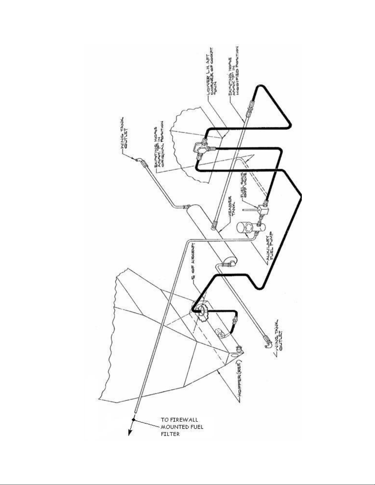
THRUSH AIRCRAFT, INC – MODEL S2R G10
AIRCRAFT MAINTENANCE MANUAL
FIGURE 5-6: HOPPER FERRY FUEL SYSTEM
Effective: 3/26/2010 Page 5-17
Page 97

THRUSH AIRCRAFT INC – MODEL S2R G10
AIRCRAFT MAINTENANCE MANUAL
THIS PAGE INTENTIONALLY LEFT BLANK
5-18
Page Effective: 03/26/2010
Page 98

THRUSH AIRCRAFT, INC – MODEL S2R-G10
AIRCRAFT MAINTENANCE MANUAL
SECTION 6
LANDING GEAR, WHEELS & BRAKES
TABLE OF CONTENTS
GENERAL DESCRIPTION..............................................................................................................2
MAIN LANDING GEAR...................................................................................................................2
MAIN LANDING GEAR ASSEMBLY......................................................................................................... 2
Removal.............................................................................................................................................. 2
Cleaning, Inspection and Repair of main gear....................................................................................2
Cleaning, Inspection and Repair of shock struts ................................................................................ 2
MAIN WHEELS AND BRAKES:................................................................................................................ 3
GENERAL DESCRIPTION ................................................................................................................. 3
MAIN WHEEL REMOVAL AND DISASSEMBLY ............................................................................... 3
FIGURE 6-1: MAIN LANDING GEAR ASSEMBLY ........................................................................... 4
INSPECTION OF MAIN WHEEL ASSEMBLY.................................................................................... 5
FIGURE 6-2: MAIN WHEEL AND BRAKE ASSEMBLY.................................................................... 6
MAIN WHEEL REASSEMBLY AND INSTALLATION ........................................................................ 6
BRAKE REMOVAL AND DISASSEMBLY.......................................................................................... 7
BRAKE SERVICING........................................................................................................................... 8
MEASURING BRAKE LINING WEAR.......................................................................................... 8
REMOVAL OF BRAKE LININGS FROM CALIPERS................................................................... 8
REPLACEMENT OF ORGANIC LININGS................................................................................... 8
FIGURE 6-3: Brake Disc and Lining Inspection Criteria .............................................................. 9
FIGURE 6-4: Brake Pad Rivet Installation ................................................................................... 9
REASSEMBLY OF ORGANIC LININGS TO CALIPER............................................................. 10
BRAKE LINING CONDITIONING PROCEDURES........................................................................... 10
Non-Asbestos Organic Linings................................................................................................... 10
BRAKE REASSEMBLY AND INSTALLATION................................................................................. 11
FIGURE 6-5: Brake Master Cylinder......................................................................................... 11
REMOVAL OF BRAKE MASTER CYLINDERS ............................................................................... 11
Disassembly and Repair............................................................................................................. 11
Master Cylinder Installation........................................................................................................ 12
BRAKE BLEEDING........................................................................................................................... 12
TAIL LANDING GEAR ..................................................................................................................12
TAIL GEAR REMOVAL..................................................................................................................... 12
Cleaning, inspection and repair of tail landing gear................................................................... 12
TAIL LANDING GEAR INSTALLATION........................................................................................... 13
FIGURE 6-6: Tail landing gear.......................................................................................................... 14
TAIL landing GEAR RIGGING.......................................................................................................... 14
DISASSEMBLY OF SPINDLE HOUSING ASSEMBLY ............................................................. 14
FIGURE 6-7: Spindle Assembly........................................................................................................ 15
CLEANING, INSPECTION AND REPAIR OF TAIL GEAR SPINDLE HOUSING ASSEMBLY. 15
TAIL gear WHEEL and tire REMOVAL AND DISASSEMBLY.......................................................... 15
INSPECTION OF TAIL LANDING GEAR WHEEL ASSEMBLY................................................ 15
TAIL landing gear WHEEL & tire REASSEMBLY AND INSTALLATION ......................................... 16
FIGURE 6-8: Tail LANDING GEAR Wheel Assembly...................................................................... 17
WHEEL AND BRAKE TROUBLESHOOTING..............................................................................18
Effective: 03/26/2010 Page
TABLE 6-1: Wheel and Brake Troubleshooting Chart..................................................................... 18
6-1
Page 99

THRUSH AIRCRAFT, INC – MODEL S2R-G10
AIRCRAFT MAINTENANCE MANUAL
LANDING GEAR, WHEELS
AND BRAKES
GENERAL DESCRIPTION
Ref. Figures 6-1 & 6-2
Each main landing gear installation
consists of a landing gear assembly, shock
strut assembly and a wheel and brake
assembly. The landing gear assembly is
bolted to the fuselage frame at two
locations and to the shock strut assembly
at one location. The shock strut assembly
is in turn bolted to the fuselage frame.
Lubrication fittings are provided for the
pivot points and for the shock strut
assembly. Lubrication should be applied
sparingly and all parts wiped clean to
prevent collection of dirt (refer to
lubrication Chart, Section 2). All landing
gear hinge points should be carefully
inspected for wear and damage during
each landing gear check. Troubleshoot
the landing gear by using the charts at the
back this section, and always places the
aircraft on jacks prior to performing
maintenance procedures on the landing
gear system.
lubrication of the spindle and axel, plus
periodic repacking of the wheel bearings.
Attachment integrity should be inspected
daily visually and by rocking the aft
fuselage from side-to-side while observing
attachment points. Tire inflation should be
checked prior to every flight.
The tailwheel is free castering when
unlocked, which is only when the control
stick is full forward. Otherwise it is locked
in the straight ahead position.
MAIN LANDING GEAR
MAIN LANDING GEAR ASSEMBLY
Ref. Figure 6-1
REMOVAL
A. Jack aircraft as outlined in Section 2.
B. Remove fuselage skins as required.
C. Disconnect flexible hydraulic brake line
at top of landing gear assembly.
D. Remove bottom bolt from shock strut
assembly.
E. Remove the bolts attaching landing
gear assembly to fuselage.
CLEANING, INSPECTION AND REPAIR
OF MAIN GEAR
The tail gear is comprised of the trunnion
attach points on the fuselage, the tail gear
spring, the tail gear spring supports, the
housing and spindle, the centering springs
and unlock control cable, the tailwheel
yoke and axel, the wheel, the tire & tube,
and various assembly and attaching
hardware..
The tailwheel spring is attached at the
forward end to a trunnion which allows
limited fore and aft movement of the
spring. The spring is supported just
forward of the bend by clamping brackets
which support it and limit fore and aft
motion. The housing and spindle is
attached to the lower end of the tailwheel
spring, and the yoke is attached to the
housing.
Service of the tailwheel consists of
6-2
Page Effective: 03/26/2010
A. Clean all parts with a suitable type
cleaning solvent.
B. Inspect all bolts, bearings and
bushings for excess wear, corrosion
and damage.
C. Check all welds for cracks.
D. Repair of the landing gear is limited to
reconditioning of parts, such as
replacing components, bearings and
bushings, smoothing out minor nicks
and scratches and repainting areas
where paint has chipped or peeled
CLEANING, INSPECTION AND REPAIR
OF SHOCK STRUTS
Ref. Figure 6-1
A. Remove top and bottom attaching
bolts, and remove complete sho ck
strut assembly from aircraft.
Page 100

THRUSH AIRCRAFT, INC – MODEL S2R-G10
AIRCRAFT MAINTENANCE MANUAL
B. Support strut under fork end and slide
a 1-1/2 inch ID sleeve over slotted
end. Apply light pressure to sleeve,
sufficient to relieve pre-load from
biscuits.
C. Remove bolt holding biscuit retainer
and disassemble unit.
D. Clean all parts with a suitable type
cleaning solvent.
E. Inspect rubber shock biscuits for
distortion, splits or deterioration.
Replace as required.
F. Inspect welds for cracks.
G. Inspect bolt holes for elongation.
H. Inspect all areas for evidence of
corrosion.
I. Repair of shock struts is limited to
replacement of parts, smoothing out
minor nicks and scratches and
repainting areas where paint has
chipped or peeled.
*NOTE*
Upper & lower shock strut
attach bolts are close
tolerance, heat treated NAS
bolt. Do not replace with AN
type bolt.
MAIN WHEELS AND BRAKES:
GENERAL DESCRIPTION
igure 6-2
Ref. f
The divided type wheels (including tail
wheel) are machined castings, consisting
of two sections called wheel halves. The
wheel halves, which are secured together
by bolts and nuts, are interchangeable,
and the complete wheel assemblies are
interchangeable according to wheel size.
The MLG wheels operate on tapered roller
bearings that rotate in hardened steel
races pressed into each wheel half. A
brake disc assembly is bolted to the wheel
and turns with the wheel. Applying
pressure to the rudder-brake pedals
individually controls the hydraulic brakes
attached to the main landing gear.
Movement of a rudder-brake pedal
operates the corresponding master brake
cylinder, attached to the aft side of the
rudder pedals, and applies pressure to the
appropriate brake. The brakes are selfadjusting, easily checked for wear, and
can be quickly overhauled by field
activities.
MAIN WHEEL REMOVAL AND
DISASSEMBLY
To remove and disassemble a main
landing gear wheel, proceed as follows:
A. Jack aircraft as outlined in Section 2.
B. Remove valve-core and deflate tire
completely.
C. Remove bolts and washers from back
plates of brake assembly and remove
back plates.
D. Remove hubcap snap ring, hubcap,
cotter pin, nut, washer, bearing and
wheel assembly from landing gear.
E. Break tire bead from wheel by using a
mallet (do not use tire irons).
F. Remove bolts, washers and nuts and
separate wheel halves. Guard valve
stem to avoid damage while removing
tire and tube.
G. Remove brake disc from brake side of
wheel. If disk sticks, pry out disc using
non-metallic instrument.
H. Remove bearing retainer snap ring,
grease seal ring, and grease seal,
spacer and bearing cone from inboard
side of wheel.
Effective: 03/26/2010 Page 6-3
 Loading...