

Thrane and Thrane A S 6390 Installation manual

SAILOR 6390 Navtex Receiver
Installation manual
Document number: 98-139768-A
Release date: October 25, 2013

Disclaimer
Any responsibility or liability for loss or damage in connection with the use of this product and the
accompanying documentation is disclaimed by Thrane & Thrane A/S. The information in this manual is
provided for information purposes only, is subject to change without notice and may contain errors or
inaccuracies. Manuals issued by Thrane & Thrane A/S are periodically revised and updated. Anyone
relying on this information should acquire the most current version e.g. from www.cobham.com/satcom
or from the distributor. Thrane & Thrane A/S is not responsible for the content or accuracy of any
translations or reproductions, in whole or in part, of this manual from any other source.
Thrane & Thrane A/S is trading as Cobham SATCOM.
Copyright
© 2013 Thrane & Thrane A/S. All rights reserved.
Trademark acknowledgements
• SAILOR is a registered trademark of Thrane & Thrane A/S in the European Union, the United States of
America and other countries.
• Other product and company names mentioned in this manual may be trademarks or trade names of
their respective owners.
• This product contains Android™ software (a Google Inc. trademark).
GPL notification
The software included in this product contains copyrighted software that is licensed under the GPL/LGPL.
The verbatim licenses can be found online at:
http://www.gnu.org/licenses/old-licenses/gpl-2.0.html
http://www.gnu.org/licenses/old-licenses/lgpl-2.1.html
You may obtain the complete corresponding source code from us for a period of three years after our last
shipment of this product, which will be no earlier than 2021, by sending a money order or check for DKK
50 to:
SW Technology/GPL Compliance,
Thrane & Thrane A/S,
Lundtoftegaardsvej 93D
2800 Lyngby
DENMARK
Please write "source for product SAILOR 6390 Navtex Receiver" in the memo line of your payment. This
offer is valid to anyone in receipt of this information.
ii 98-139768-A

Safety summary
Observe the following general safety precautions during all phases of operation, service and repair of this
equipment. Failure to comply with these precautions or with specific warnings elsewhere in this manual
violates safety standards of design, manufacture and intended use of the equipment. Thrane & Thrane
A/S assumes no liability for the customer's failure to comply with these requirements.
Ground the equipment
To minimise shock hazard, connect the SAILOR 6390 Navtex Receiver to an electrical ground and follow
the cable instructions.
Warranty limitation
The SAILOR 6390 Navtex Receiver is not a user maintainable unit, and under no circumstances should
the unit be opened beyond the outer plastic cover, except by authorized personnel. Unauthorized
opening of the unit will invalidate the warranty.
Installation and service
Installation and general service must be done by skilled service personnel. The SAILOR 6390 Navtex
Receiver is intended for use in a protected environment (-15° to +55°C) according to IEC-60945.
Compass safe distance
Compass safe distance: 20 cm (Standard magnetic compass), 20 cm (Emergency magnetic compass)
from the SAILOR 6390 Navtex Receiver.
98-139768-A iii

Preface
Approvals and standard compliance
SAILOR 6390 Navtex Receiver is approved to MED 2012/32/EU and fulfills the requirements in the following
standards:
IEC-60945 (2002), IEC-60945 Corrigendum 1 (2008), IEC-61097-6 (2005-12), IEC-61162-1 (2010-11) (aligned
with NMEA 0183 version 4.00), ITU-T X.27/V.11 (1996)
The SAILOR 6390 Navtex Receiver is approved to SOLAS Regulations IV/7, IV/14: ITU-R M.540-2 (06/90) and ITU-R
M.625-3 (10/95).
The SAILOR 6390 Navtex Receiver is approved to FCC Equipment class: RNV, Part 80 NAVTEX Receiver
80.1101(c)(1).
The approvals of the SAILOR 6390 Navtex Receiver are constantly monitored. New national approvals will be
applied for and granted and new test standards may come into force. Therefore the above list may not be complete.
Contact your authorized dealer for more information.
Record of Revisions
Rev. Description Release Date Initials
A Original document 25 October 2013 UFO
iv 98-139768-A

Table of contents
Chapter 1 About this manual
1.1 Intended readers ..............................................................................................................1-1
1.2 Manual overview ...............................................................................................................1-1
1.3 Related documentation ...............................................................................................1-1
1.4 Precautions ............................................................................................................................1-2
Chapter 2 Introduction
2.1 Introduction to Navtex ...............................................................................................2-1
2.1.1 Overview ..................................................................................................................................2-1
2.1.2 Features ...................................................................................................................................2-2
2.1.3 Connector overview ..........................................................................................................2-2
2.2 Navtex message (example) .......................................................................................2-3
2.3 System components .......................................................................................................2-3
2.3.1 Use with the SAILOR 6004 Control panel ...............................................................2-4
2.3.2 Use as a stand-alone unit with an INS ......................................................................2-4
2.4 Part numbers ........................................................................................................................2-4
Chapter 3 Installation
3.1 Unpacking and initial inspection ..........................................................................3-1
3.1.1 Unpacking ...............................................................................................................................3-1
3.1.2 Initial inspection ..................................................................................................................3-1
3.2 Installation of the SAILOR 6390 Navtex Receiver ................................3-2
3.2.1 Dimensions .............................................................................................................................3-2
3.2.2 Drilling plan ............................................................................................................................3-3
3.2.3 Navtex antenna ....................................................................................................................3-3
3.2.4 Wiring ........................................................................................................................................3-4
3.2.5 Ethernet interfaces .............................................................................................................3-5
3.2.6 Recommended cables .......................................................................................................3-6
3.3 Installation of the SAILOR 6004 Control Panel .......................................3-6
Chapter 4 Configuration
4.1 Start up .....................................................................................................................................4-1
4.1.1 To Power on and off ..........................................................................................................4-1
4.1.2 Dim and night mode ..........................................................................................................4-1
4.2 System and Navtex app installation .................................................................4-2
4.2.1 System app .............................................................................................................................4-2
4.2.2 Navtex app – daily use ......................................................................................................4-3
98-139768-A v

Table of contents
4.3 Configuration with the Service Interface .....................................................4-4
4.3.1 Accessing the Service Interface ...................................................................................4-4
4.3.2 Configuring the installation ............................................................................................4-6
4.3.3 Interface settings ................................................................................................................4-8
4.3.4 Managing Coast Station lists ......................................................................................4-15
4.3.5 System Control ..................................................................................................................4-16
4.3.6 Reboot Device ...................................................................................................................4-16
4.4 Verification .........................................................................................................................4-17
4.4.1 Verifying the installation ..............................................................................................4-17
4.4.2 NMEA Trace tool ..............................................................................................................4-18
4.4.3 Checking RF Reception Levels ....................................................................................4-19
4.4.4 Installation Tests ..............................................................................................................4-20
Chapter 5 Service & maintenance
5.1 Maintenance ........................................................................................................................5-1
5.1 Contact for support ...........................................................................................................5-1
5.1.1 System Log .............................................................................................................................5-1
5.1.2 Software update ..................................................................................................................5-2
5.1.3 Dissassembling – removing the cover .......................................................................5-3
5.1.4 Replacing the fuse ...............................................................................................................5-3
5.2 Alarms and notifications ............................................................................................5-4
5.2.1 Installation with SAILOR 6004 Control Panel .......................................................5-4
5.2.2 Installation with an INS ....................................................................................................5-5
5.3 Troubleshooting guide .................................................................................................5-6
5.4 Warranty and returning units for repair .........................................................5-8
5.4.1 Repacking for shipment ...................................................................................................5-8
Appendix A Technical specifications
A.1 SAILOR 6390 Navtex Receiver .............................................................................. A-1
A.2 NMEA PCB in SAILOR 6390 Navtex Receiver ............................................ A-2
Appendix B NMEA sentences
B.1 NMEA sentences used ..................................................................................................B-1
B.1.1 Light Weight Ethernet – LWE ........................................................................................B-1
B.1.2 Sentence characteristics and their linkage with port configuration ...........B-2
vi 98-139768-A

Table of contents
B.2 Sentence use reference ...............................................................................................B-3
B.2.1 Overview ..................................................................................................................................B-3
B.2.2 ACK - Acknowledge alarm (input) ...............................................................................B-3
B.2.3 ALR - Set alarm state ..........................................................................................................B-4
B.2.4 CRQ ............................................................................................................................................B-4
B.2.5 NRM - NAVTEX receiver mask (input/output) .......................................................B-4
B.2.6 NRX - NAVTEX received message (output) .............................................................B-5
B.2.7 RMC - Recommended minimum specific GNSS data (input) .........................B-6
B.2.8 ZDA - Time and Date (input/output) .........................................................................B-6
Glossary ..............................................................................................................................................................Glossary-1
Index ................................................................................................................................................................... Index-1
98-139768-A vii

Table of contents
viii 98-139768-A

Chapter 1
About this manual 1
1111
1.1 Intended readers
This is an installation manual for the SAILOR 6390 Navtex Receiver. It is intended for
installers of the system and service personnel. Personnel installing or servicing the system
must be properly trained by Cobham SATCOM. It is important that you observe all safety
requirements listed in the beginning of this manual, and install the system according to the
guidelines in this manual. For daily use see the SAILOR 6390 Navtex Receiver User manual.
1.2 Manual overview
This manual has the following chapters and appendices:
• Introduction
• Installation
• Configuration
• Service & maintenance
• Technical specifications
• NMEA sentences
About this manual
1.3 Related documentation
The following table shows the documents related to this manual and to the SAILOR 6390 Navtex
Receiver.
Title and description
SAILOR 6390 Navtex Receiver, User manual 98-137261
SAILOR 6004 Control Panel, Installation manual 98-136644
SAILOR 6390 Navtex Receiver, Installation guide 98-137263
Table 1-1: Related documents
Document
number
98-139768-A 1-1
Precautions
1.4 Precautions
Warnings, Cautions and Notes
Text marked with “Warning”, “Caution”, “Note” or “Important” show the following type of
data:
• Warning: A Warning is an operation or maintenance procedure that, if not obeyed, can
cause injury or death, or jeopardize the safety on board.
• Caution: A Caution is an operation or maintenance procedure that, if not obeyed, can
cause damage to the equipment.
• Note: A Note gives information to help the reader.
• Important: A text marked Important gives information that is important to the user,
e.g. to make the system work properly. This text does not concern damage on
equipment, travel safety nor personal safety.
General precautions
All personnel who operate equipment or do maintenance as specified in this manual must
know and follow the safety precautions. The warnings and cautions that follow apply to all
parts of this manual.
CAUTION! Do not use materials that are not equivalent to materials
specified by Cobham SATCOM. Materials that are not equivalent can cause
damage to the equipment.
CAUTION! The system contains items that are electrostatic discharge
sensitive. Use approved industry precautions to keep the risk of damage to a
minimum when you touch, remove or insert parts or assemblies.
1-2 Chapter 1: About this manual 98-139768-A
Chapter 2
Introduction 2
This chapter has the following sections:
• Introduction to Navtex
• Navtex message (example)
• System components
• Part numbers
2.1 Introduction to Navtex
2222
Introduction
2.1.1 Overview
The SAILOR 6390 Navtex Receiver receives Navtex messages on the international Navtex
frequencies 490 kHz, 518 kHz and 4,209.5 kHz. It can hold 2000 messages per frequency.
Messages are not affected by a power cycle. If not tagged to avoid deletion, messages are
cleared from the message log after 66
messages from and which message types you want to receive. The unit has an alarm relay
which is only activated if a message of category D is received (i.e. SAR, Mayday relay, Pirate
attack etc.). The SAILOR 6390 Navtex Receiver is always on when powered. With its LAN
interface the transponder and the display can be separated, giving access to the Navtex
information available where it is needed.
1
hours. You can customise which stations to receive
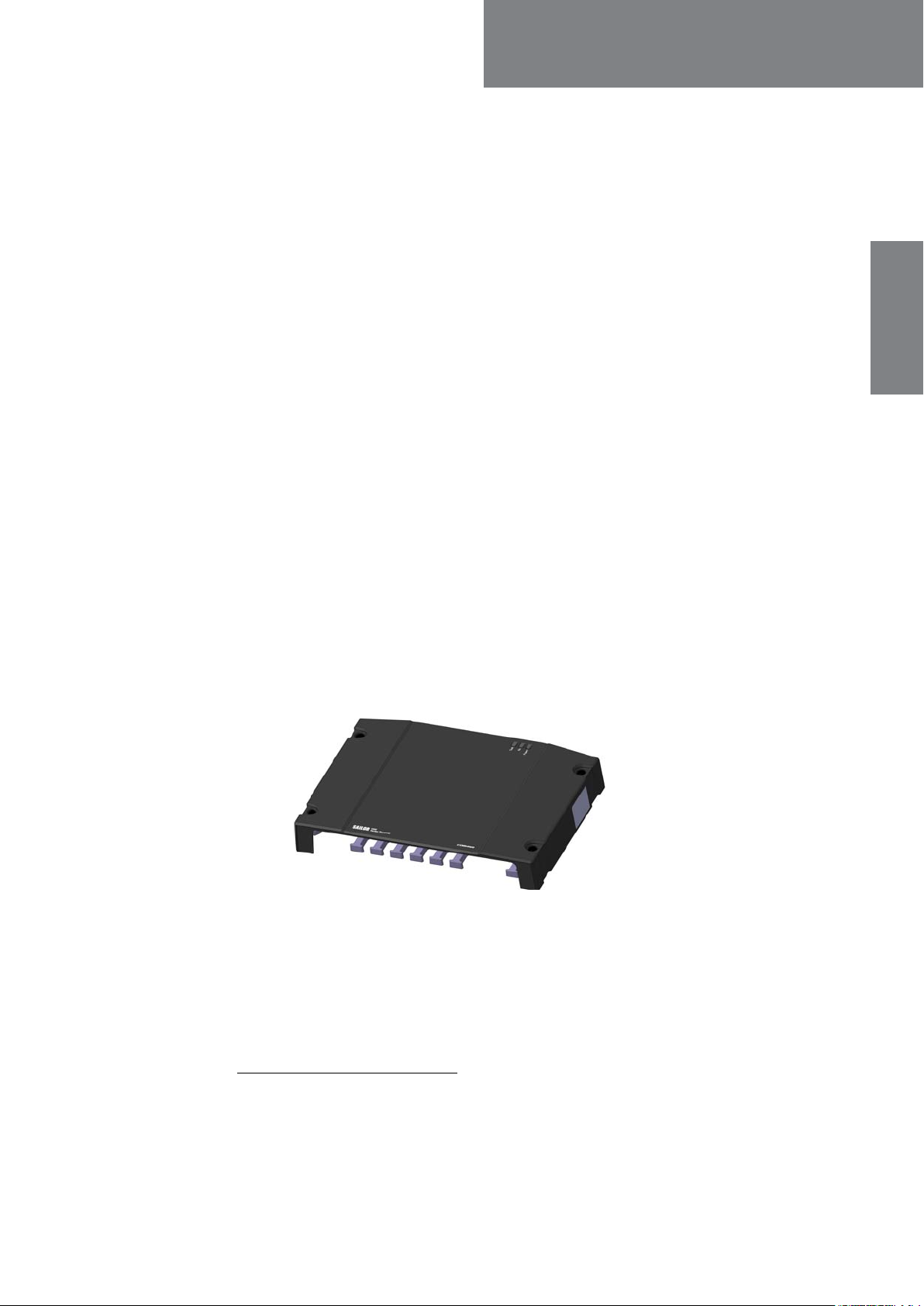
Figure 2-1: SAILOR 6390 Navtex Receiver
The SAILOR 6390 Navtex Receiver is delivered as a black box receiver which can either be
connected to the SAILOR 6004 Control Panel, a 7" touch screen, or used as a standalone
unit for integration with an INS, supporting NMEA0183. A printer can be connected to the
receiver.
The SAILOR 6390 Navtex Receiver is approved according to GMDSS (EU Marine Equipment
Directive).
1. Default value.
98-139768-A 2-1
Introduction to Navtex
2.1.2 Features
2000 messages per frequency, giving a total of 6000 messages
Printing via SAILOR 6004 Control Panel and 3rd party line printer over LAN
Integrated Navtex app for SAILOR 6004 Control Panel
Low and high impedance antenna switch
Dual LAN connector
TMA (ThraneLINK Management Application) for software upgrade
Prepared for 500 kHz NAVDAT (Software updatable)
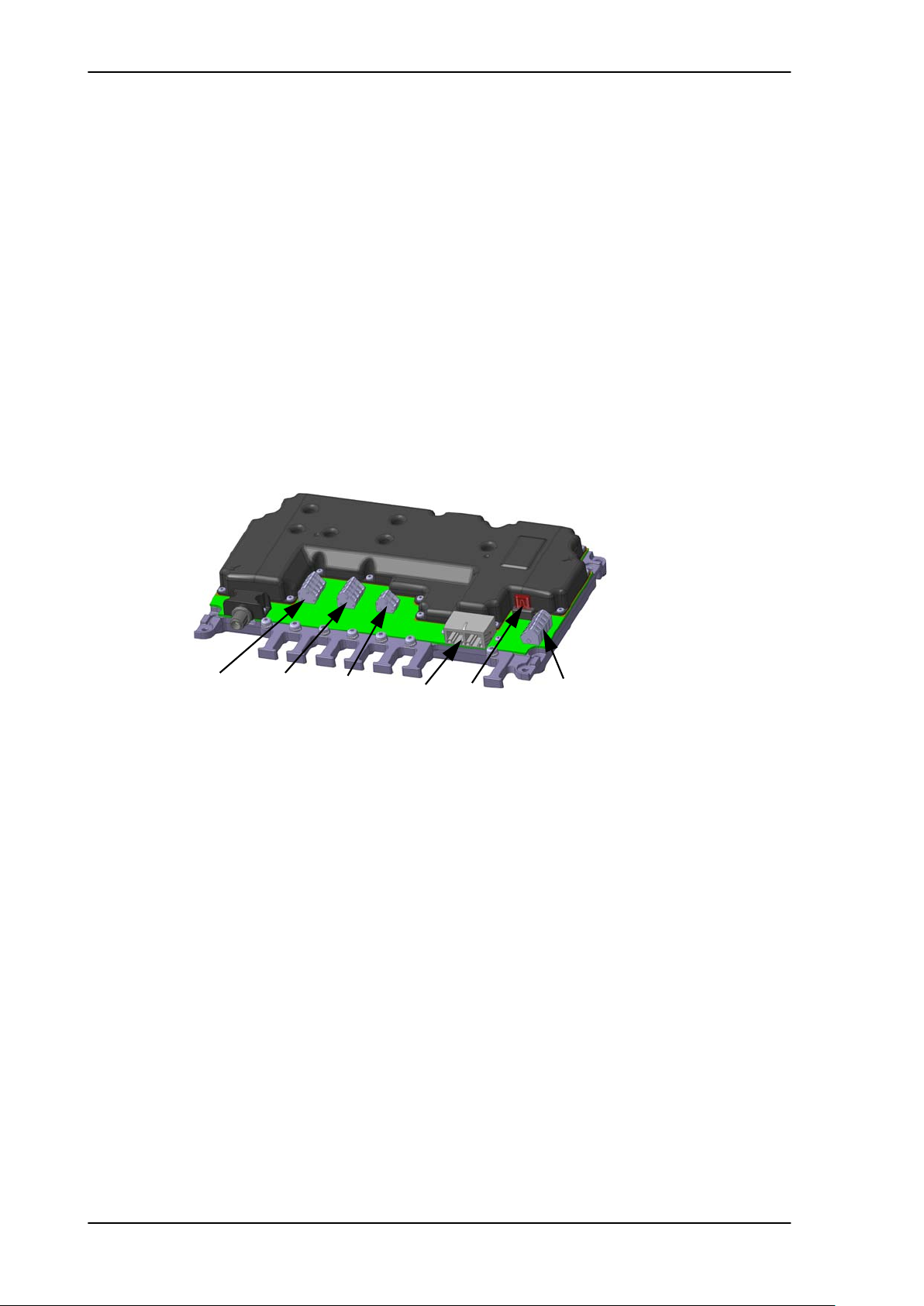
2.1.3 Connector overview
Alarm
relay
NMEA
/INS
Figure 2-2: Connector overview and fuse location
NMEA
/GPS
LAN
Fuse
12-24 VDC
2-2 Chapter 2: Introduction 98-139768-A

2.2 Navtex message (example)
The following message shows an example of a Navtex message.
ZCZC XZ28
REYKJAVIK VIA GRINDAVIK
120350 UTC SEPT 2013
NO MESSAGE ON HAND
NNNN
Message item Explanation
ZCZC Start of message (not displayed)
X Coast Station ID in the Navigational Area
2222
Navtex message (example)
Introduction
Z Message type (See The following list shows the
Navtex message types available. on page 2-10
for a list of all message types.)
28 Serial number of message 01-99: (normal), 00:
Priority
Message text REYKJAVIK VIA GRINDAVIK
120350 UTC SEPT 2013
NO MESSAGE ON HAND
NNNN End of message (not displayed)
Table 2-1: Navtex message, example
2.3 System components
The SAILOR 6390 Navtex Receiver can be used in the following contexts:
• Use with the SAILOR 6004 Control panel
• Use as a stand-alone unit with an INS
An optional printer can be connected in both use scenarios.
98-139768-A Chapter 2: Introduction 2-3
Part numbers
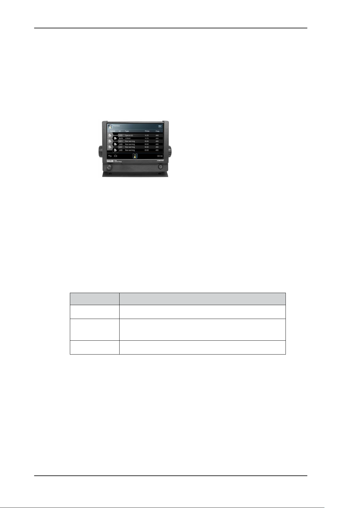
2.3.1 Use with the SAILOR 6004 Control panel
The SAILOR 6004 Control panel is the user interface for the SAILOR 6390 Navtex Receiver.
The user interface is in English. All settings that are relevant for the user are accessed
through the touch panel. Alarms and notifications are shown in the display and via NMEA.
The SAILOR 6004 Control panel has a buzzer for alarm tones and the display supports night
mode. The SAILOR 6390 Navtex Receiver has a Navtex application which is loaded into the
SAILOR 6004 Control Panel during installation.
Figure 2-3: SAILOR 6004 Control panel
2.3.2 Use as a stand-alone unit with an INS
The SAILOR 6390 Navtex Receiver also works as a stand-alone unit, integrated in the
vessel’s INS. It supports the Navtex specific NMEA sentences according to the standard
IEC 61097–6 and IEC 61162-1. For further details see the documentation of the INS.
2.4 Part numbers
This installation manual is for the SAILOR 6390 Navtex Receiver and the SAILOR 6391
Navtex system. See the part numbers below:
Part number Description
406390A-00500 SAILOR 6390 Navtex Receiver
406391A-00500 SAILOR 6391 Navtex System (SAILOR 6004 Control Panel and
SAILOR 6390 Navtex Receiver)
406004A-00500 SAILOR 6004 Control Panel
Table 2-2: Part numbers for the SAILOR 6390 Navtex Receiver
2-4 Chapter 2: Introduction 98-139768-A

Chapter 3
Installation 3
This chapter has the following sections:
• Unpacking and initial inspection
• Installation of the SAILOR 6390 Navtex Receiver
• Installation of the SAILOR 6004 Control Panel
3.1 Unpacking and initial inspection
3333
3.1.1 Unpacking
The following items are included in the delivery of a SAILOR 6390 Navtex Receiver:
• SAILOR 6390 Navtex Receiver
• User manual SAILOR 6390 Navtex Receiver
• Installation guide SAILOR 6390 Navtex Receiver
• Cable RJ45 Cat5e STP, 5 m
• Mounting tool for terminal blocks
• Cable tie 5x200 mm (8 pieces)
• Fuse puller
• Fuse (1 A)
• Screw M4-x12 TORX 20 (5 pieces)
• Screw ST3.9x19 TORX (5 pieces)
3.1.2 Initial inspection
Inspect the shipping carton immediately upon receipt for evidence of damage during
transport. If the shipping carton is severely damaged or water stained, request that the
carrier's agent be present when opening the carton. Save the carton packing material for
future use.
Installation
WARNING! To avoid electric shock, do not apply
power to the system if there is any sign of shipping
damage to any part of the front or rear panel or the
outer cover. Read the safety summary at the front of this
manual before installing or operating the system.
After unpacking the system, inspect it thoroughly for hidden damage and loose
components or fittings. If the contents are incomplete, if there is mechanical damage or
defect, or if the system does not work properly, notify your dealer.
98-139768-A 3-1
Installation of the SAILOR 6390 Navtex Receiver
3.2 Installation of the SAILOR 6390 Navtex Receiver
You can mount the SAILOR 6390 Navtex Receiver on a desktop or on a wall. Provide
sufficient space to access the connectors and the fuse. Allow sufficient space for the
cables., see Figure 3-2: Drilling plan on page 3-3.
Compass safe distance
Make sure that the SAILOR 6390 Navtex Receiver is far enough from any magnetic
compass. See the following table for the safe distance after magnetization between the
nearest point of the device and the centre of the compass at which it will produce a
deviation of 0.3°.
Device Compass safe distance
SAILOR 6390 Navtex Receiver
SAILOR 6004 Control Panel
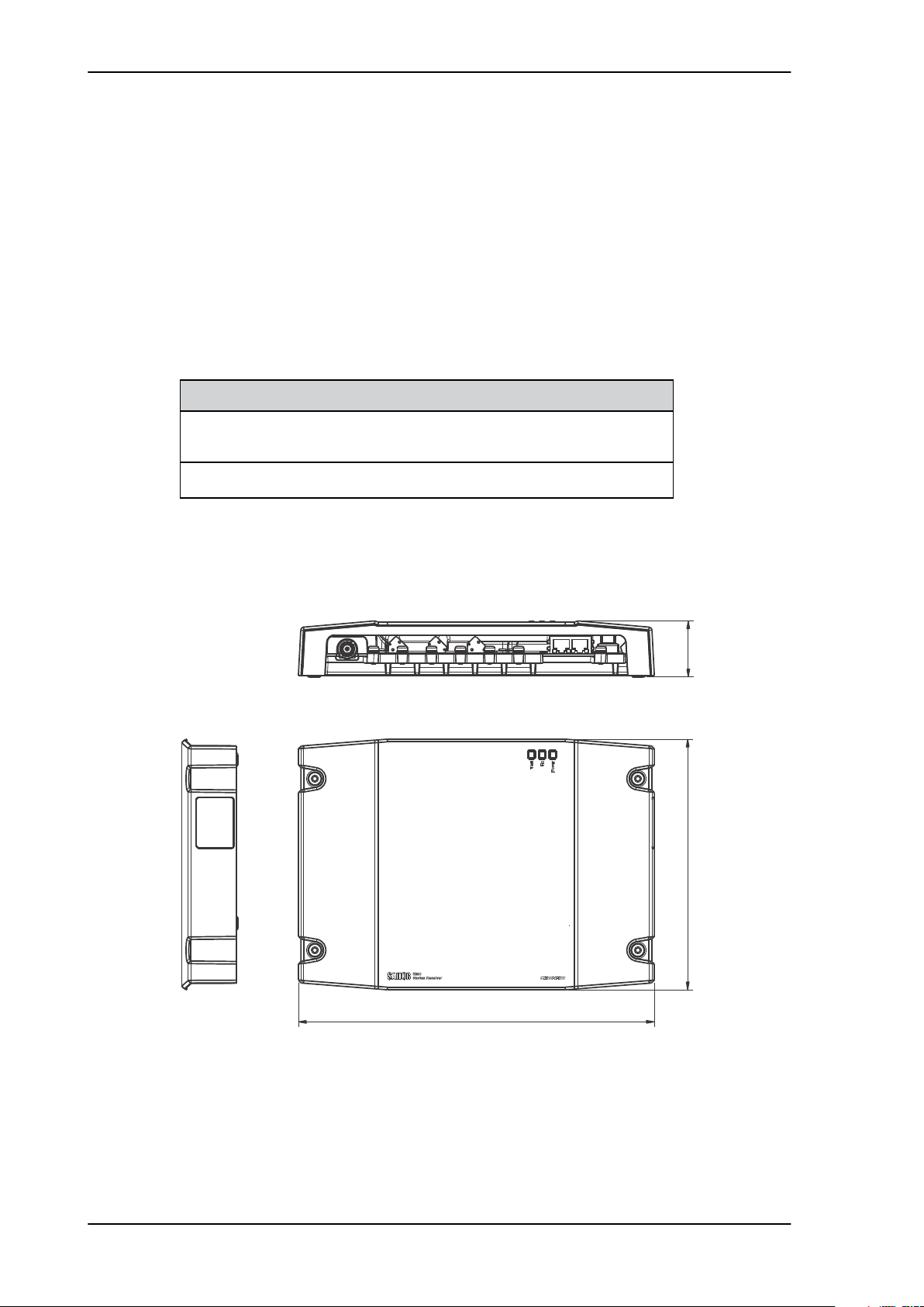
3.2.1 Dimensions
20 cm (Standard magnetic compass)
20 cm (Emergency magnetic compass)
60 cm
Table 3-1: Compass safe distances
42.5 mm
190 mm
270 mm
Figure 3-1: Dimensions
3-2 Chapter 3: Installation 98-139768-A
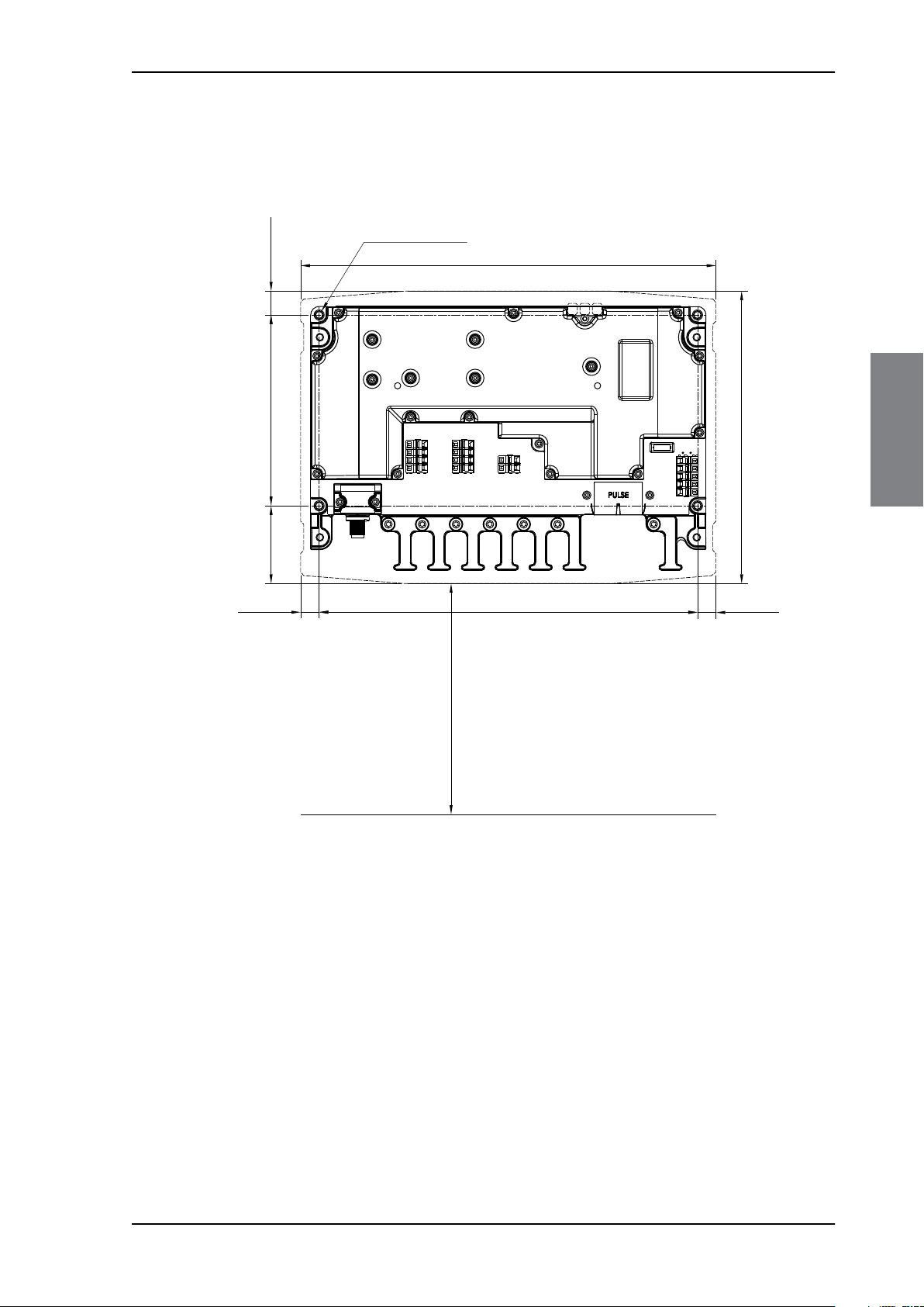
3.2.2 Drilling plan
Minimum cable entry
15.5 mm
124 mm
50.5 mm
12 mm
246 mm
12 mm
4 x M4 or hole for
self-tapping ø3.8 mm
190 mm
270 mm
150 mm
See the following drilling plan for installing the SAILOR 6390 Navtex Receiver.
3333
Installation of the SAILOR 6390 Navtex Receiver
Installation
Leave the lid of the SAILOR 6390 Navtex Receiver off until all connections to the springloaded terminals are made and initial testing is passed successfully.
3.2.3 Navtex antenna
You can fit a suitable active or passive antenna for Navtex reception. Cobham recommends
to use an active antenna suitable for tri-band Navtex reception if the environment allows it.
Suitable antennas are:
• Navcom NA 3S
• Procom NTA 3E-SHT
• Sirius A159
or similar.
Figure 3-2: Drilling plan
98-139768-A Chapter 3: Installation 3-3
Installation of the SAILOR 6390 Navtex Receiver
SAILOR 6004 Control Panel
ACC
AUX
TEST
PWR
SAILOR 6390 Navtex Receiver
NMEA IN (from eg. GPS)
NMEA IN (from INS)
NMEA OUT (to INS)
ALARM RELAY (normally closed)
+
-
+
-
+
-
Active Navtex Antenna
12 VDC @ 60 mA max.
Passive
Antenna
12-24 VDC
SAILOR H1252B Printer
VBAT+
VBAT-
PE
Shield
ON IN
ON OUT
12-24 VDC
32 VDC @ 500 mA max.
GND at talker end
GND at talker end
12-24 VDC
(internal fuse 1 A)
(internal fuse 3.15 A)
The device requires ON IN to be connected to VBAT- in order to power up.
This can be done by a dedicated switch, permanent wiring or connection
to a Cobham device supporting ON OUT (e.g. SAILOR 6004 Control Panel).
Placing the Navtex antenna
Place the Navtex receiver antenna, passive or active, as high as possible, unobstructed from
large objects. Do not place the antenna close to a transmitting MF/HF antenna, as this will
impair receiver performance.
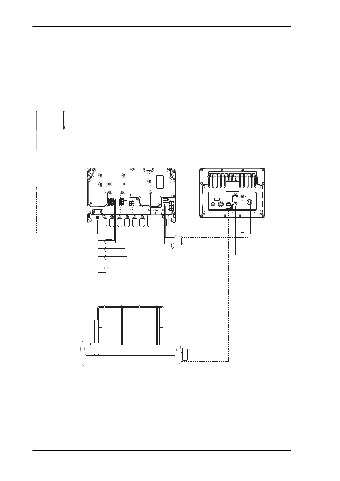
3.2.4 Wiring
Figure 3-3: Connecting the SAILOR 6390 Navtex Receiver
1. Connect the active Navtex antenna. Configuration is not necessary (auto-detect).
2. Connect to the spring-loaded terminals as shown in the above figure.
– J9: ALARM RELAY
– J10: NMEA OUT (to INS) and NMEA IN (from INS)
– J11: NMEA IN (from e.g. GPS) and GND
– PE (Protective Earth)
– 12-24 VDC
3-4 Chapter 3: Installation 98-139768-A
Installation of the SAILOR 6390 Navtex Receiver
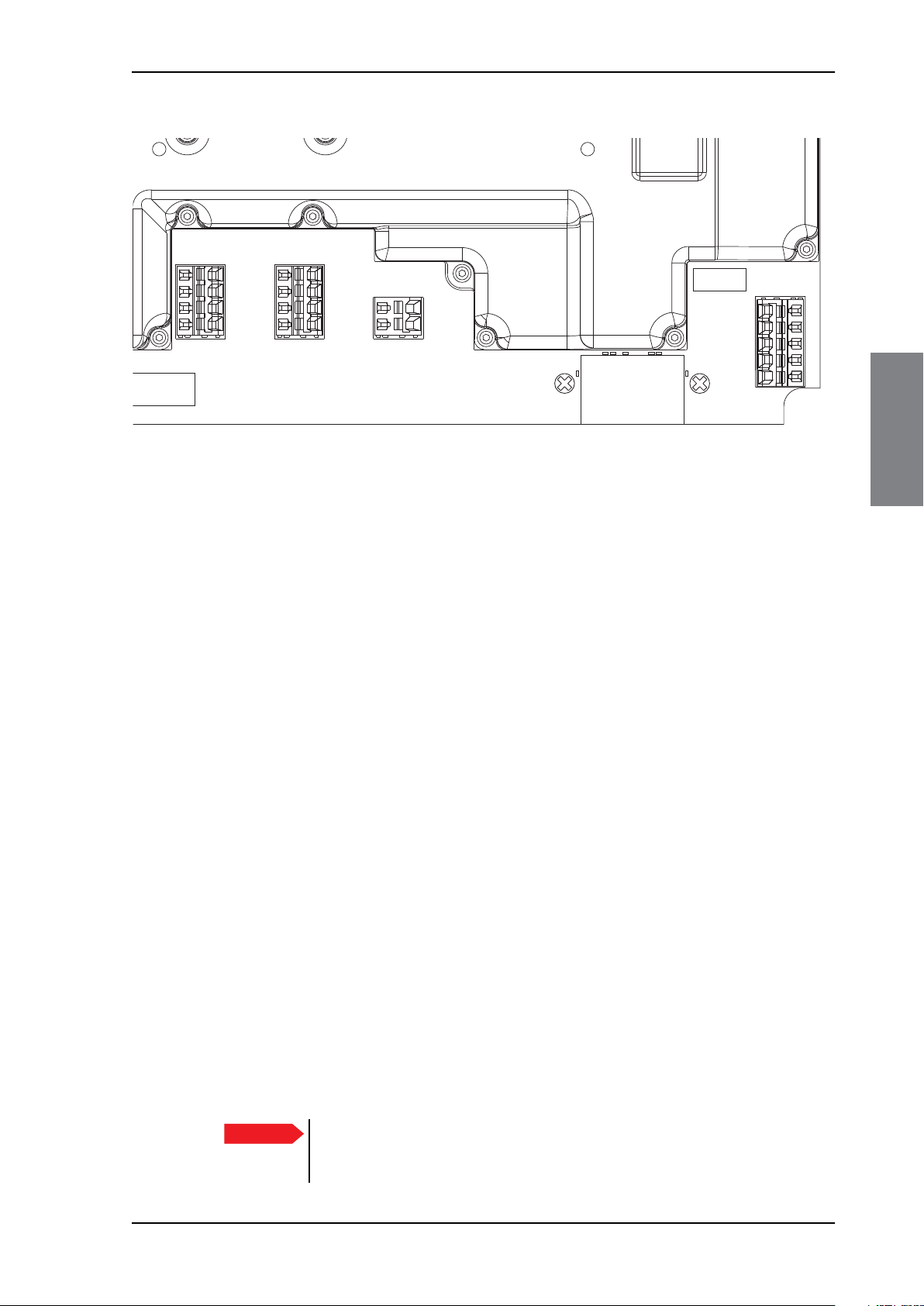
LABELLABEL
J12
J11
J10
J9
C74
C73 C64C63
R1112
R1111
R1110
J2
GND
FUSE
NMEA GPS
ALARM OUT
NMEA IN-
NMEA IN+
NMEA OUT-
NMEA OUT+
ON_OUT
/ON_IN
VBAT-
VBAT+
NMEA 2 IN-
NMEA 2 IN+
RX AUDIO
GND
ALARM OUT
3333
Figure 3-4: Spring-loaded terminals of the SAILOR 6390 Navtex Receiver (zoom)
3. Connect the SAILOR 6004 Control Panel via LAN to the SAILOR 6390 Navtex Receiver or
connect NMEA OUT (to INS) and NMEA IN (from INS).
4. Use the integrated cable relief to secure the cables with the provided cable ties.
5. Fasten the lid on the SAILOR 6390 Navtex Receiver with 4 screws (included in the
delivery).
Navtex printer interface
The optional Navtex printer interface requires a printer attached to a LAN network. Two
setups are supported:
1. Using a Control Panel as LPR print server (requires attaching a USB printer)
2. Using a third party LPR print server (requires IP address, port and queue name of that
server)
3.2.5 Ethernet interfaces
The SAILOR 6390 Navtex Receiver has two Ethernet connectors (RJ45). The Ethernet
connectors are identical, you can use any of the connectors to connect the SAILOR 6390
Navtex Receiver to the SAILOR 6004 Control Panel.
Installation
The Ethernet interface is also used for communication with the Service Interface (opens in
a web browser). For more information see Configuration with the Service Interface on
page 4-4.
LAN connector and cable
The SAILOR 6390 Navtex Receiver has two identical LAN connectors. Use one for
connecting the SAILOR 6004 Control Panel. The two connectors are of the type RJ45 with 8
leads
Important
98-139768-A Chapter 3: Installation 3-5
For GMDSS installations: Only connect units that are part of the GMDSS
LAN system. For safety and compliance reasons, the Ethernet interface is
restricted to internal communication in an isolated system.
 Loading...