

Page 1
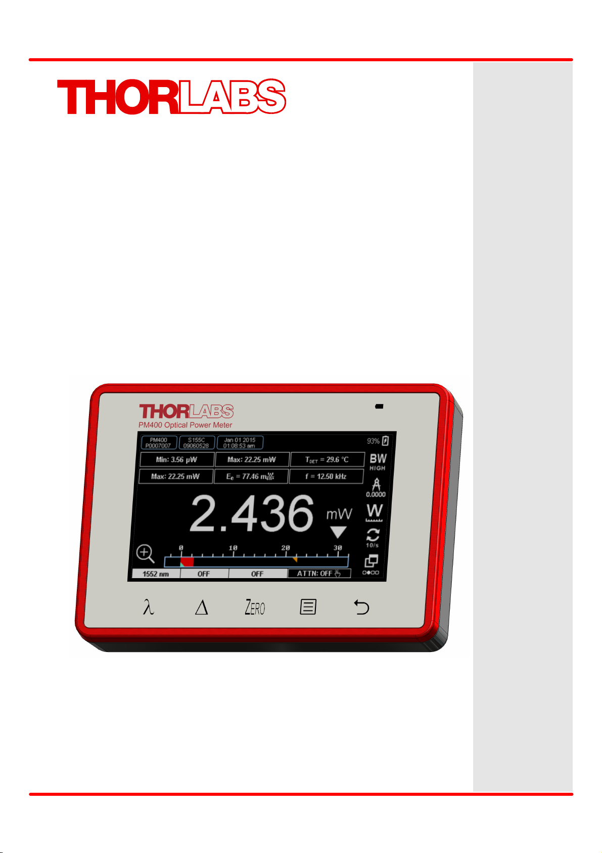
Optical Power and Energy Meter
PM400
Operating Manual
2017
Page 2

Version:
Date:
1.0
14-Jul-2017
Copyright © 2017 Thorlabs GmbH
Page 3

Contents
Foreword
3
1 General Information 4
2 Getting Started 6
3 Operating Instruction 17
173.1 Measurement Screens
203.2 Measurement Configuration
213.3 Spectral Correction
223.4 Delta Mode
223.5 Zeroing
233.6 Attenuation Correction
41.1 Safety
51.2 Ordering Codes and Accessories
51.3 Requirements
62.1 Parts List
62.2 Operating Elements
82.3 Installing Software
243.7 Data Handling
253.8 Subpanels
263.9 Main Menu
283.10 Charging the Battery
283.11 Analog and Auxiliary I/O
4 Computer Interface 29
294.1 PM400 Utility Software
324.2 Using the Instrument Drivers
5 Write Your Own Application 33
345.1 Windows XP 32bit
355.2 Windows Vista / 7 / 8 - 32bit
365.3 Windows Vista / 7 / 8 - 64bit
385.4 Simple LabVIEW Example using SCPI commands
425.5 SCPI Commands
425.5.1 An Introduction to the SCPI language
455.5.2 IEEE488.2 Common Commands
455.5.2.1 Command Summary
465.5.2.2 Command Reference
475.5.2.3 PM400 specific SCPI Command Reference
6 Maintenance and Service 54
546.1 Version Information
Page 4

7 Appendix 55
557.1 Sensor Connector Pinning
567.2 Technical Data
597.3 Certifications and Compliances
607.4 Symbols and Abbreviations
617.5 Warranty
627.6 Copyright and Exclusion of Reliability
637.7 Thorlabs 'End of Life' Policy
647.8 Thorlabs Worldwide Contacts
Page 5
We aim to develop and produce the best solution for your application
in the field of optical measurement technique. To help us to live up to
your expectations and improve our products permanently we need
your ideas and suggestions. Therefore, please let us know about
possible criticism or ideas. We and our international partners are
looking forward to hearing from you.
Thorlabs GmbH
Warning
Sections marked by this symbol explain dangers that might result in
personal injury or death. Always read the associated information
carefully, before performing the indicated procedure.
Attention
Paragraphs preceeded by this symbol explain hazards that could
damage the instrument and the connected equipment or may cause
loss of data.
Note
This manual also contains "NOTES" and "HINTS" written in this form.
Please read these advices carefully!
© 2017 Thorlabs GmbH
3
Page 6

PM400
1 General Information
The PM400 Handheld Optical Power and Energy Meter is designed to measure the optical
power of laser light or other monochromatic or near monochromatic light sources and the energy of pulsed light sources.
The space-saving, battery powered design is compatible with all Thorlabs “C-Series” Photodiode, Thermal, Pyroelectric sensors, and custom Photodiode, Thermal and Pyroelectric detectors. Combined with a fast USB device interface, these features open a wide range of applications in Manufacturing, Quality Control, Quality Assurance, and R&D for stationary and field use.
A remote control software, including drivers and applications for LabVIEW and C, makes it easy
to integrate the instrument in test and measurement systems. The software package can be
downloaded from
https://www.thorlabs.com/software_pages/ViewSoftwarePage.cfm?Code=PM100x.
1.1 Safety
Attention
All statements regarding safety of operation and technical data in this instruction manual will
only apply when the unit is operated correctly as it was designed for.
The power meter PM400 must not be operated in explosion endangered environments!
All modules, sensors and externally connected devices must only be operated with properly
shielded connection cables.
Only with written consent from Thorlabs may changes to single components be carried out or
components not supplied by Thorlabs be used.
Do not remove covers!
This precision device is only serviceable if properly packed into the complete original packaging
including the plastic foam sleeves. If necessary, ask for a replacement package.
Note
This equipment has been tested and found to comply with the limits for a Class A digital device,
pursuant to part 15 of the FCC Rules. These limits are designed to provide reasonable protection against harmful interference when the equipment is operated in a commercial environment.
This equipment generates, uses, and can radiate radio frequency energy and, if not installed
and used in accordance with the instruction manual, may cause harmful interference to radio
communications. Operation of this equipment in a residential area is likely to cause harmful interference in which case the user will be required to correct the interference at his own expense.
© 2017 Thorlabs GmbH4
Page 7

1 General Information
Ordering Code
Description
PM400
Handheld Power / Energy Meter Console
1.2 Ordering Codes and Accessories
Included Accessories
·
BNC-to-3.5-mm adapter for Analog output
·
USB cable A to Mini-B
Optional Accessories
·
PM400-PMA post-mount adapter – fix to back with two M3 screws
·
PM400-AUX adapter card with GPIO ports and a sensor for ambient temperature and
relative humidity measurement.
·
TSP-TH external NTC (thermistor temperature sensor)
Please visit our homepage http://www.thorlabs.com for various accessories like fiber adapters,
posts and post holders, data sheets and further information.
1.3 Requirements
These are the requirements to the PC intended to be used for remote operation of the PM400.
Hardware Requirements
CPU: 1 GHz or higher
RAM: 256 MB
Graphic card Min. 32 MB memory
Hard disc Min 100 MB free storage space
Interface free USB2.0 port, USB cable according the USB 2.0 specification
Software Requirements
The PM400 software is compatible with the following operating systems:
·
Windows® XP (32-bit) SP3
·
Windows® Vista (32-bit, 64-bit)
·
Windows® 7 (32-bit, 64-bit)
·
Windows® 8.1 (32-bit, 64-bit)
·
Windows® 10 (32-bit, 64-bit)
For operation of the PM400, also an NI-VISA (version 5.4. or higher) is required. This NI-VISA
engines comes with the Thorlabs GmbH PM400 installation package, but can be downloaded
also from National Instruments' website www.ni.com. A LabVIEW Engine 2015 is included as
well.
© 2017 Thorlabs GmbH
5
Page 8
PM400
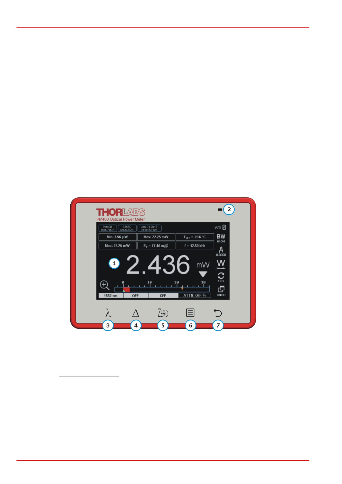
1
Capacitive Touchscreen Area for general operation
2
Battery Charging Indicator
3 to 7
Additional Capacitive Touch Buttons for:
3
Spectral Correction (enter operating wavelength)
4
Delta mode
5
Zeroing
6
Device Main Menu
7
Return / Reset
2 Getting Started
2.1 Parts List
Inspect the shipping container for damage.
If the shipping container seems to be damaged, keep it until you have inspected the contents
and you have inspected the PM400 mechanically and electrically.
Verify that you have received the following items within the package:
1. PM400 Optical Power Meter Console
2. BNC-to-3.5-mm-Audio Adapter for Analog output
3. USB cable A to Mini-B
4. This Operating Manual
5. Certificate of Calibration
2.2 Operating Elements
Front Panel
© 2017 Thorlabs GmbH6
Page 9
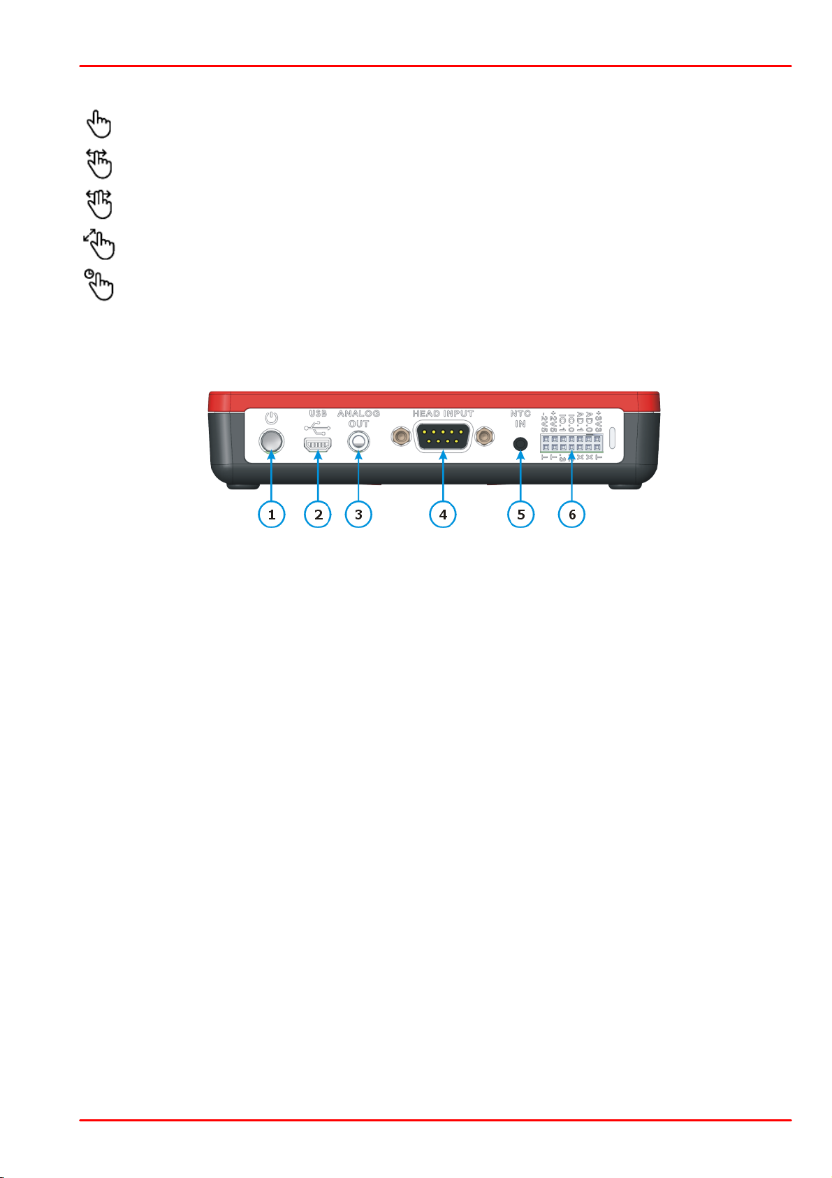
The capacitive touch screen allows gesture operation:
Click (short) for buttons, drop-downs etc.
Horizontal swipe (change view)
Horizontal scroll (graph control). Requires two fingers! 1)
Zoom (graph control) either with thumb and index or index and middle finger. 1)
Press > 2 seconds and release
1
Device On / Off button
2
Mini-B USB connector for remote control, SD card access and charging
(Charging via PC @ 0.5 A, charging via adapter @ 1 A)
3
Analog Output Signal
2P audio jack Ø 3.5 mm
4
9 Pin DSUB for connection of Thorlabs C-Series Power and Energy sensors;
Custom detectors
5
Connector for External Temperature Sensor TSP-TH (NTC)
3P audio jack Ø 2.5 mm
6
Auxiliary connector DIL 14 pin for digital I/O and external environmental module
to ambient temperature and humidity.
1
) These gestures are enabled only in the viewer mode of the graph display.
Top Panel
2 Getting Started
© 2017 Thorlabs GmbH
7
Page 10
PM400
2.3 Installing Software
For the PM400 a software package is available on the Thorlabs GmbH website:
https://www.thorlabs.de/software_pages/viewsoftwarepage.cfm?code=PM100x
This software package contains:
·
NI VISA 5.4.1 Runtime
·
NI LabView Runtime 2015
·
Thorlabs PM100 Utility Version 5.8
·
Thorlabs Instrument Communicator 2 Version 1.5.0
·
Thorlabs DFU (Device Firmware Update) Wizard Version 2.6
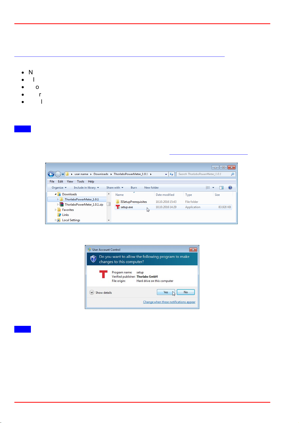
Download the ZIP archive and extract the files to your computer. Below, the appropriate installation steps are shown fore installation to a Windows 7 64 bit operating system.
Note
The described below procedure applies to a computer without installed NI VISA 5.4.1 Runtime
and NI LabView Runtime 2015. If these components are installed already and correctly recognized, the installer skips the installation and resumes with Thorlabs software installation.
Start the installation by executing the file setup.exe as shown in above screenshot.
Click "Yes" to start installation.
Note
You need administrator privileges to install the software!
© 2017 Thorlabs GmbH8
Page 11
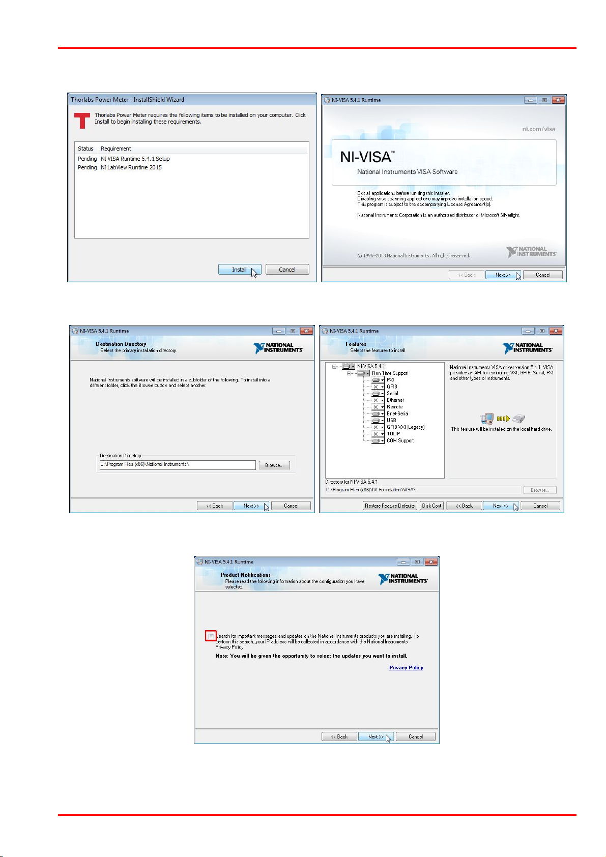
NI VISA 5.4.1 Runtime
Click "Install", then "Next" to continue.
2 Getting Started
Click "Next" to continue.
We recommend to uncheck the box that is marked red. Then click "Next" to continue.
© 2017 Thorlabs GmbH
9
Page 12
PM400
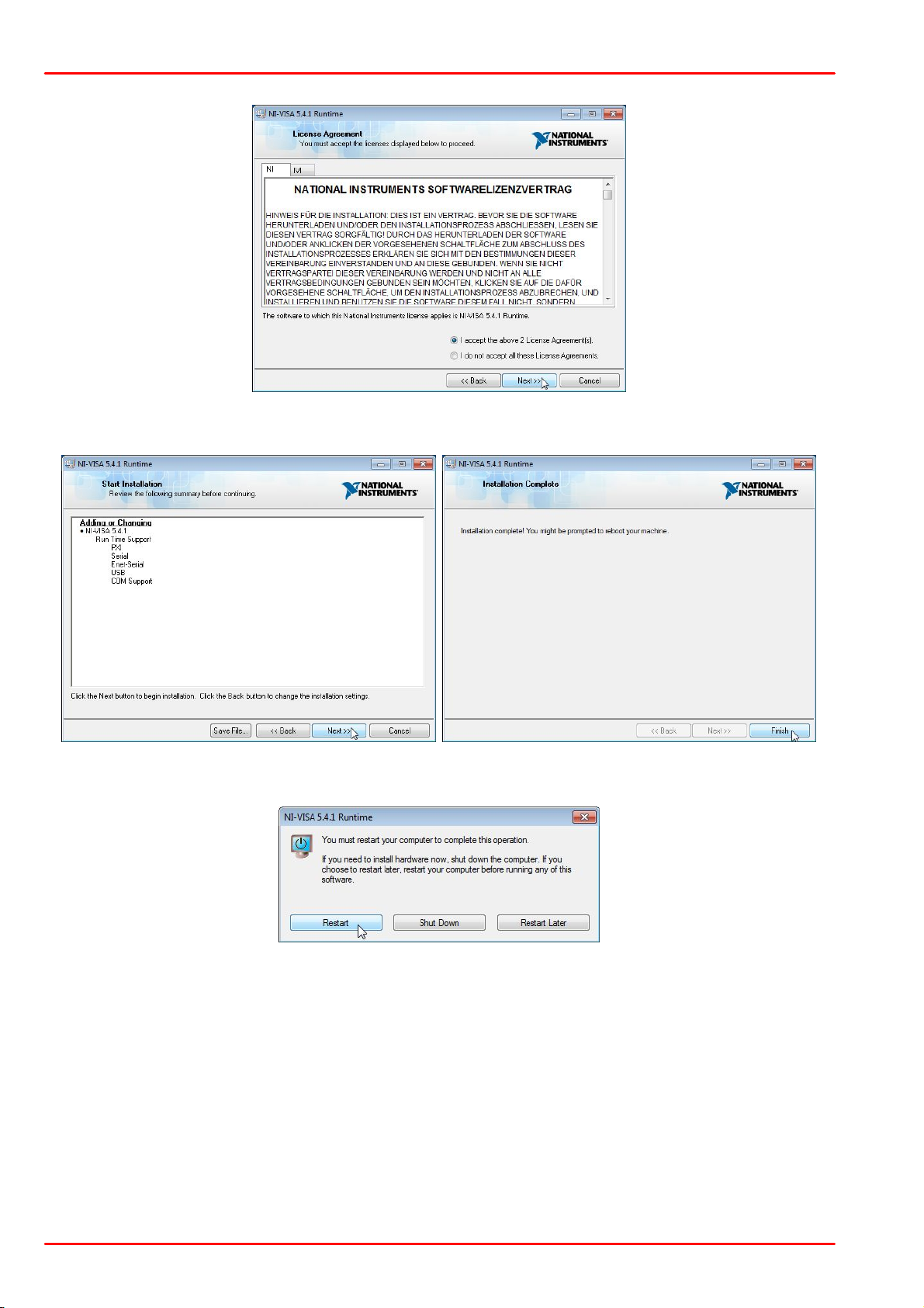
Select "I accept..." if you do so, then click "Next" to continue.
Click "Next" to continue.
You might be prompted to restart the computer. In order to ensure proper installation of subsequent components, it is strongly recommended to restart your computer now.
© 2017 Thorlabs GmbH10
Page 13
2 Getting Started
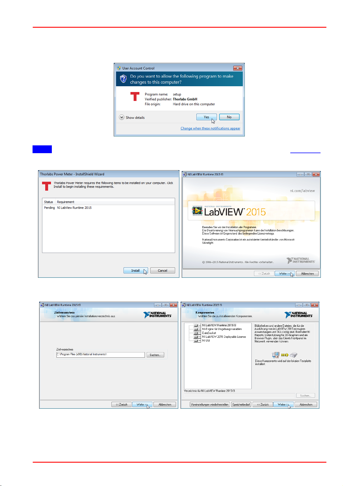
NI LabView Runtime 2015
After rebooting the computer, the installer continues automatically.
Note If the installation process does not resume automatically, please execute the setup.exe
anew.
Click "Install", then "Next" to continue.
Click "Next" to continue.
© 2017 Thorlabs GmbH
11
Page 14
PM400
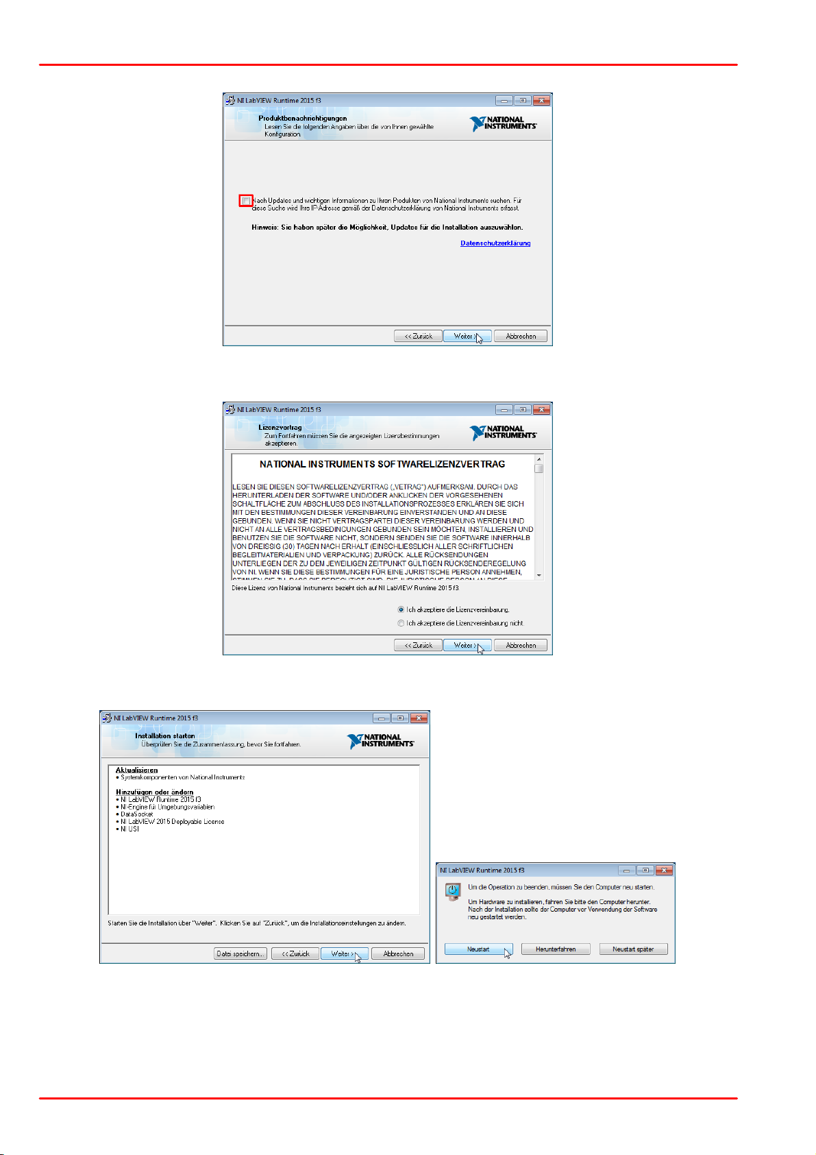
We recommend to uncheck the box that is marked red. Then click "Next" to continue.
Select "I accept..." if you do so, then click "Next" to continue.
Click "Next" to continue.
© 2017 Thorlabs GmbH12
Page 15
2 Getting Started
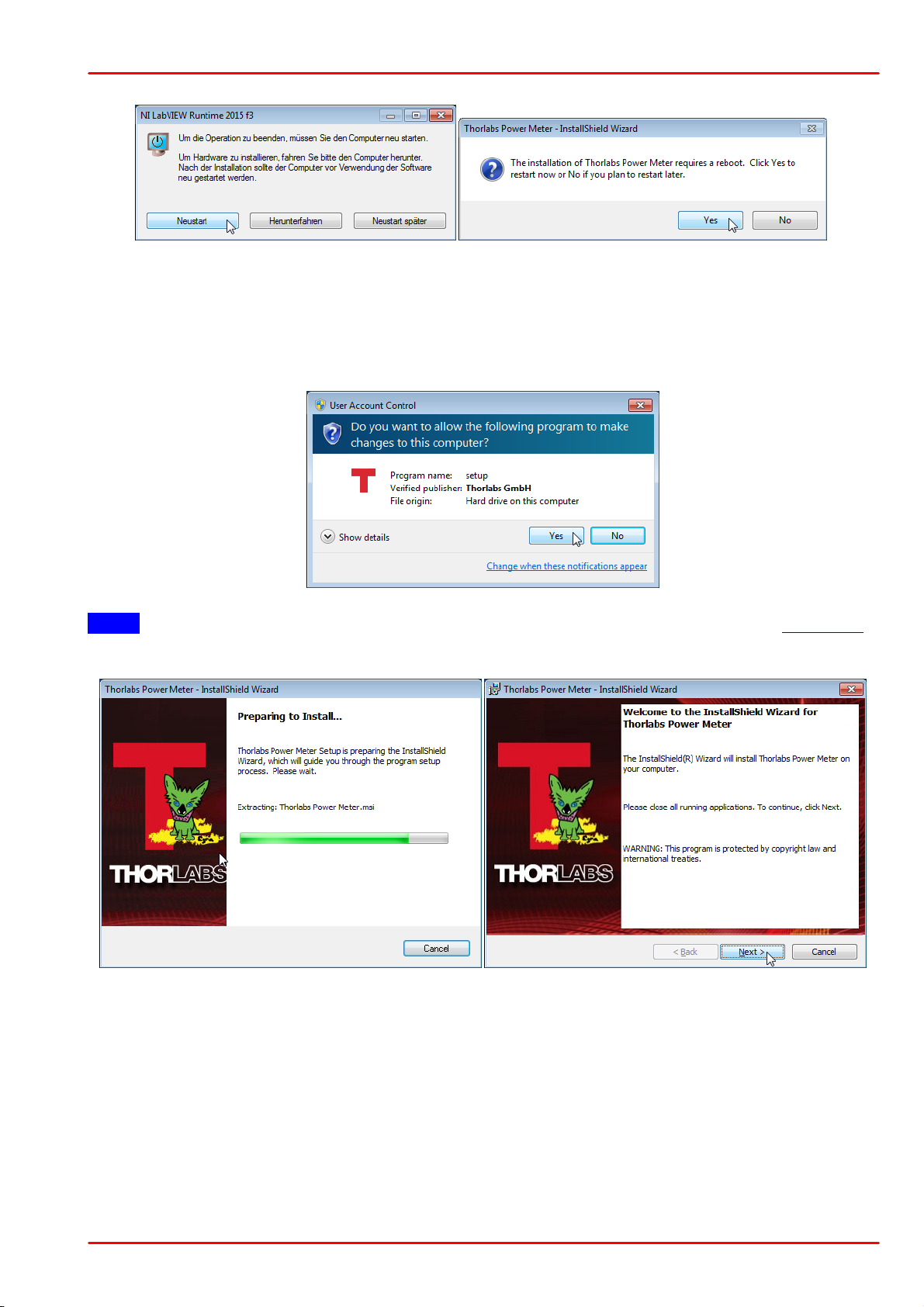
You might be prompted to restart the computer. In order to ensure proper installation of subsequent components, it is strongly recommended to restart your computer now.
Installing Thorlabs Software
After rebooting the computer, the installer continues automatically.
Note If the installation process does not resume automatically, please execute the setup.exe
anew.
Click "Next" to continue.
© 2017 Thorlabs GmbH
13
Page 16
PM400
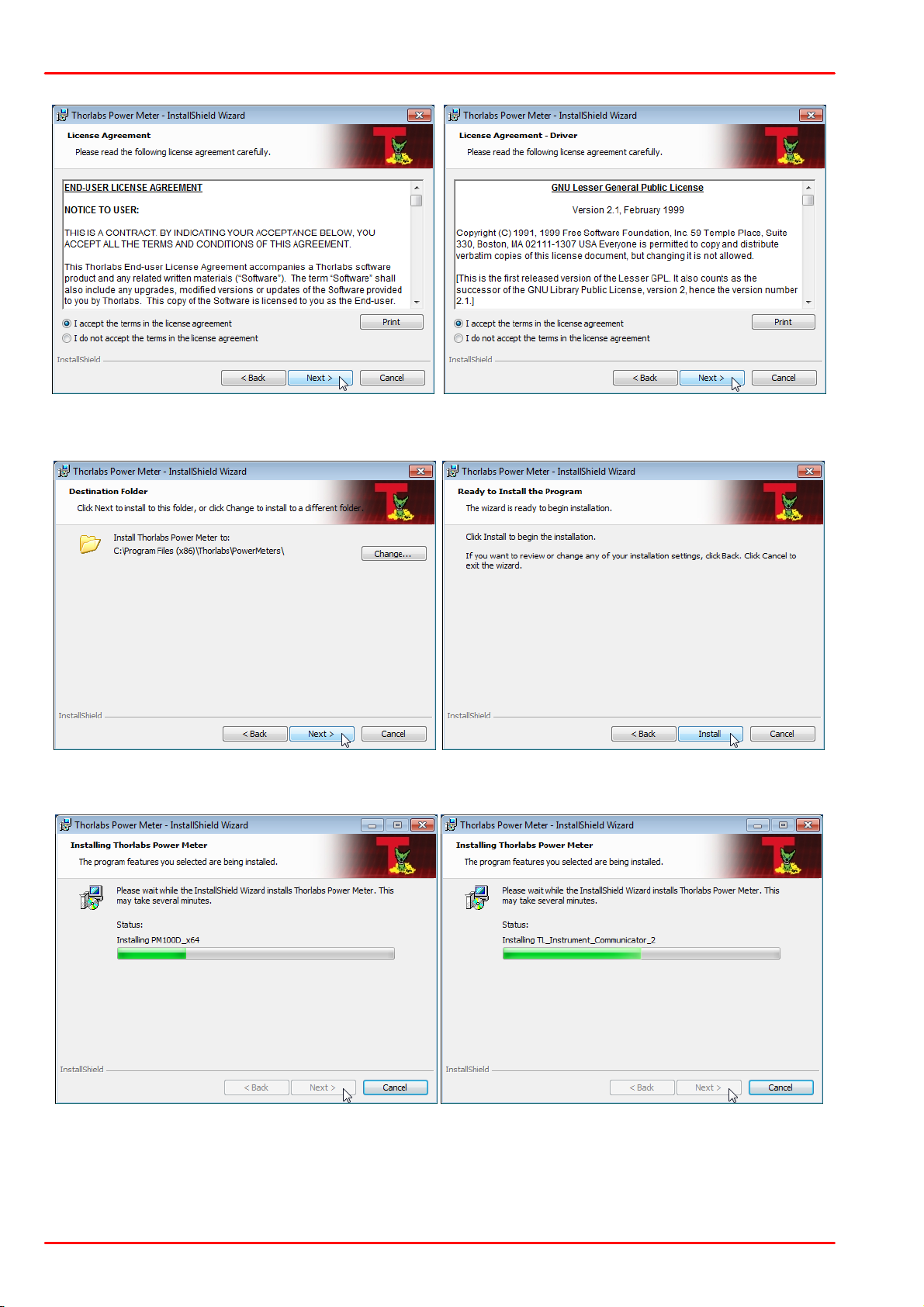
Select "I accept..." if you do so, then click "Next" to continue.
Click "Next", then "Install" to continue.
© 2017 Thorlabs GmbH14
Page 17
2 Getting Started
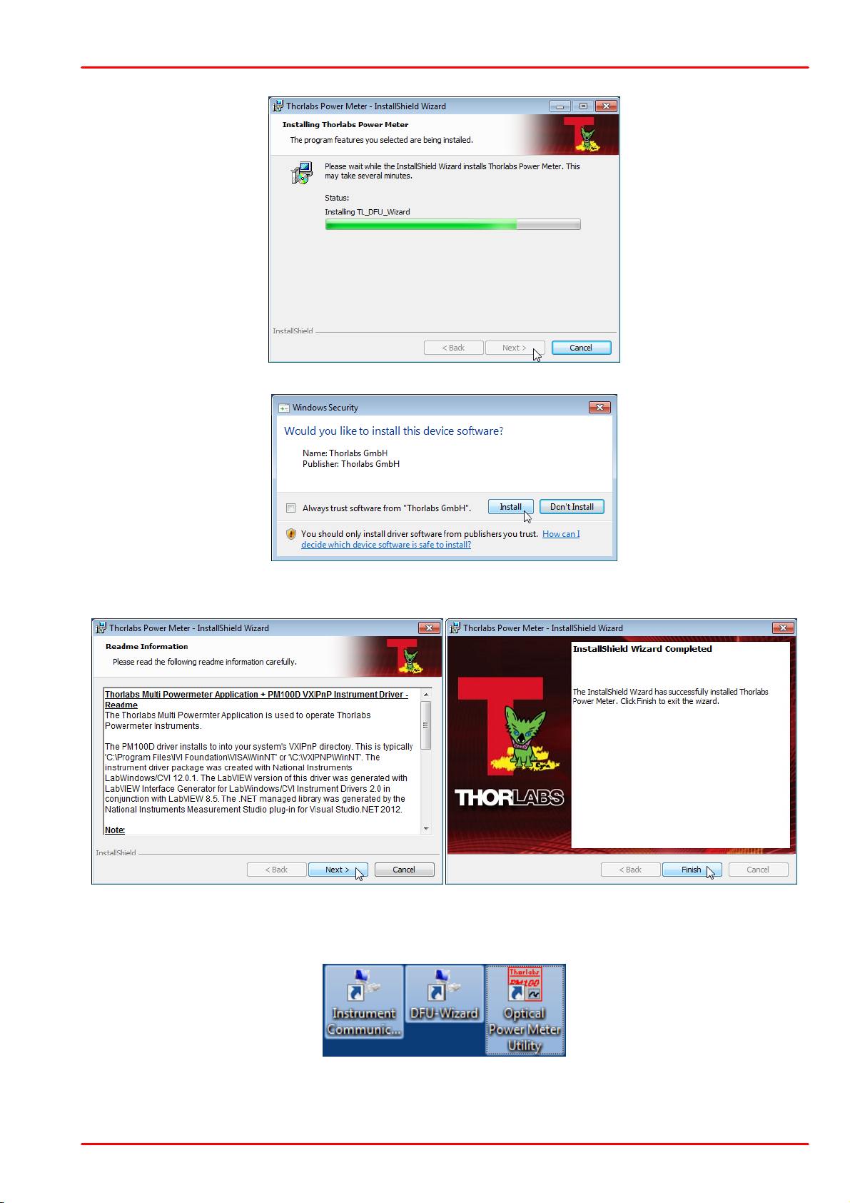
Click "Install" to continue.
Read the information, then click "Next". In the last window click "Finish". On the desktop three
new icons appear that allow to execute the installed software.
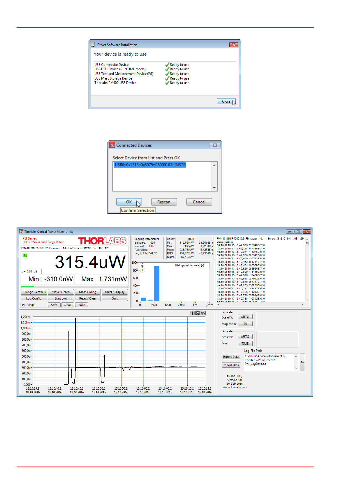
Switch on your PM400, and connect it to a free USB port using the USB cable that was attached. The required driver software is being installed.
© 2017 Thorlabs GmbH
15
Page 18
PM400
Start the application from the Optical Power Meter Utility icon. The GUI opens and you will be
prompted for device selection:
© 2017 Thorlabs GmbH16
Page 19
3 Operating Instruction
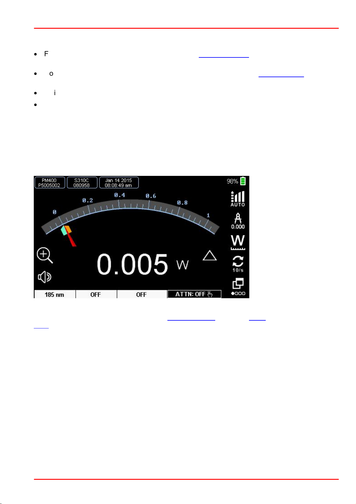
Needle Display - Thermal Sensor ((Zoomed Scale)
Bandwidth Setting
Resolution of the digital
value
Toggle to change units
Display Update rate
Next Screen
3 Operating Instruction
·
For first use, connect the PM400 to a suitable charging device and charge the battery for
4 hours.
·
Connect the optical sensor (C-Series - red DSUB connector) to the DSUB jack (4) on the top
of the device.
·
Switch on the PM400.
·
The PM400 starts in the last view that was used before shutdown.
3.1 Measurement Screens
Needle Screen
Analog needle simulation with digital measurement value. The needle has a factor 10 zooming
function. Further, there are indicators for the extreme values that can be set to the actual value
by the reset key.
The lower display bar shows from left the set wavelength, status of Delta measurement and the
Zero compensation value.
© 2017 Thorlabs GmbH
17
Page 20
PM400
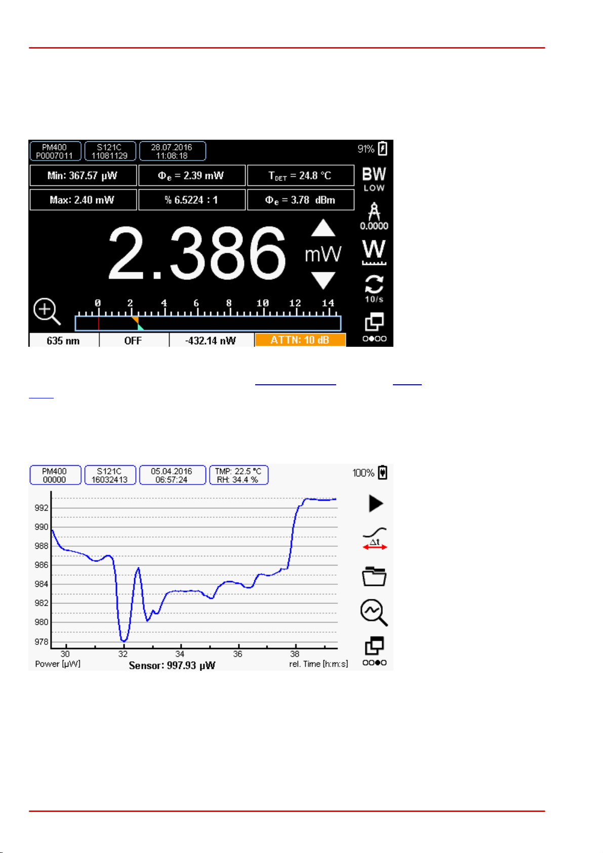
Numeric Display - Photodiode Sensor with External 10 dB Attenuator
Bandwidth Setting
Resolution of the digital
value
Toggle to change units
Display Update rate
Next Screen
Graph Display in Capturing Mode
Start / Stop Capturing
Show all results/
Roll latest
Open folder with captured
files
Analyze capture (Switch
to Viewer Mode)
Next Screen
Numerical Display
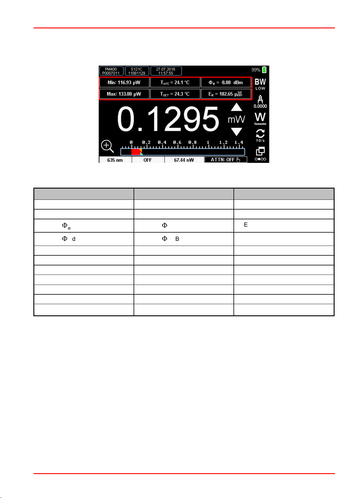
Numerical display with bar graph. This view has six additional small configurable displays with
additional, sensor specific information.
The sub-display configuration is accessible by drop down menus.
The lower display bar shows from left the set wavelength, status of Delta measurement and the
Zero compensation value.
Graph Display
The graph display allows to capture measurements over time and to analyze the results.
© 2017 Thorlabs GmbH18
Page 21
3 Operating Instruction
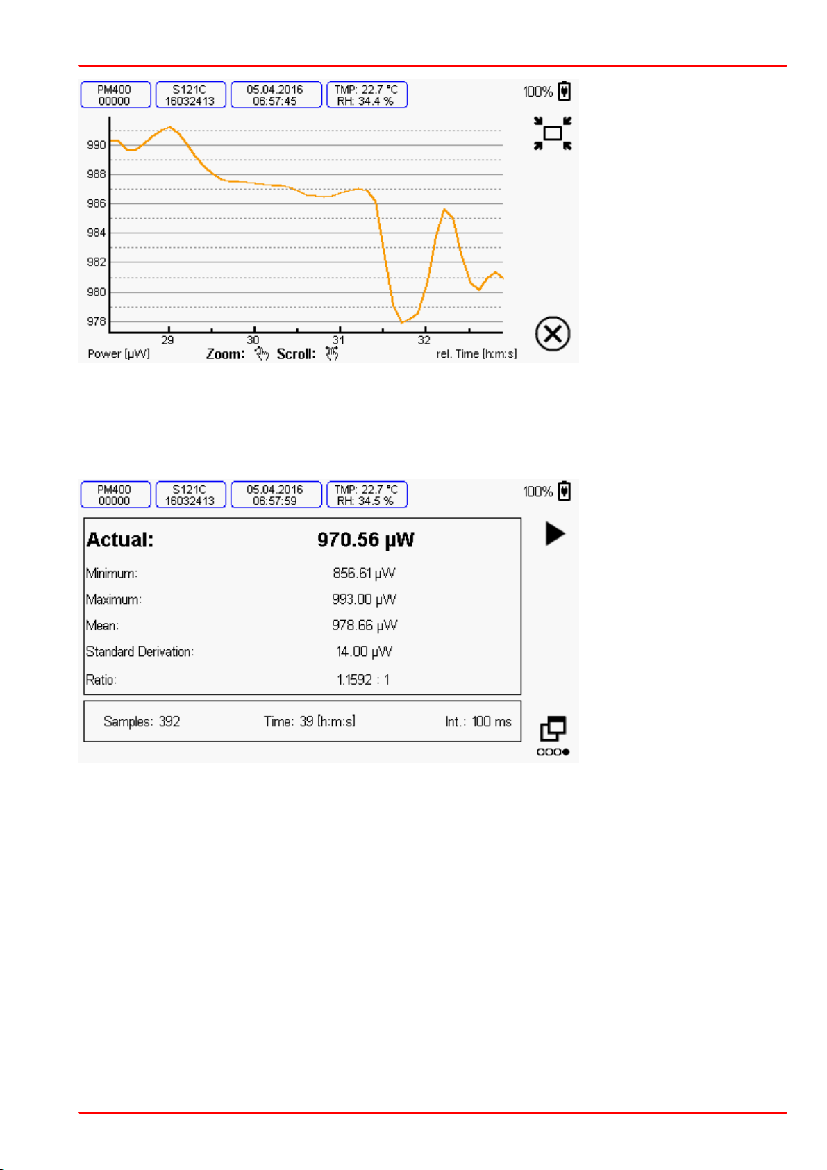
Graph Display in Viewer Mode
Zoom Home
Exit Viewer and Return
to Capture Mode
Statistics Display
Start / Stop Sampling
Next Screen
Statistics Display
In the Statistics Display a sequential measurement can be started. The display then shows typical statistic values over the expired time / samples.
© 2017 Thorlabs GmbH
19
Page 22
PM400
mW
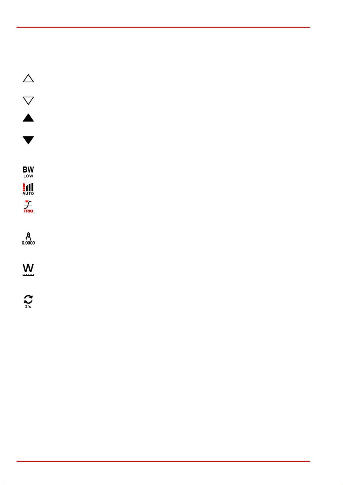
Tap on the measurement unit ("mW") to toggle between AUTO and MANUAL ranging.
When AUTO is enabled, the arrows are are shown in outlines.
mW
To switch from AUTO to manual, either tap on the measurement unit ("mW") or on one
of the arrows. When MANUAL is enabled, the arrows are are shown filled.
Depending on the detected sensor, the icon in the upper right corner allows to set specific features: Bandwidth setting (Photodiode sensors), Acceleration setting (Thermal
sensors) and Trigger level (Pyro-electric Energy sensors)
The Display Resolution can be set to 3, 4 or 5 significant digits.
Toggles between linear and logarithmic representation of the measurement results.
The Display Update Rate can be set to 10, 3 of 1 update per second.
3.2 Measurement Configuration
Ranging
The PM400 can be operated in AUTO and MANUAL ranging mode.
Sensor Specific Settings
Resolution of the Numeric Measurement Results
Measurement Units
Display Update Rate
© 2017 Thorlabs GmbH20
Page 23
3 Operating Instruction
3.3 Spectral Correction
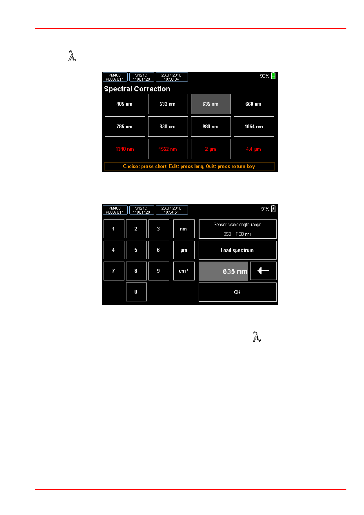
Press the button to enter the spectral correction menu.
This menu contains 12 entries, all of them are configurable. To edit an entry, press and hold it
for ~ 2 sec. The edit window comes up:
Now you can create an entry in either nanometers, micrometers or wavenumber or to load a
light spectrum curve in .csv format. Confirm and chose your entry
The actual wavelength setting value displays in the field above the button in Needle and Numerical measurement screens.
© 2017 Thorlabs GmbH
21
Page 24

PM400
3.4 Delta Mode
Press the button to enter the Delta Mode. The actual measurement value is set to zero,
saved as reference and the difference to the reference value. is displayed. The reference value
displays in the field above the operating button.
The scale-based indicators go to a middle setting.
3.5 Zeroing
Press the button to enter the Zeroing menu. Follow the displayed instructions.
After successful Zeroing, the Zero value is displayed in the field above the button in Need-
le and Numerical measurement screens.
© 2017 Thorlabs GmbH22
Page 25
3 Operating Instruction
3.6 Attenuation Correction
In order to take into account the attenuation of external devices (e.g. filter, beam splitter) to the
displayed measurement value, a correction factor can be assigned.
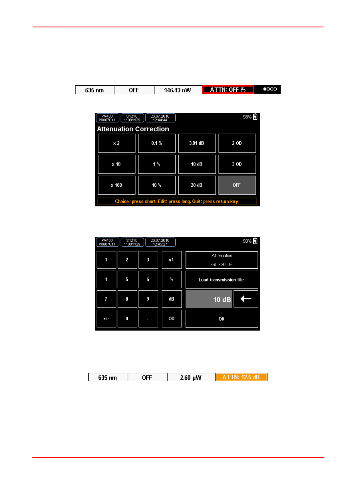
To enter the menu for the filter correction, press the ATTN button in the Numerical or Needle
screen:
A page with 12 free configurable presets comes up:
The attenuation can be assigned in "times" (e.g., "x2"), in percent, dB or in OD (optical density)
numbers. To edit an entry, press and hold it for ~2 seconds.
In this configuration window you can create an entry for an external filter etc. Further, there is
the possibility to load a complete filter transmission curve in .csv format. Press OK to confirm.
Then tap the edited entry to activate it. With active correction, the button displays in a different
color and shows the set value:
To disable the correction press and hold the ATTN button for 2 seconds, or chose an entry with
“OFF”.
© 2017 Thorlabs GmbH
23
Page 26
PM400
¢
Transmission curves of external filters (csv: wavelength, transmission)
¢
Translation files for language setting (UTF-8 w/o BOM: special format)
¢
Capturing files (csv: relative time, level)
¢
Screenshot images (bmp)
¢
Spectral curves of light sources (csv: wavelength, relative Intensity)
¢
Support document files and Software
3.7 Data Handling
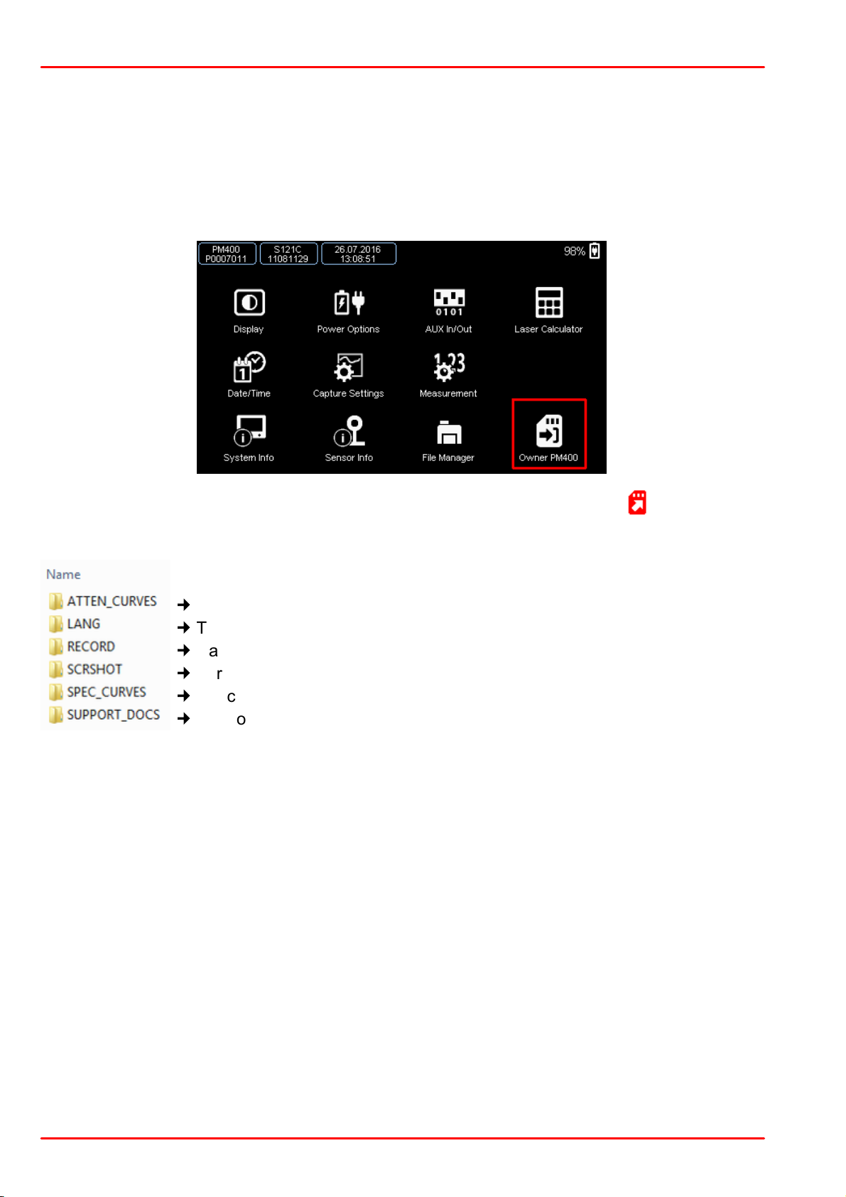
The PM400 has an internal 4 GB flash memory that holds captured measurement data, specific
correction, and language files. This internal memory is allocated by default to the system.
For accessing or modifying these data externally, and adding or removing files, the memory can
be mounted to a USB link to a PC. Therefore, call the system menu and tap the icon "Owner
PM400".
The icon changes to "Owner USB" and an additional red ‘memory card’ icon appears in the
header bar. The connected PC recognizes the PM400 memory as a "Removable Disk" that can
be accessed from the Windows explorer:
This memory also contains the device manuals, drivers and applications.
© 2017 Thorlabs GmbH24
Page 27
3 Operating Instruction
Photodiode Sensors
Thermal Sensors
Pyro-Electric Sensors
----- (none)
----- (none)
----- (none)
Current
Voltage
Voltage
Power
F
e
Power
F
e
Energy W
DET
Power
F
e
dBm
Power
F
e
dBm
(not available)
Max
Max
Max
Min
Min
Min
Ratio (Max/Min)
Ratio (Max/Min)
Ratio (Max/Min)
Sensor Temperature 1)
Sensor Temperature 1)
(not available)
Frequency
Frequency
Frequency
Ext. NTC Temperature
Ext. NTC Temperature
Ext. NTC Temperature
Irradiance E
e
Irradiance E
e
Fluence H
e
3.8 Subpanels
In the Numerical screen, 6 subpanels can be configured in order to display additional results:
To configure a subpanel, tap to it and select from the drop-down list the desired parameter.
Please note, that additional parameters are sensor-dependent, as stated in the table below:
1
) - Available only if a sensor-internal temperature sensor is detected.
© 2017 Thorlabs GmbH
25
Page 28
PM400
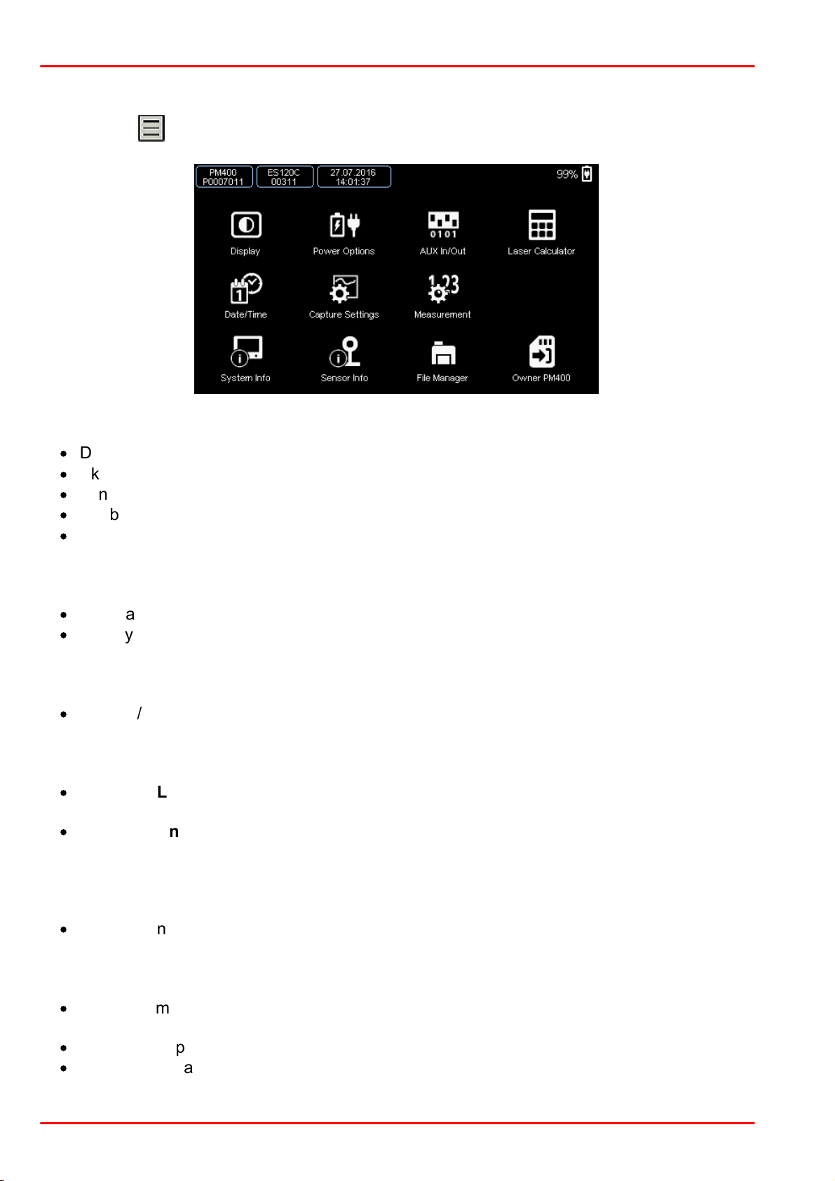
3.9 Main Menu
Pressing the button, opens the PM400 Main Menu.
Submenu Display
·
Display brightness
·
Skin (dark or light)
·
Language (English, German, Chinese or French)
·
Enable / disable button sound
·
Lock / unlock GUI control; in Remote operation: performs GTL (Go To Local) command
Submenu Power Options
·
Dim Backlight and Auto-Shutdown on battery and mains operation
·
Battery state information
Submenu AUX IN / Out
·
Enable / Disable GPIO ports
Submenu Laser Calculator
·
Submenu Laser Calculator: Allows entering beam parameters for correct calculation of
the additional parameters
·
Submenu Unit Converter: Allows optical power conversion between W and dBm, wavelength conversion between wavelength, frequency, wave numbers and photon energy.
Submenu Date / Time
·
Set date and time
Submenu Capture Settings
·
Set long-time capture parameters: capture control (manual, time, number of samples) and
capture interval (10 ms to 60 s)
·
Optional temperature logging
·
Returns estimated output file size
© 2017 Thorlabs GmbH26
Page 29

3 Operating Instruction
Submenu Measurement
·
Sensor-dependent content
·
Adjust common settings (mode, wavelength, attenuation, displayed measurement units,
ranging, display resolution and update rate, etc.)
·
Enter beam parameters (shape, type and diameter)
·
Adjust settings of the sensor-internal temperature sensor
·
Select type of custom sensor, if used
Submenu System Info
Submenu Sensor Info
Submenu File Manager
·
Manage files in the Flash memory
Button Memory Owner
·
Assign the Flash memory access between PM400 or a connected via USB PC
© 2017 Thorlabs GmbH
27
Page 30
PM400
3.10 Charging the Battery
The PM400 can be charged
·
by connecting it to a PC USB port. In this case, the internal charging circuit enters the "Slow
Charge" mode at a max. current of 500 mA, as it usually delivered by a PC Standard USB
port.
·
by connecting it to a wall-plug charger as it comes with smart phones, tablets etc. These
chargers have a so called "Dedicated Charging Port". In this case, the PM400 enters the
high current charging mode, with a maximum current of 1 A.
With a connected PC or charger, the Battery Charging Indicator displays the charging status:
·
Red: The battery is charging.
·
Green: The battery is fully charged. Remove the charger under environmental aspects.
·
Red blinking: The connected charger is not compatible with the Dedicated Charging Port
specification. The battery is charged only with a current of about 100 mA.
3.11 Analog and Auxiliary I/O
Analog Out
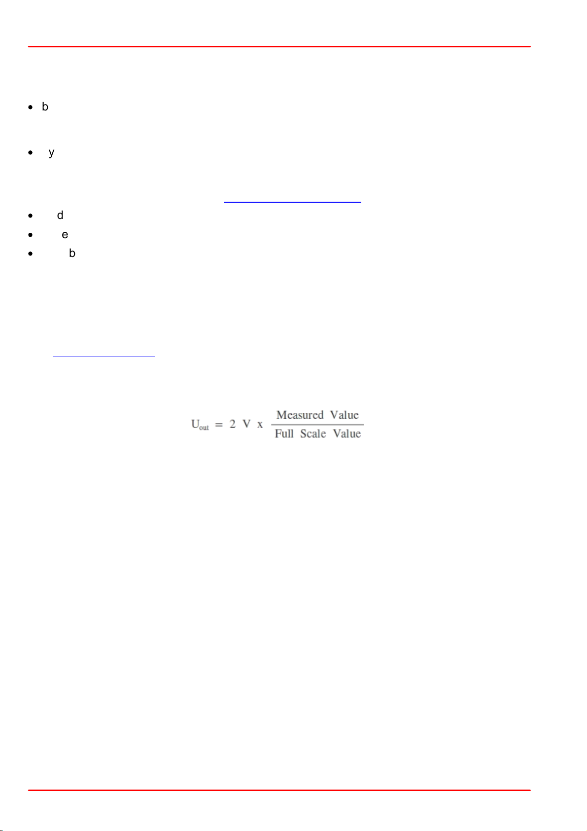
The Analog Output jack provides the amplified photo-diode current or the amplified thermal or
pyroelectric sensor voltage. The signals from the analog output are not wavelength- and zerocorrected. The analog output voltage can range from 0 to +2.0V. It is is measurement range dependent and can be calculated to:
Auxiliary I/O
This 14 pin connector in the top panel gives access to four configurable general purpose input/output (GPIO) pins and two 10bit ADC inputs.
With the optional available environmental module that can be plugged into this connector it is
possible to monitor the room temperature and the relative humidity.
© 2017 Thorlabs GmbH28
Page 31
4 Computer Interface
4 Computer Interface
The PM400 optical power meter contains a USB 2.0 interface for remote control of the unit by
an external PC. Connect the unit via the Mini-USB connector in the top panel to a free USB port
of your PC.
Prior to connect the PM400, make sure that at least the NI-VISA Runtime 5.4.1 is installed to
the computer. This software is available on the National Instruments website www.ni.com, and
included with with the PM400 software package as well.
When connecting the PM400 first time, a new hardware will be found.
4.1 PM400 Utility Software
The PM400 comes with an utility software that easily enables remote operation of the PM400 as well as othe Thorlabs GmbH Power Meters - along with visualizing and logging of measurement data. The PM400 utility software does not require the installation of the instrument drivers
as described in section Using the Instrument Drivers.
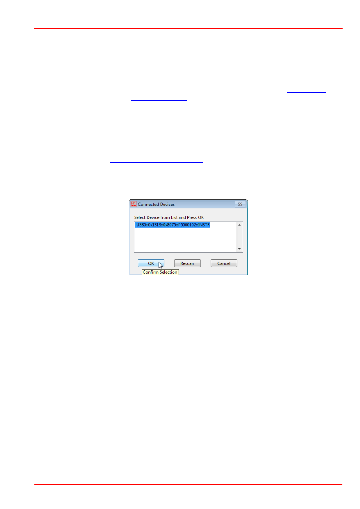
After launching the PM400 utility program it will automatically screen for connected console devices. Select the desired device and press o.k. In case that the connected console is not yet
recognized, press Rescan to perform a new search for connected devices.
The identification string contains the following items:
USB0 USB Port number
0x1313 Thorlabs Vendor ID
0x8075 Product ID = PM400
P5000102 Instrument serial number
INSTR Measurement instrument device
© 2017 Thorlabs GmbH
29
Page 32
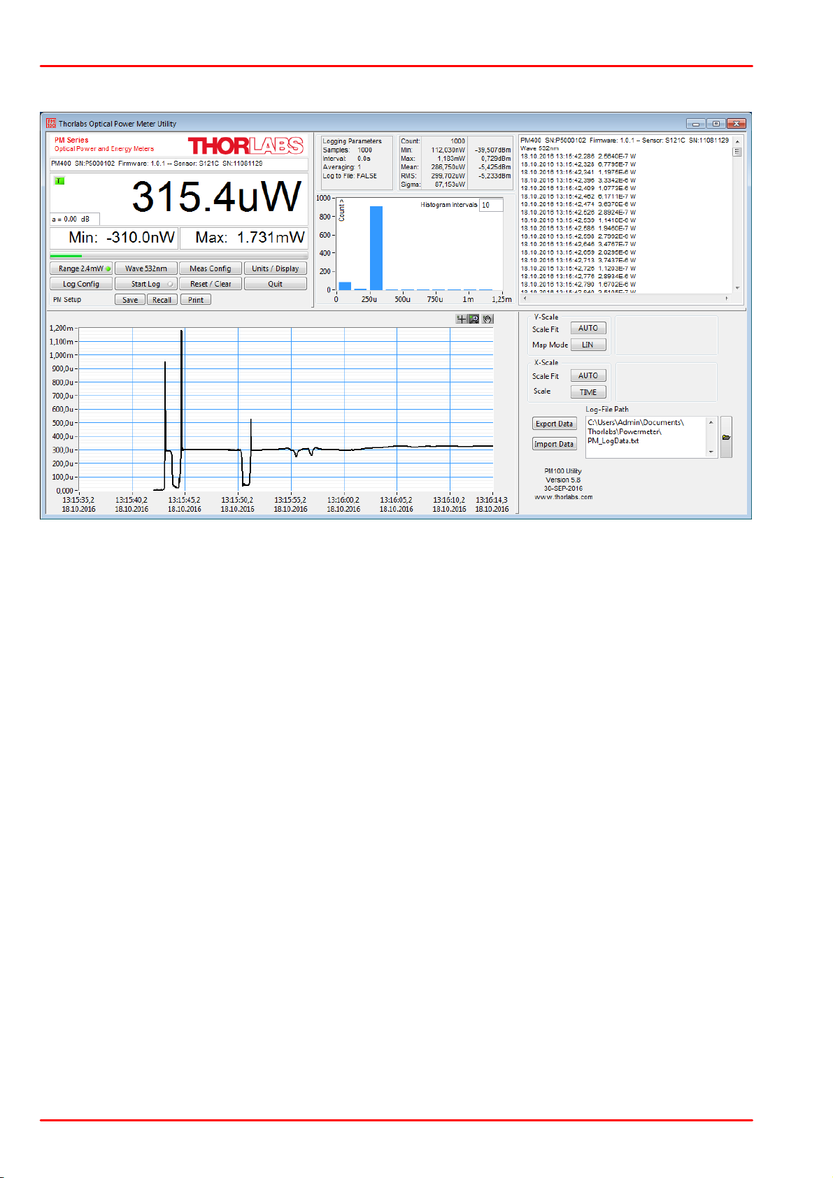
PM400
Header
This indicator shows the device setup:
- console type (PM400)
- serial number of the console
- sensor type
- sensor serial number
Main Display
The display has a configurable display resolution. Independent
from the measurement range the display always has the full number of the selected digits.
To achieve best AD converter resolution it is necessary to set the
measurement range according to the signal to measure.
A trigger indicator shows whether the unit is sampling data ‘A’ indicator or a new measurement value gets displayed ‘T’ indicator
and green light.
Left Sub Display
The display has the following configurable items:
- no display
- maximum value - sampling until reset
- ratio max/min value - sampling until reset
- power or energy density
- alternate unit depending on connected sensor
Available choices depend on the connected sensor
Right Sub Display
The display has the following configurable items, the possible
choices depend on the connected sensor:
- no display
- minimum value - sampling until reset
- frequency or repetition rate
- temperature
- resistance of temperature sensor
Front Panel
Description of the Front Panel Elements
© 2017 Thorlabs GmbH30
Page 33

4 Computer Interface
Bargraph indicator
The bargraph indicator shows the incidence or the used measurement range.
Statistics screen
Statistical values in linear and logarithmic representation
Data logging screen
Shows the logging history data
Histogram Power /
Energy Histogram
- displays histogram data
Chart Display
Power/Energy Chart
Range button
Press to open a dialog box for setting the measurement range.
The indicator in the button shows the currently used measurement
range in the chosen unit. A green light indicates 'auto-ranging'
Shortcut: [Shift + F1]
Wavelength /
Response button
Press this button to open a dialog box for setting the correction
wavelength, or in adapter mode to enter the responsivity value in
A/W or V/W. The currently used parameter is indicated in the button label.
Shortcut: [Shift + F2]
Measurement configuration
button
Depending on the connected sensor the following parameters can
be set in the dialog box:
- display resolution - set number of digits
- averaging rate, a rate of 3000 averages the incoming measurement values for approx. 1 second
- photodiode bandwidth HI and LO
- acceleration circuit for thermal sensors ON, AUTO and OFF
- trigger level for pyroelectric sensors
- Zeroing for photodiode and thermal sensors
Shortcut: [Shift + F3]
Units / Display button
A dialog box with the following items appears:
- configure unit of measure, depending on the connected sensor [W, J, dBm, V and A]
- configure the left sub display
- configure the right sub display
Shortcut: [Shift + F4]
Logging configuration button
- Opens a dialog box to:
- set averaging rate for logging
- set interval between samples
- set number of samples
- configure logging into data file
Shortcut: Shift + F5
Start/Stop log button
- start and stop data logging
Shortcut: [Shift + F6]
Reset / Clear button
- reset min/max monitor
- clear power / energy graph
- clear power / energy histogram
- clear power / energy statistics
- clear log screen
Shortcut: [Shift + F7]
Quit button
- stops the PM400 application
- to restart press the white arrow in the tool bar
Shortcut: [Shift + F8]
© 2017 Thorlabs GmbH
31
Page 34
PM400
Instrument Setup
Save / Recall
- save / recall remote control specific parameters
Shortcut: [Shift + F9]
Long Term Measurement
- sets the device to local mode between the measurement intervals
Shortcut: [Shift + F10]
4.2 Using the Instrument Drivers
Instrument Driver Installation
The PM400 software package contains a set of instrument drivers that allows conveniently remote controlling the instrument in most common programming languages. The instrument drivers must be installed, please follow the setup dialog instructions.
Note
To successfully complete the install of the PM400 USB driver you must have Administrator privileges on the PC which you are performing the install.
Prior to connecting the PM400 with a PC, please check if NI-VISA is installed on the PC, otherwise install NI-VISA that is available for free from the National Instruments website www.ni.com
or from the data carrier that came with the instrument.
After successfully installing the drivers connect the PM400 to a USB port of your PC. The PC
will find a PM400 test and measurement device. Please follow the instructions of the dialog
screens and allow the installing.
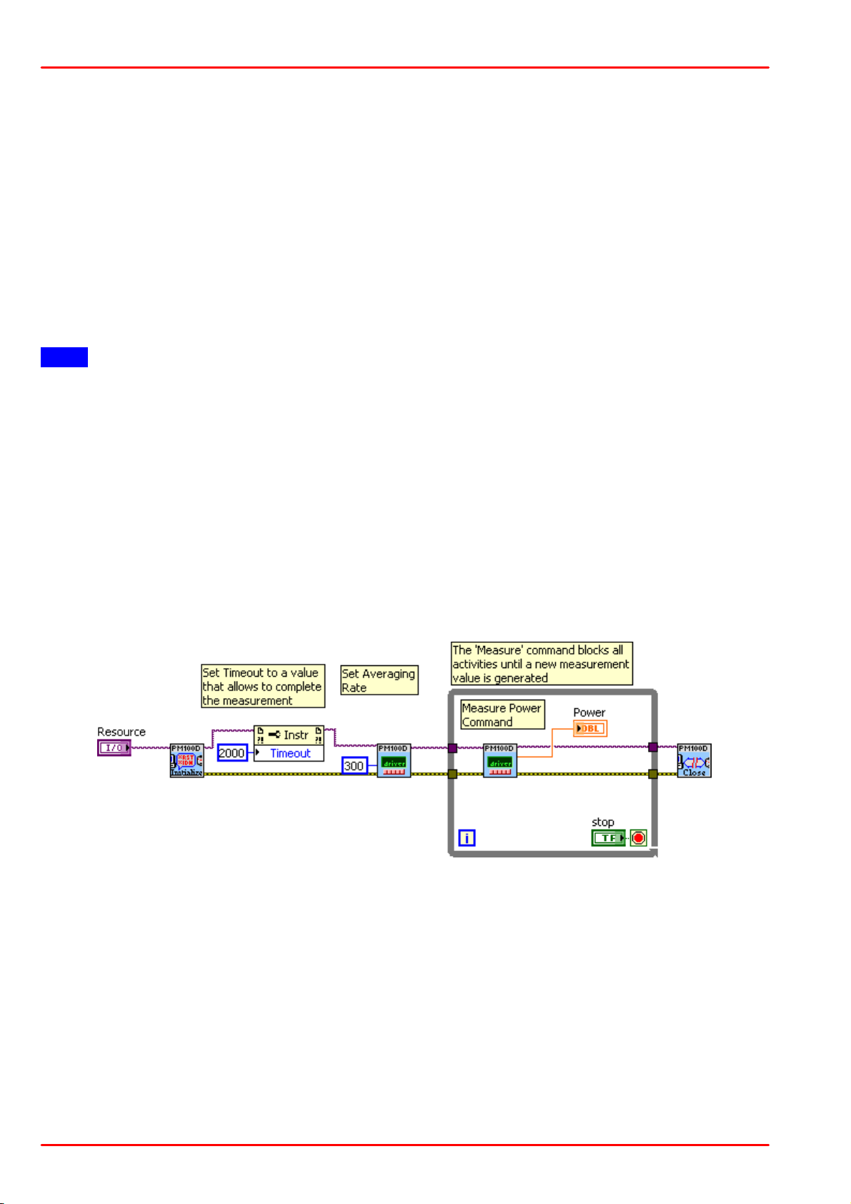
Instrument Driver Example
The following LabVIEW example demonstrates how to use the instrument drivers for measurement tasks. The example is included on the data carrier that came with the instrument.
© 2017 Thorlabs GmbH32
Page 35
5 Write Your Own Application
Programming environment
Necessary files
C, C++, CVI
*.fp (function panel file; CVI IDE only)
*.h (header file)
*.lib (static library)
*.dll (dynamic linked library)
C#
.net wrapper dll
Visual Studio
*.h (header file)
*.lib (static library)
or
.net wrapper dll
LabView
*.fp (function panel) and NI VISA instrument driver
Beside that, LabVIEW driver vi's are provided with the *.llb
container file
5 Write Your Own Application
In order to write your own application, you need a specific instrument driver and some tools for
use in different programming environments. The driver and tools are included in the installer
package and cannot be found as separate files on the installation CD.
In this section the location of drivers and files, required for programming in different environments, are given for installation under Windows XP (32 bit) and Windows 7 (32 and 64 bit)
Note
PM400 software and drivers contains 32 bit and 64 bit applications.
In 32 bit systems, only the 32 bit components are installed to
C:\Program Files\...
In 64 bit systems the 64 bit components are being installed to
C:\Program Files\...
while 32 bit components can be found at
C:\Program Files (x86)\...
In the table below you will find a summary of what files you need for particular programming environments.
Note
All above environments require also the NI VISA instrument driver dll !
During NI-VISA Runtime installation, a system environment variable VXIPNPPATH for including
files is created. It contains the information where the drivers are installed to, usually to C:
\Program Files\IVI Foundation\VISA\WinNT\.
This is the reason, why after installation of a NI-VISA Runtime a system reboot is required: This
environment variable is necessary for installation of the instrument driver software components.
In the next sections the location of above files is described in detail.
© 2017 Thorlabs GmbH
33
Page 36

PM400
5.1 Windows XP 32bit
NI VISA Instrument Driver 32bit
C:\Program Files\IVI Foundation\VISA\WinNT\Bin\PM100D_32.dll
Online Help for NI VISA Instrument Driver
C:\Program Files\IVI Foundation\VISA\WinNT\PM100D\Manual\PM100D.html
NI LabVIEW Driver
The LabVIEW version of this driver was generated with the "NI LabVIEW Instrument Driver Import Wizard 2.0" in conjunction with LabVIEW 2011.
C:\Program Files\IVI Foundation\VISA\WinNT\PM100D\LabVIEW\PM100D.llb
Header File
C:\Program Files\IVI Foundation\VISA\WinNT\include\PM100D.h
Static Library
C:\Program Files\IVI Foundation\VISA\WinNT\lib\msc\PM100D_32.lib
Function Panel
C:\Program Files\IVI Foundation\VISA\WinNT\PM100D\PM100D.fp
.net wrapper dll
C:\Program Files\IVI Foundation\VISA\VisaCom\...
...Primary Interop Assemblies\Thorlabs.PM100D.dll
C:\Program Files\IVI Foundation\VISA\WinNT\PM100D\DotNet\...
...Thorlabs.PM100D.dll
C:\Program Files\Microsoft.NET\Primary Interop Assemblies\...
...Thorlabs.PM100D.dll
Examples
ANSI-C
C:\Program Files\IVI Foundation\VISA\WinNT\PM100D\Samples\C\sample.c
Thorlabs PM100x/PM160/PM200 Instrument Driver Sample Application with console interface.
Read the comment text in the sample.c file for more information.
C# Visual Studio 2010
C:\Program Files\IVI Foundation\VISA\WinNT\PM100D\Samples\...
...DotNet\DotNetSample.csproj
Very basic C# sample project. The application opens a session to a device takes one measurement and closes the device again.
© 2017 Thorlabs GmbH34
Page 37

5 Write Your Own Application
5.2 Windows Vista / 7 / 8 - 32bit
NI VISA Instrument Driver
C:\Program Files\IVI Foundation\VISA\WinNT\Bin\PM100D_32.dll
Online Help for NI VISA Instrument Driver:
C:\Program Files\IVI Foundation\VISA\WinNT\PM100D\Manual\PM100D.html
NI LabVIEW Driver
The LabVIEW version of this driver was generated with the "NI LabVIEW Instrument Driver Import Wizard 2.0" in conjunction with LabVIEW 2011.
C:\Program Files\IVI Foundation\VISA\WinNT\PM100D\LabVIEW\PM100D.llb
Header File
C:\Program Files\IVI Foundation\VISA\WinNT\include\PM100D.h
Static Library
C:\Program Files\IVI Foundation\VISA\WinNT\lib\msc\PM100D_32.lib
Function Panel
C:\Program Files\IVI Foundation\VISA\WinNT\PM100D\PM100D.fp
.net wrapper dll
C:\Program Files\IVI Foundation\VISA\VisaCom\...
...Primary Interop Assemblies\Thorlabs.PM100D.dll
C:\Program Files\IVI Foundation\VISA\WinNT\PM100D\DotNet\...
...Thorlabs.PM100D.dll
C:\Program Files\Microsoft.NET\Primary Interop Assemblies\...
...Thorlabs.PM100D.dll
Examples:
ANSI-C
C:\Program Files\IVI Foundation\VISA\WinNT\PM100D\Samples\C\sample.c
Thorlabs PM100x/PM160/PM200 Driver Sample Application with console interface. Read the
comment text in the sample.c file for more information.
C# Visual Studio 2010
C:\Program Files\IVI Foundation\VISA\WinNT\PM100D\Samples\...
...DotNet\DotNetSample.csproj
Very basic C# sample project. The application opens a session to a device takes one measurement and closes the device again.
© 2017 Thorlabs GmbH
35
Page 38

PM400
5.3 Windows Vista / 7 / 8 - 64bit
NI VISA Instrument Driver 32bit
C:\Program Files (x86)\IVI Foundation\VISA\WinNT\Bin\PM100D_32.dll
NI VISA Instrument Driver 64bit
C:\Program Files\IVI Foundation\VISA\Win64\Bin\PM100D_64.dll
Online Help for NI VISA Instrument Driver
C:\Program Files\IVI Foundation\VISA\Win64\PM100D\Manual\PM100D.html
NI LabVIEW Driver 32bit
C:\Program Files (x86)\IVI Foundation\VISA\WinNT\PM100D\...
...LabVIEW\PM100D.llb
NI LabVIEW Driver 64bit
C:\Program Files\IVI Foundation\VISA\Win64\PM100D\LabVIEW\PM100D.llb
Header File 32bit
C:\Program Files (x86)\IVI Foundation\VISA\WinNT\include\PM100D.h
Header File 64bit
C:\Program Files\IVI Foundation\VISA\Win64\include\PM100D.h
Static Library 32bit
C:\Program Files (x86)\IVI Foundation\VISA\WinNT\lib\msc\PM100D_32.lib
Static Library 64bit
C:\Program Files\IVI Foundation\VISA\Win64\Lib_x64\msc\PM100D_64.lib
Function Panel 32bit
C:\Program Files (x86)\IVI Foundation\VISA\WinNT\PM100D\PM100D.fp
Function Panel 64bit
C:\Program Files\IVI Foundation\VISA\Win64\PM100D\PM100D.fp
© 2017 Thorlabs GmbH36
Page 39

5 Write Your Own Application
.net wrapper dll 32bit
C:\Program Files (x86)\IVI Foundation\VISA\VisaCom\...
...Primary Interop Assemblies\Thorlabs.PM100D.dll
C:\Program Files (x86)\Microsoft.NET\Primary Interop Assemblies\...
...Thorlabs.PM100D.dll
.net wrapper dll 64bit
C:\Program Files\IVI Foundation\VISA\VisaCom64\...
...Primary Interop Assemblies\Thorlabs.PM100D.dll
Examples:
ANSI-C
C:\Program Files\IVI Foundation\VISA\Win64\PM100D\Samples\C\sample.c
Thorlabs PM100x/PM160/PM200 Driver Sample Application with console interface. Read the
comment text in the sample.c file for more information.
C# Visual Studio 2010
C:\Program Files\IVI Foundation\VISA\Win64\PM100D\Samples\DotNet\...
...DotNetSample_64.csproj
Very basic C# sample project. The application opens a session to a device takes one measurement and closes the device again.
© 2017 Thorlabs GmbH
37
Page 40
PM400
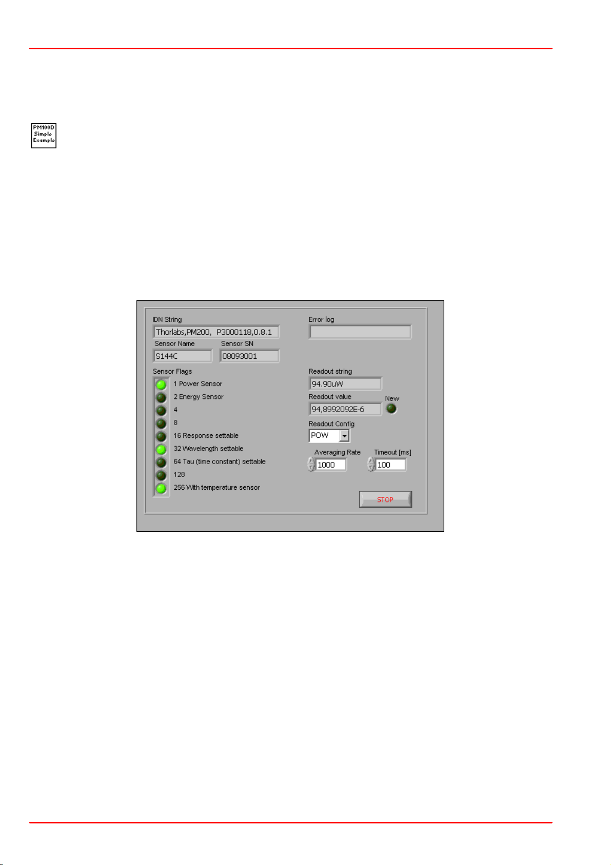
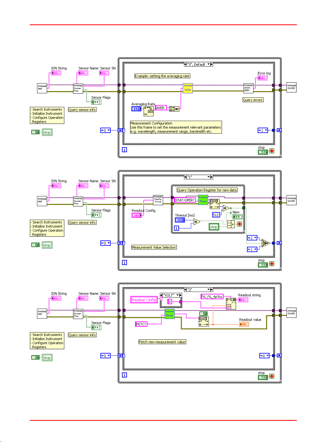
PM100D Simple Example.vi
This VI shows how to communicate with a PM400 optical power/energy meter with
SCPI commands. The following steps are demonstrated within this application:
- Initializing the instrument
- Getting system info
- Setting parameters
- Measurement configuration
- Measuring queue
- Fetching and displaying a measurement value
- Closing the application
5.4 Simple LabVIEW Example using SCPI commands
The PM400 Instrument driver is not required for this LabVIEW example.
© 2017 Thorlabs GmbH38
Page 41
Block Diagram
5 Write Your Own Application
© 2017 Thorlabs GmbH
39
Page 42
PM400
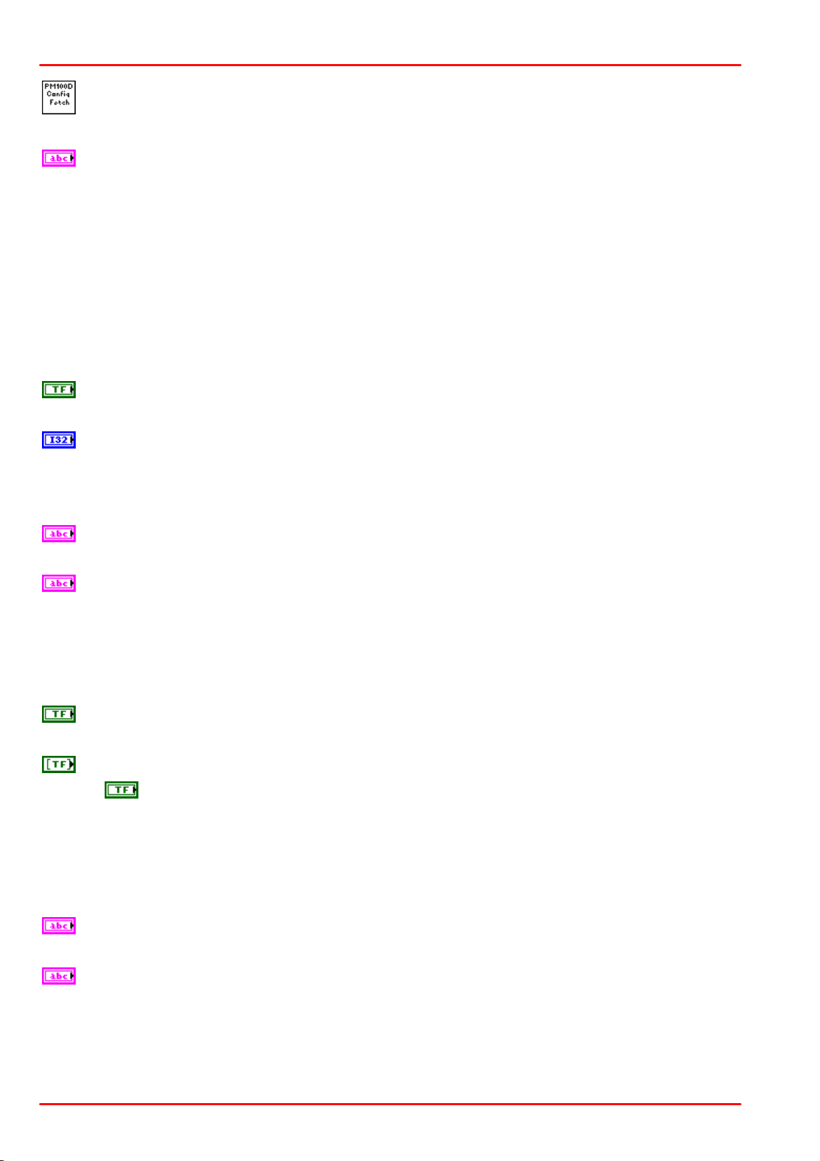
Averaging Rate
Sets the averaging rate - 3000 averages take approximately 1s for performing a new
measurement value
Readout Config
Selects the measurement parameter
- POW power measurement in W
- CURR current measurement in A
- VOLT voltage measurement in V
- ENER energy measurement in J
- FREQ frequency / repetition rate measurement in Hz
- PDEN power density measurement in W/cm²
- EDEN energy density measurement in J/cm²
- RES thermistor resistance measurement in Ohm
- TEMP temperature measurement in °C
Stop
Stops application
Timeout [ms]
Sets a timeout value in ms that allows the instrument to sample.
The timeout must be longer than it takes to perform a new measurement. This has
especially to be considered when performing single shot energy measurements.
Error log
Error indicator, 'no error' is suppressed
Readout string
Formatted measurement value
- limitation to 4 significant digits
- SI notation
- '.' decimal separator
- appended unit according readout configuration
New
Indicator lights up, when a new measurement value is processed
Sensor Flags
Sensor flag bitmap:
1 Is power sensor
2 Is energy sensor
16 Response settable
32 Wavelength settable
64 Tau settable
256 Has temperature sensor
Sensor Name
Name of connected power/energy sensor
Sensor SN
Serial number of connected power/energy sensor
© 2017 Thorlabs GmbH40
Page 43
5 Write Your Own Application
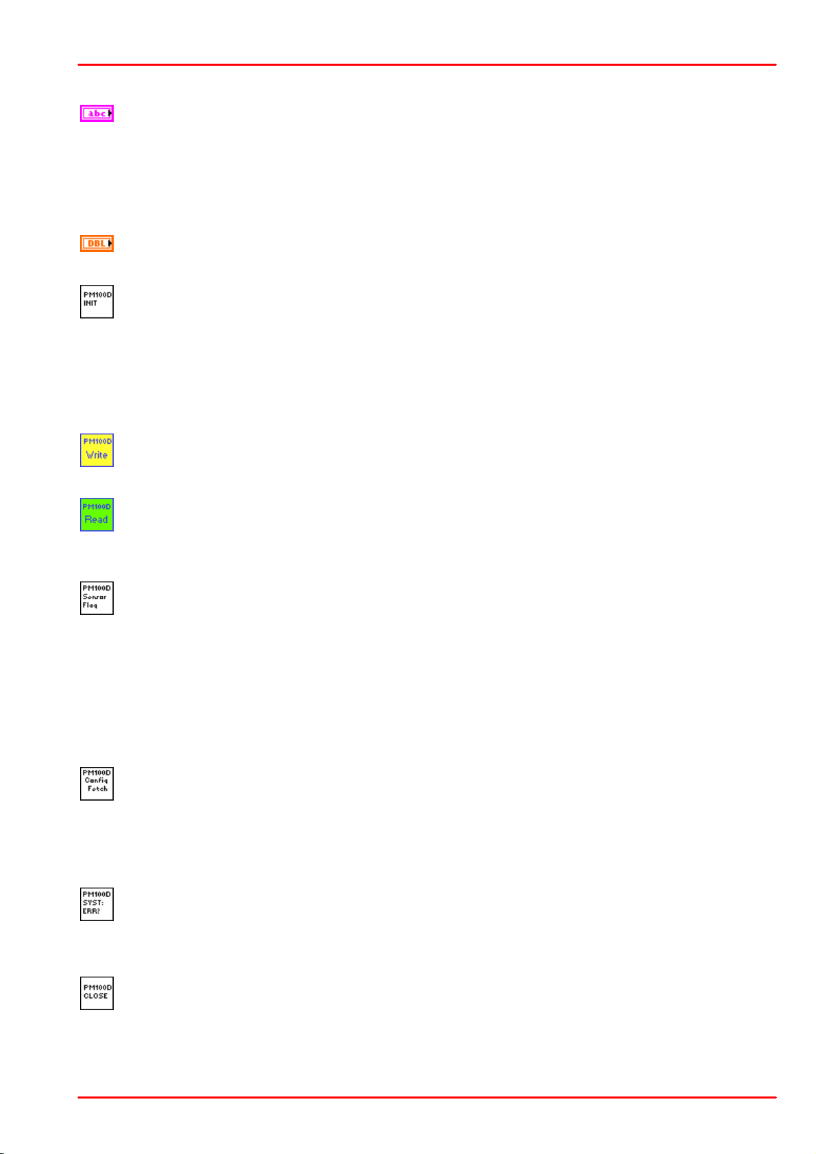
IDN String
Answer from instrument on *idn? command:
- manufacturer
- model number
- serial number
- firmware version
Readout value
Plain readout value in full resolution
PM100D_Initialize.vi
This VI scans for connected devices, that can be selected in a dialog box. Next steps
- setting timeout
- performing identification query
- configuring the operation register to '512'; flag gets to HI when a new measure-
ment value is ready to fetch
- clear operation register
PM100D_Write.vi
Writes a SCPI command to the connected instrument
PM100D_Read.vi
Reads data from the connected instrument. All query commands according the SCPI
command table are terminated by a question mark (?)
PM100D_SensorFlag.vi
This VI queries all relevant sensor info with SYST:SENS:IDN?
- sensor name
- sensor serial number
- calibration message
- sensor type
- sensor sub-type
- sensor flags
PM100D_ConfMeas.vi
- CONFigure measurement; CONF:<parameter> (POW, ENER, etc.)
- ABORt measurement
- Clear operation register with STAT:OPER?
- INITiate measurement
PM100D_SYST-ERR.vi
This VI lists all errors coming from the instrument with the command SYST:ERR?
'no error' is suppressed
PM100D_Close.vi
Closes the VISA session
Sets the connected instrument in local mode (default option)
© 2017 Thorlabs GmbH
41
Page 44

PM400
5.5 SCPI Commands
This section describes in detail the SCPI command set with respect to PM400 power meter
console. However, these commands are compatible with PM100A, PM100D and PM100USB
consoles as well as with the PM160 Hand-held Power Meter, except some console and sensor
related functions.
5.5.1 An Introduction to the SCPI language
The PM400 interface commands use the SCPI (Standard Commands for Programmable Instruments), an ASCII-based command language that was designed for test and measurement instruments.
SCPI commands are based on a hierarchical structure, also known as a tree system. In this
system, associated commands are grouped together under a common node or root, thus forming subsystems. A portion of the SENSE subsystem is shown below to illustrate the tree system.
SENSe:
CORRection
:COLLect
:ZERO
[:INITiate]
:ABORt
:STATe?
:MAGNitude?
:BEAMdiameter {MINimum|MAXimum|DEFault|<numeric_value>[mm]}
:BEAMdiameter? [{MINimum|MAXimum|DEFault}]
:WAVelength {MINimum|MAXimum|<numeric_value>[nm]}
:WAVelength? [{MINimum|MAXimum}]
:POWer
[:PDIode]
[:RESPonse] MINimum|MAXimum|DEFault|<numeric_value>[A]}
[:RESPonse]? [{MINimum|MAXimum|DEFault}]
:THERmopile
[:RESPonse] {MINimum|MAXimum|DEFault|<numeric_value>[V]}
[:RESPonse]? [{MINimum|MAXimum|DEFault}]
SENSe is the root keyword of the command, CORRection is the second-level keyword, and
COLLect and BEAMdiameter are third-level keywords, and so on.
A colon ( : ) separates a command keyword from a lower-level keyword.
Command Format
The format used to show commands in this manual is shown below:
CURRent[:DC]:RANGe {MINimum|MAXimum|<numeric_value>[A]}
CORRection:BEAMdiameter {MINimum|MAXimum|DEFault|<numeric_value>[mm]}
The command syntax shows most commands (and some parameters) as a mixture of upperand lower-case letters. The upper-case letters indicate the abbreviated spelling for the com-
mand. For shorter program lines, send the abbreviated form. For better program readability,
send the long form.
For example, in the above syntax statement, CURR and CURRENT are both acceptable forms.
You can use upper- or lower-case letters. Therefore, CURRENT, current and Current are
all acceptable. Other forms, such as CUR and CURREN, will generate an error.
© 2017 Thorlabs GmbH42
Page 45

5 Write Your Own Application
Braces ( { } ) enclose the parameter choices for a given command string. The braces are not
sent with the command string. A vertical bar ( | ) separates multiple parameter choices for a given command string.
Triangle brackets ( < > ) indicate that you must specify a value for the enclosed parameter. For
example, the above syntax statement shows the range parameter enclosed in triangle brackets.
The brackets are not sent with the command string. You must specify a value for the parameter
(such as "CURR:DC:RANG 50E-6").
Some parameters are enclosed in square brackets ( [ ] ). The brackets indicate that the
parameter is optional and can be omitted. The brackets are not sent with the command string.
In this example [:DC] can be omitted, so the command string can be shortened to
“CURR:RANG 50E-6”. If you do not specify a value for an optional parameter, the power/energy meter chooses a default value.
Command Separators
A colon ( : ) is used to separate a command keyword from a lower-level keyword. You must insert a blank space to separate a parameter from a command keyword. If a command requires
more than one parameter, you must separate adjacent parameters using a comma as shown
below:
"SYST:TIME 10, 34, 48"
A semicolon ( ; ) is used to separate commands within the same subsystem, and can also minimize typing. For example, sending the following command string:
"CORR:BEAM 1; WAV 1310"
... is the same as sending the following two commands:
"CORR:BEAM 1"
"CORR:WAV 1310"
Use a colon and a semicolon to link commands from different subsystems. For example, in the
following command string, an error is generated if you do not use both the colon and semicolon:
"CORR:BEAM 1;:AVER 300"
Using the MIN and MAX Parameters
You can substitute MINimum or MAXimum in place of a parameter for many commands. For ex-
ample, consider the following command:
CURRent[:DC]:RANGe {MINimum|MAXimum|<numeric_value>[A]}
Instead of selecting a specific current range, you can substitute MIN to set the range to its minimum value or MAX to set the range to its maximum value.
Querying Parameter Settings
You can query the current value of most parameters by adding a question mark (?) to the command. For example, the following command sets the operating wavelength to 1550 nm:
"CORR:WAV 1550"
You can query the operating wavelength by executing: "CORR:WAV?". You can also query the
minimum or maximum operating wavelength allowed as follows:
"CORR:WAV? MIN"
"CORR:WAV? MAX"
Caution
If you send two query commands without reading the response from the first, and then attempt
to read the second response, you may receive some data from the first response followed by
the complete second response. To avoid this, do not send a query command without reading
© 2017 Thorlabs GmbH
43
Page 46

PM400
the response. When you cannot avoid this situation, send a device clear before sending the second query command.
SCPI Command Terminators
A command string sent to the power/energy meter must terminate with a <new line> character.
The IEEE-488 EOI (end-or-identify) message is interpreted as a <new line> character and can
be used to terminate a command string in place of a <new line> character. A <carriage return>
followed by a <new line> is also accepted. Command string termination will always reset the
current SCPI command path to the root level.
IEEE488.2 Common Commands
The IEEE-488.2 standard defines a set of common commands that perform functions like reset,
self-test, and status operations. Common commands always begin with an asterisk (*), are four
to five characters in length, and may include one or more parameters. The command keyword
is separated from the first parameter by a blank space. Use a semicolon (;) to separate multiple commands as shown below:
"*RST; *CLS; *ESE 32; *OPC?"
SCPI Parameter Types
The SCPI language defines several different data formats to be used in program messages
and response messages.
Numeric Parameters Commands that require numeric parameters will accept all commonly
used decimal representations of numbers including optional signs, decimal points, and scientific
notation.
Special values for numeric parameters like MINimum, MAXimum and DEFault are also accepted. You can also send engineering unit suffixes with numeric parameters (e.g., M,K, or u).
If only specific numeric values are accepted, the power/energy meter will automatically round
the input numeric parameters. The following command uses a numeric parameter:
POWer:REFerence {MINimum|MAXimum|DEFault|<numeric_value>[W]}
Discrete Parameters Discrete parameters are used to program settings that have a limited
number of values (like W,DBM). They can have a short form and a long form just like command
keywords. You can mix upper- and lower-case letters. Query responses will always return the
short form in all upper-case letters. The following command uses discrete parameters:
POW:UNIT {W|DBM}
Boolean Parameters Boolean parameters represent a single binary condition that is either true
or false. For a false condition, the power/energy meter will accept “OFF” or “0”. For a true condition, the meter will accept “ON” or “1”. When you query a boolean setting, the instrument will
always return “0” or “1”. The following command uses a boolean parameter:
CURRent:RANGe:AUTO {OFF|0|ON|1}
String Parameters String parameters can contain virtually any set of ASCII characters. A string
must begin and end with matching quotes; either with a single quote or with a double quote.
You can include the quote delimiter as part of the string by typing it twice without any characters in between. The following command uses a string parameter:
DIAG:CALString <quoted string>
© 2017 Thorlabs GmbH44
Page 47
5 Write Your Own Application
Mnemonic
Name
Description
*CLS
Clear status
Clears all event registers and Error Queue
*ESE
<NRf>
Event enable command
Program the Standard Event Enable Register
*ESE?
Event enable query
Read the Standard Event Enable Register
*ESR?
Event status register query
Read and clear the Standard Event Register
*IDN?
Identification query
Read the unit’s identification string
*OPC
Operation complete command
Set the Operation Complete bit in the Standard Event Register
*OPC?
Operation complete query
Places a “1” into the output queue when all
device operations have been completed
*RST
Reset command
Returns the unit to the *RST default condition
*SRE
<NRf>
Service request enable command
Programs the Service Request Enable Register
*SRE?
Service request enable query
Reads the Service Request Enable Register
*STB?
Status byte query
Reads the Status Byte Register
*TST?
Self-test query
Performs the unit’s self-test and returns the result.
*WAI
Wait-to-continue command
Wait until all previous commands are executed
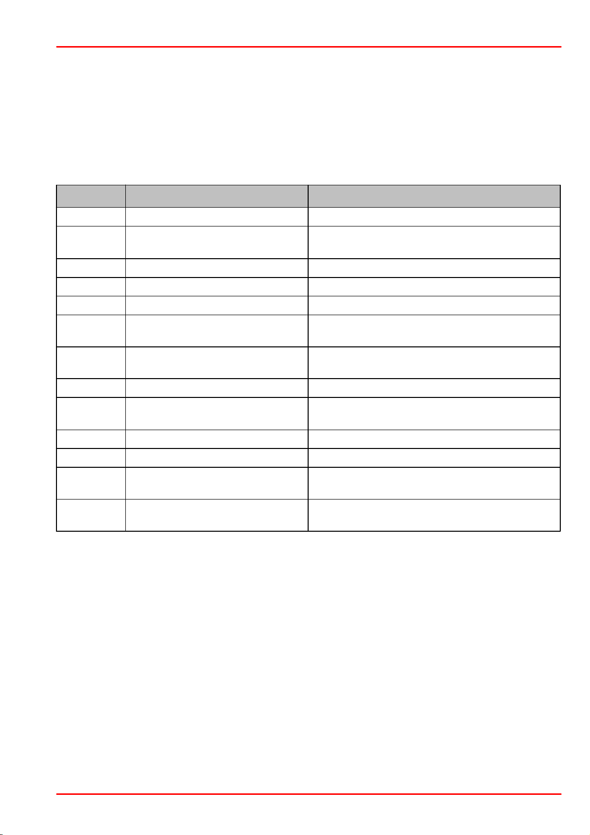
5.5.2 IEEE488.2 Common Commands
Common commands are device commands that are common to all devices according to the
IEEE488.2 standard. These commands are designed and defined by this standard. Most of the
commands are described in detail in this section. The following common commands associated
with the status structure are covered in the “Status Structure” section: *CLS, *ESE, *ESE?,
*ESR?, *SRE, *SRE?, *STB?
5.5.2.1 Command Summary
© 2017 Thorlabs GmbH
45
Page 48

PM400
5.5.2.2 Command Reference *IDN? – identification query - read identification code
The identification code includes the manufacturer, model code, serial number, and firmware revision levels and is sent in the following format: THORLABS,MMM,SSS,X.X.X
Where: MMM is the model code
SSS is the serial number
X.X.X is the instrument firmware revision level
*OPC – operation complete - set OPC bit
*OPC? – operation complete query – places a “1” in output queue
When *OPC is sent, the OPC bit in the Standard Event Register will set after all pending command operations are complete. When *OPC? is sent, an ASCII “1” is placed in the Output
Queue after all pending command operations are complete.
Typically, either one of these commands is sent after the INITiate command. The INITiate command is used to take the instrument out of idle in order to perform measurements. While operating within the trigger model layers, many sent commands will not execute. After all programmed operations are completed, the instrument returns to the idle state at which time all pending
commands (including *OPC and/or *OPC?) are executed. After the last pending command is
executed, the OPC bit and/or an ASCII “1” is placed in the Output Queue.
When *OPC is sent, the OPC bit in the Standard Event Register will set after all pending command operations are complete. When *OPC? is sent, an ASCII “1” is placed in the Output
Queue after all pending command operations are complete.
*RST – reset – return instrument to defaults
When the *RST command is sent, the instrument performs the following operations:
·
Returns the instrument to the default conditions
·
Cancels all pending commands.
·
Cancels response to any previously received *OPC and *OPC? commands.
*TST? – self-test query – run self test and read result
Use this query command to perform the instrument self-test routine. The command places the
coded result in the Output Queue. A returned value of zero (0) indicates that the test passed,
other values indicate that the test failed.
*WAI – wait-to-continue – wait until previous commands are completed
The *WAI command is a no operation command for the instrument and thus, does not need to
be used. It is there for conformance to IEEE488.2.
© 2017 Thorlabs GmbH46
Page 49
5 Write Your Own Application
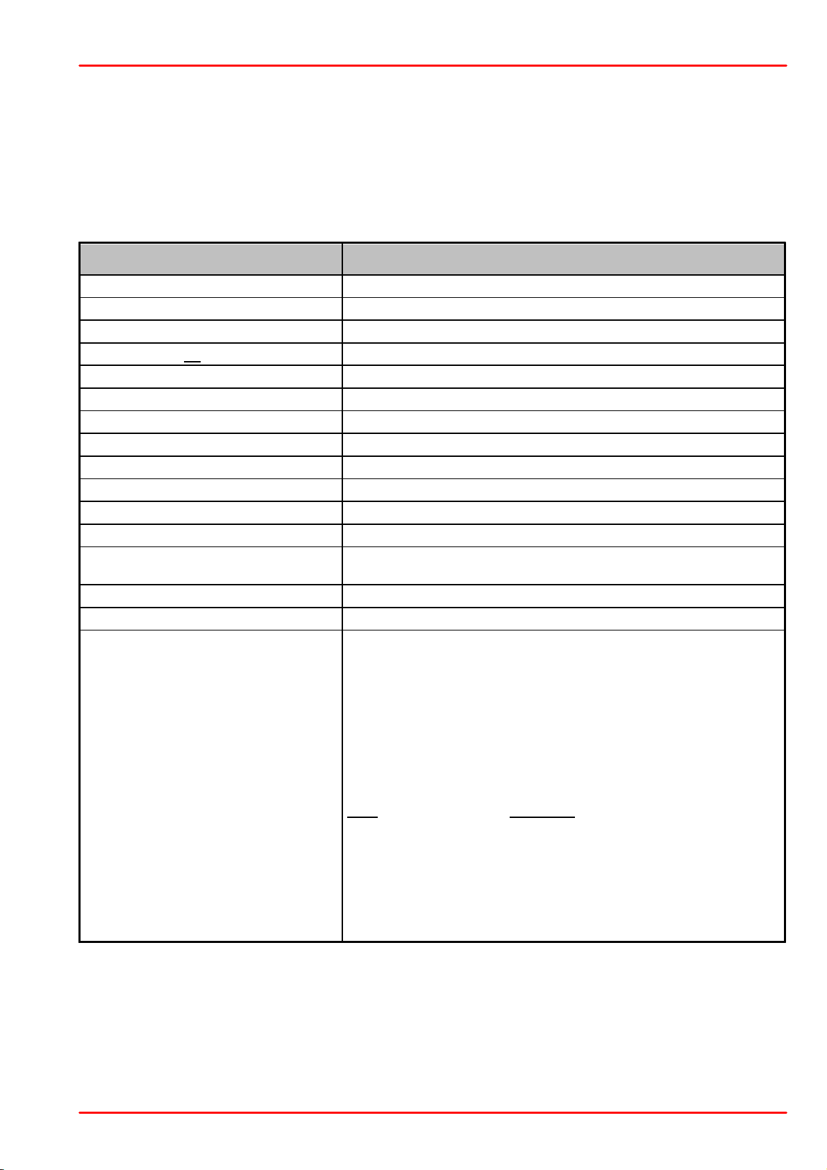
Command
Description
SYSTem
Path to SYSTem subsystem. (SCPI Vol.2 §21)
:BEEPer
[:IMMediate]
Issue an audible signal. (SCPI Vol.2 §21.2.2)
:STATe {ON|1|OFF|0}
Activate/deactivate the beeper. (SCPI Vol.2 §21.2.3)
:STATe?
Return the state of the the beeper (SCPI Vol.2 §21.2.3)
:ERRor
[:NEXT]?
Returns the latest <error code, “message”>. (SCPI Vol.2 §21.8.8)
:VERSion?
Query level of SCPI standard (1999.0) . (SCPI Vol.2 §21.21)
:DATE <year>,<month>,<day>
Sets the instrument’s calendar. (SCPI Vol.2 §21.7)
:DATE?
Query the instrument’s calendar. (SCPI Vol.2 §21.7)
:TIME <hour>,<min>,<sec>
Sets the instrument’s clock. (SCPI Vol.2 §21.19)
:TIME?
Query the instrument’s clock. (SCPI Vol.2 §21.19)
:LFRequency <numeric value>
Sets the instrument’s line frequency setting to 50 or 60Hz. (SCPI Vol.2
§21.13)
:LFRequency?
Query the instrument’s line frequency setting. (SCPI Vol.2 §21.13)
:SENSor
:IDN?
Query information about the connected sensor. This is a query only
command. The response consists of the following fields:
<name>,<sn>,<cal_msg>,<type>,<subtype>,<flags>
<name> Sensor name in string response format
<sn> Sensor serial number in string response format
<cal_msg> calibration message in string response format
<type> Sensor type in NR1 format
<subtype> Sensor subtype in NR1 format
<flags> Sensor flags as bitmap in NR1 format.
Flag:
Dec.value:
Is power sensor
1
Is energy sensor
2
Response settable
16
Wavelength settable
32
Tau settable
64
Has temperature sensor
256
5.5.2.3 PM400 specific SCPI Command Reference
See also SCPI Specification, Version 1999.0, May, 1999, http://www.scpiconsortium.org . All
commands with a ’SCPI’ checkmark are described in the SCPI specification.
All described commands work also with the PM100D, PM100A, PM100USB and PM160 instruments (with some limitations due to the hardware capabilities).
5.5.2.3.1 SYSTem subsystem commands
© 2017 Thorlabs GmbH
47
Page 50

PM400
Command
Description
STATus
Path to STATus subsystem. (SCPI Vol.2 §20)
:MEASurement
Path to control measurement event registers
[:EVENt]?
Read the event register
:CONDition?
Read the condition register
:PTRansition <value>
Program the positive transition filter
:PTRansition?
Read the positive transition filter
:NTRansition <value>
Program the negative transition filter
:NTRansition?
Read the negative transition filter
:ENABle <value>
Program the enable register
:ENABle?
Read the enable register
:AUXiliary
Path to control measurement event registers
[:EVENt]?
Read the event register
:CONDition?
Read the condition register
:PTRansition <value>
Program the positive transition filter
:PTRansition?
Read the positive transition filter
:NTRansition <value>
Program the negative transition filter
:NTRansition?
Read the negative transition filter
:ENABle <value>
Program the enable register
:ENABle?
Read the enable register
:OPERation
Path to control operation event registers
[:EVENt]?
Read the event register
:CONDition?
Read the condition register
:PTRansition <value>
Program the positive transition filter
:PTRansition?
Read the positive transition filter
:NTRansition <value>
Program the negative transition filter
:NTRansition?
Read the negative transition filter
:ENABle <value>
Program the enable register
:ENABle?
Read the enable register
:QUEStionable
Path to control questionable event registers
[:EVENt]?
Read the event register
:CONDition?
Read the condition register
:PTRansition <value>
Program the positive transition filter
:PTRansition?
Read the positive transition filter
:NTRansition <value>
Program the negative transition filter
:NTRansition?
Read the negative transition filter
:ENABle <value>
Program the enable register
:ENABle?
Read the enable register
:PRESet
Return status registers to default states.
5.5.2.3.2 STATus subsystem commands
© 2017 Thorlabs GmbH48
Page 51
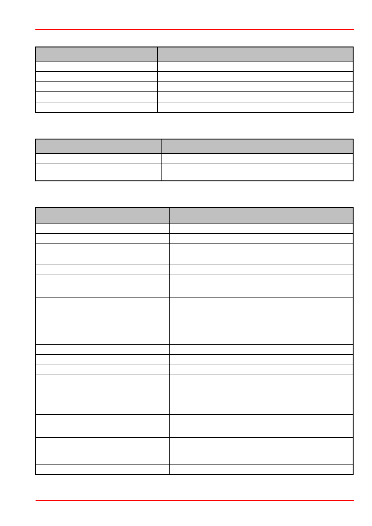
5.5.2.3.3 DISPlay subsystem commands
Command
Description
DISPlay
Path to DISPlay subsystem. (SCPI Vol.2 §8)
:BRIGhtness <value>
Set the display birghtness. (SCPI Vol.2 §8.2)
:BRIGhtness?
Return the display birghtness value. (SCPI Vol.2 §8.2)
:CONTrast <value>
Set the display contrast. (SCPI Vol.2 §8.4)
:CONTrast?
Return the display conrast value. (SCPI Vol.2 §8.4)
Command
Description
CALibration
Path to CALibration subsystem. (SCPI Vol.2 §5)
:STRing?
Returns a human readable calibration string. This is a query only
command. The response is formatted as string response data.
Command
Description
SENSe
Path to SENSe subsystem. (SCPI Vol.2 §18)
AVERage
[:COUNt] <value
Sets the averaging rate (1 sample takes approx. 3ms)
[:COUNt]?
Queries the averaging rate
CORRection
[:LOSS[:INPut[:MAGNitude]]]
{MINimum|MAXimum|DEFault|
<numeric_value>}
Sets a user attenuation factor in dB
[:LOSS[:INPut[:MAGNitude]]]?
[{MINimum|MAXimum|DEFault}]
Queries the user attenuation factor
COLLect
ZERO
[:INITiate]
Performs zero adjustment routine
ABORt
Aborts zero adjustment routine
STATe?
Queries the zero adjustment routine state
MAGNitude?
Queries the zero value
BEAMdiameter {MINimum|
MAXimum|DEFault|
<numeric_value>[mm]}
Sets the beam diameter in mm
BEAMdiameter? [{MINimum|
MAXimum|DEFault}]
Queries the beam diameter
WAVelength {MINimum|
MAXimum|
<numeric_value>[nm]}
Sets the operation wavelength in nm
WAVelength? [{MINimum|
MAXimum}]
Queries the operation wavelength
POWer
[:PDIOde]
Sets the photodiode response value in A/W
5.5.2.3.4 CALibration subsystem commands
5.5.2.3.5 SENSe subsystem commands
5 Write Your Own Application
© 2017 Thorlabs GmbH
49
Page 52

PM400
Command
Description
[:RESPonse] {MINimum|
MAXimum|DEFault|
<numeric_value>[A]}
[:RESPonse]?
[{MINimum|MAXimum|
DEFault}]
Queries the photodiode response value
:THERmopile
[:RESPonse] {MINimum|
MAXimum|DEFault|
<numeric_value>[V]}
Sets the thermopile response value in V/W
[:RESPonse]?
[{MINimum|MAXimum|
DEFault}]
Queries the thermopile response value
ENERgy
[:PYRO]
[:RESPonse] {MINimum|
MAXimum|DEFault|
<numeric_value>[V]}
Sets the pyro-detector response value in V/J
[:RESPonse]?
[{MINimum|MAXimum|
DEFault}]
Queries the pyro-detectro response value
CURRent[:DC]
RANGe
AUTO {OFF|0|ON|1}
Switches the auto-ranging function on and off
AUTO?
Queries the auto-ranging function state
[:UPPer] {MINmum|MAXimum|
<numeric_valuje>[A]}
Sets the current range in A
[:UPPer]? [{MINimum|
MAXimum}]
Queries the current range
REFerence {MINimum|
MAXimum|DEFault|
<numeric_value>[A]}
Sets a delta reference value in A
REFerence? [{MINimum|
MAXimum|DEFault}]
Queries the delta reference value
STATe {OFF|0|ON|1}
Switches to delta mode
STATe?
Queries the delta mode state
ENERgy
RANGe
[:UPPer] {MINmum|MAXimum|
<numeric_valuje>[J]}
Sets the energy range in J
[:UPPer]? [{MINimum|
MAXimum}]
Queries the energy range
REFerence {MINimum|
MAXimum|DEFault|
<numeric_value>[J]}
Sets a delta reference value in J
REFerence? [{MINimum|
MAXimum|DEFault}]
Queries the delta reference value
STATe {OFF|0|ON|1}
Switches to delta mode
STATe?
Queries the delta mode state
FREQuency
Range
© 2017 Thorlabs GmbH50
Page 53
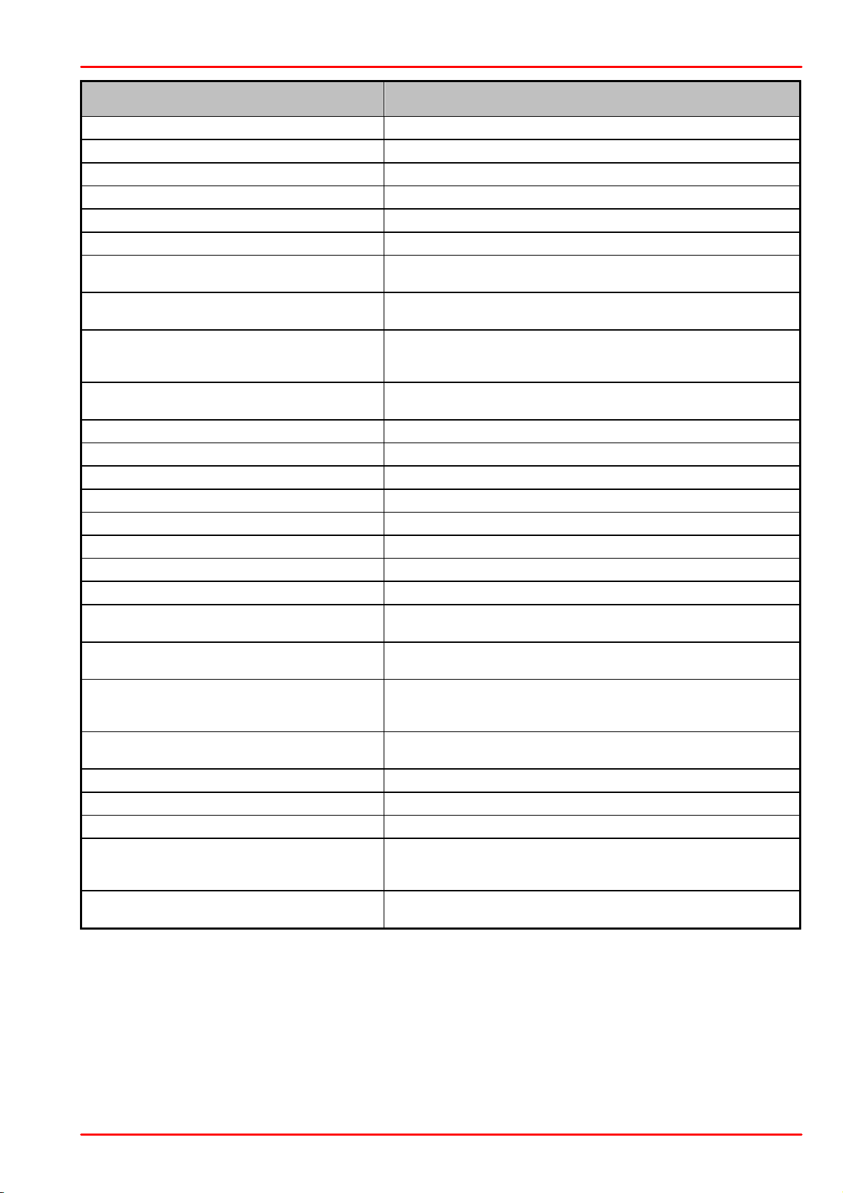
5 Write Your Own Application
Command
Description
[UPPer]?
Queries the frequency range
LOWer?
POWer[:DC]
RANGe
AUTO {OFF|0|ON|1}
Switches the auto-ranging function on and off
AUTO?
Queries the auto-ranging function state
[:UPPer] {MINmum|MAXimum|
<numeric_valuje>[W]}
Sets the power range in W
[:UPPer]? [{MINimum|
MAXimum}]
Queries the power range
REFerence {MINimum|
MAXimum|DEFault|
<numeric_value>[W]}
Sets a delta reference value in W
REFerence? [{MINimum|
MAXimum|DEFault}]
Queries the delta reference value
STATe {OFF|0|ON|1}
Switches to delta mode
STATe?
Queries the delta mode state
UNIT {W|DBM}
Sets the power unit W or dBm
UNIT?
Queries the power unit
VOLTage[:DC]
RANGe
AUTO {OFF|0|ON|1}
Switches the auto-ranging function on and off
AUTO?
Queries the auto-ranging function state
[:UPPer] {MINmum|MAXimum|
<numeric_valuje>[V]}
Sets the current range in V
[:UPPer]? [{MINimum|
MAXimum}]
Queries the current range
REFerence {MINimum|
MAXimum|DEFault|
<numeric_value>[V]}
Sets a delta reference value in V
REFerence? [{MINimum|
MAXimum|DEFault}]
Queries the delta reference value
STATe {OFF|0|ON|1}
Switches to delta mode
STATe?
Queries the delta mode state
PEAKdetector
[:THReshold] {MINimum|
MAXimum|DEFault|
<numeric_value>
Sets the trigger level in % for the energy mode
[:THReshold]? [{MINimum|
MAXimum|DEFault}
Queries the trigger level setting
© 2017 Thorlabs GmbH
51
Page 54
PM400
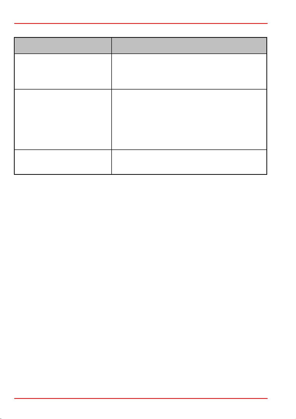
Command
Description
INPut
[:PDIode]
:FILTer
[:LPASs]
[STATe] {OFF|0|ON|1}
[STATe]?
Sets the bandwidth of the photodiode input stage
Queries the bandwidth of the photodiode inut stage
:THERmopile
:ACCelerator
[STATe] {OFF|0|ON|1}
[STATe]?
:AUTO {OFF|0|ON|1}
?
:TAU {MINimum|
MAXimum|DEFault|
<numeric_value>[s]}
:TAU? [{MINimum|
MAXimum|DEFault}]
Sets the thermopile accelerator state
Queries the thermopile accelerator state
Sets the thermopile accelerator to auto mode
Queries thermopile accelerator auto mode
Sets thermopile time constant 0-63% in s
Queries the thermopile time constant in s
:ADAPter
[:TYPE] {PHOTodiode|
THERmal|PYRo}
[:TYPE]?
Sets default sensor adapter type
Queries default sensor adapter type
5.5.2.3.6 INPut subsystem commands
© 2017 Thorlabs GmbH52
Page 55

5.5.2.3.7 Measurement commands
Command
Description
INITiate[:IMMediate]
Start measurement
ABORt
Abort measurement
CONFigure[:SCALar]
[:POWer]
Configure for power measurement
:CURRent[:DC]
Configure for current measurement
:VOLTage[:DC]
Configure for voltage measurement
:ENERgy
Configure for energy measurement
:FREQuency
Configure for frequency measurement
:PDENsity
Configure for power density measurement
:EDENsity
Configure for energy density measurement
:RESistance
Configure for sensor presence resistance measurement
:TEMPerature
Configure for sensor temperature measurement
MEASure[:SCALar]
[:POWer]
Performs a power measurement
:CURRent[:DC]
Performs a current measurement
:VOLTage[:DC]
Performs a voltage measurement
:ENERgy
Performs a energy measurement
:FREQuency
Performs a frequency measurement
:PDENsity
Performs a power density measurement
:EDENsity
Performs a energy density measurement
:RESistance
Performs a sensor presence resistance measurement
:TEMPerature
Performs a sensor temperature measurement
FETCh?
Read last measurement data (SCPI Vol.2 §3.2)
READ?
Start new measurement and read data (SCPI Vol.2 §3.3)
CONFigure?
Query the current measurement configuration.
5 Write Your Own Application
© 2017 Thorlabs GmbH
53
Page 56
PM400
6 Maintenance and Service
Protect the PM400 from adverse weather conditions. The PM400 is not water resistant.
Attention
To avoid damage to the instrument, do not expose it to spray, liquids or solvents!
The unit does not need a regular maintenance by the user. It does not contain any modules
and/or components that could be repaired by the user himself. If a malfunction occurs, please
contact Thorlabs GmbH for return instructions.
Also, please contact Thorlabs GmbH for replacement of the rechargeable battery:
Do not remove covers!
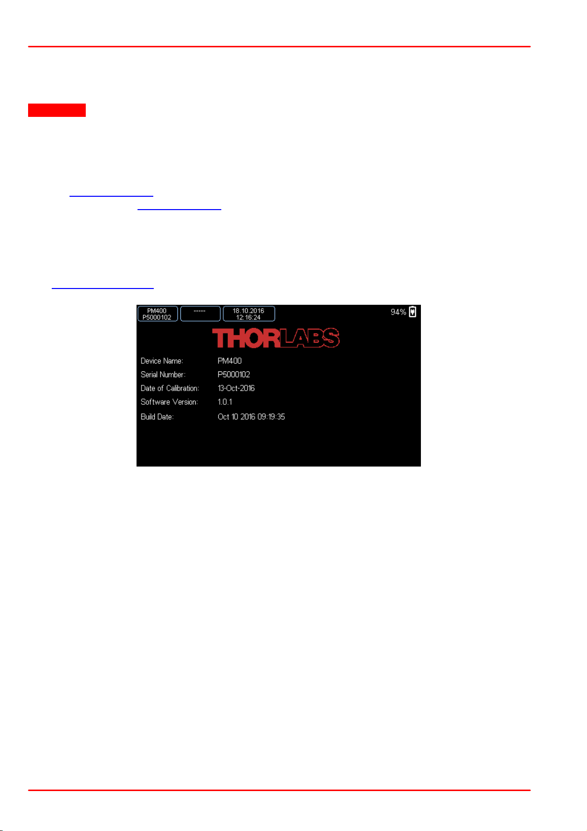
6.1 Version Information
The System Info screen of the PM400 shows important information:
© 2017 Thorlabs GmbH54
Page 57
7 Appendix
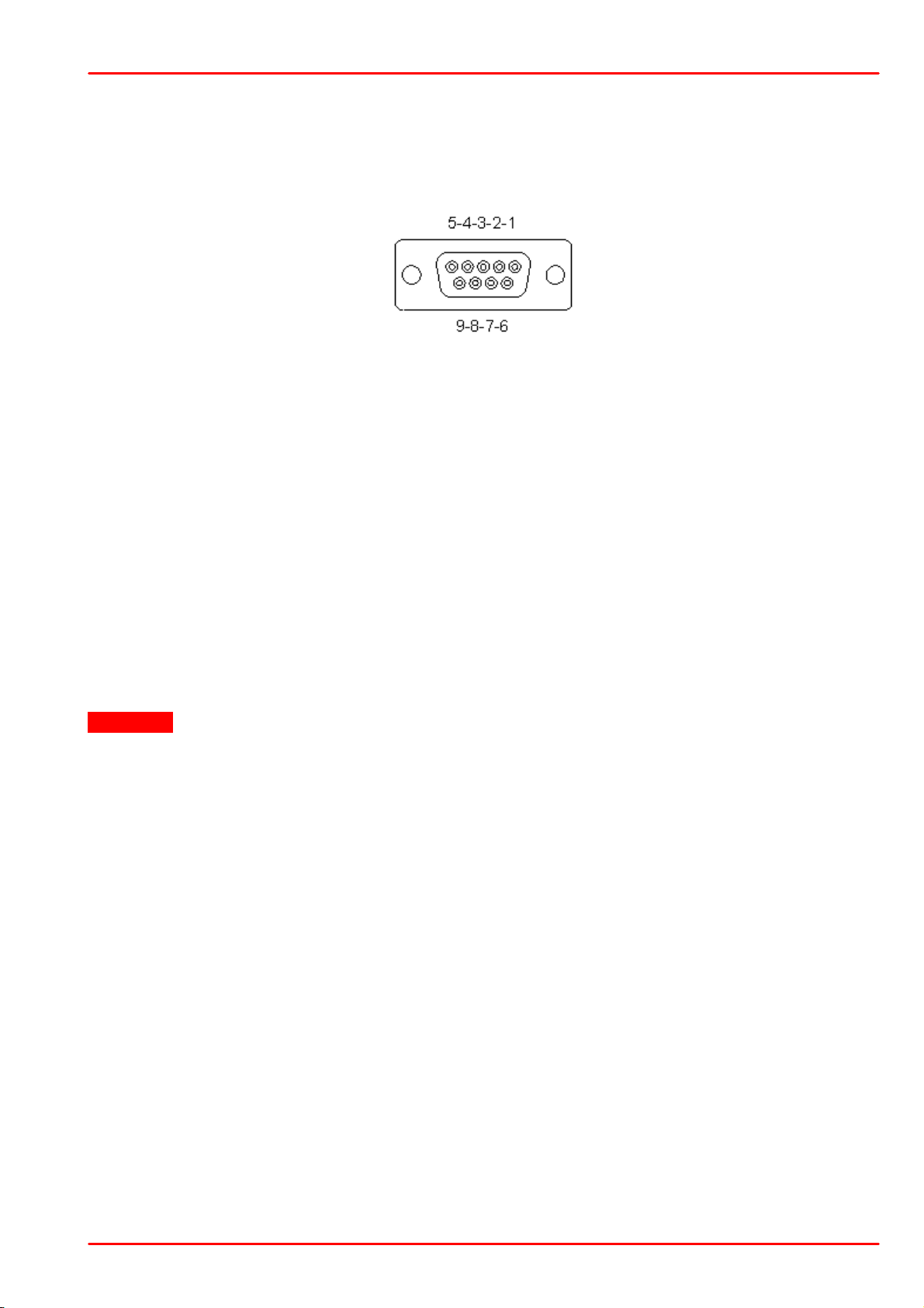
Pin-out of the 9pin DSUB
sensor connector (female)
7 Appendix
7.1 Sensor Connector Pinning
The PM400 is capable to support custom made detectors. Please read carefully the following
instruction prior to connecting a self made sensor.
Pin Connection
3 AGND (analog ground): photodiode ground (anode), thermal and pyro sensor
ground
4 photodiode cathode
5 pyroelectric sensor +
8 thermal sensor +
7 PRESENT: Connect this pin via a 1kΩ – 10kΩ resistor to pin 3 (AGND) to ena-
ble a custom sensor
1 +5V (max. current 100 mA from this pin)
6 DGND (digital ground)
9 n.c.
Warning
Pin 2 is uniquely used for the EEPROM Digital I/O (memory in Thorlabs sensor heads) and
MUST NOT be used. Connecting this pin may cause malfunction of the PM400.
© 2017 Thorlabs GmbH
55
Page 58
PM400
Features
Detector Compatibility
Photodiode Sensors S100C Series
Thermal Sensors S300C Series
Pyroelectric Sensors ES100C/ES200C Series
Photodiodes (Max 5 mA)
Thermopiles (Max 1 V)
Pyroelectric detectors (Max 100 V)
Display Type
4.3" TFT, WQVGA, 400 x 272 Pixels, 16 bit Color
Viewing Area
95 mm x 54 mm
Display Update Rate (max)
10 Hz Numerical, 25 Hz Analog Simulation
Display Format
Numerical, Bargraph, Trendgraph, Statistics, Simulated Analog
Needle
Backlight Display
LED, Adjustable
Features
Capacitive Touchscreen and Buttons, Support Stand, Rubberized
Outside,
2 x M3 Thread Inserts for Mounting on Back Side
Current Input (Photodiode Sensors)
Connector
DB9F
Units
W, dBm, W/cm², A
Measurement Ranges
6 Decades; 50 nA - 5 mA
Ranges Selectable in W, Sensor Dependent
Display Resolution
1 pA / Responsivity Value (A/W)
AD Converter
16 bit
Accuracy
±0.2% f.s. (5 µA - 5 mA)
±0.5% f.s. (50 nA)
Bandwidth
DC - 100 kHz, Dependent on Sensor and Settings
Wavelength Correction
nm (A/W)
Beam Area Setting
Diameter 1/e² or Rectangular x,y
Voltage Input (Thermopile Sensors)
Connector
DB9F
Units
W, dBm, W/cm², V
Measurement Ranges
9 Ranges: 2, 4, 10, 20, 40, 100, 200, 400, 1000 mV
Ranges Selectable in W, Sensor Dependent
Display Resolution
1 µV / Responsivity Value (V/W)
AD Converter
16 bit
Accuracy
±0.5% f.s. (10 mV - 1 V)
±1% f.s. (2mV)
Bandwidth
DC - 10 Hz, Dependent on Sensor and Settings
Time Constant Correction Range
1 s - 30 s
Wavelength Correction
Sensor Dependent; nm, (V/W)
Beam Area Setting
Diameter 1/e² or Rectangular x,y
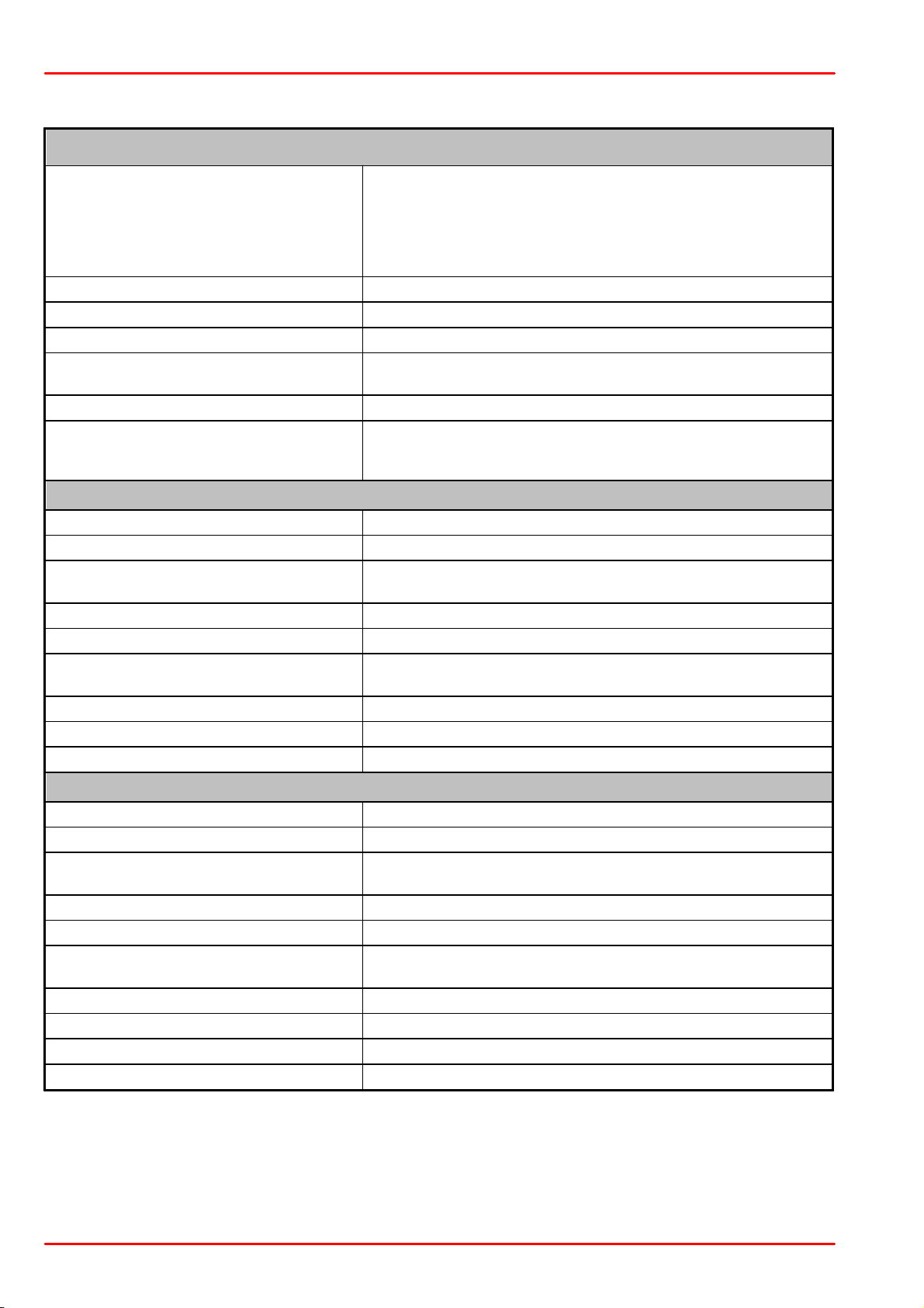
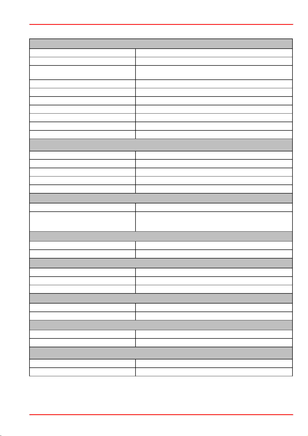
7.2 Technical Data
© 2017 Thorlabs GmbH56
Page 59
7 Appendix
Voltage Input (Pyro Sensors)
Connector
DB9F
Units
J, J/cm², W, W/cm², V
Measurement Ranges
4 Ranges: 200 mV - 2V - 20 V - 100 V
Ranges Selectable in J, Sensor Dependent
Display Resolution
100 µV / Responsivity Value (V/J)
AD Converter
16 bit
Accuracy
± 0.5% f.s.
Trigger Threshold
3% - 90% f.s.
Max. Repetition Rate
3 kHz
Wavelength Correction
Sensor Dependent [nm, V/J]
Beam Area Setting
Diameter 1/e² or Rectangular x,y
Analog Output
Connector
2p Audio 3.5 mm (Adapter to BNC included)
Signal
Amplified Input Signal - Not Corrected
Voltage Range
0 to 2 V
Accuracy
±3%
Bandwidth
up to 100 kHz, Dependent on Sensor and Settings
Auxiliary In-/Output
Connector
2 x 7 Pins, 0.1" Socket, Top Side
Function
4 x GPIO
2 x 10 bit ADC for external temperature, rel. humidity sensor
+3.3 V, +/- 2.5 V (100 mA max.)
Temperature Sensor Internal to C-Series Optical Sensors
Supported Temperature Sensor
Thermistor
Temperature Measurement Range
-10 °C to +80 °C
External Temperature Sensor
Supported Temperature Sensor
Thermistor NTC 0.1 – 100 kΩ, B-Value 1000 – 9999 K
Temperature Measurement Range
-10 °C to +80 °C (w. TSP-TH)
Connector
3P Audio 2.5 mm
Sound
Type
Speaker
Function
Laser Tuning Support, Console Function Support
Memory
Type
Nand Flash
Size
4 GB
Interfaces
Type
USB2.0
Connector
Mini-B USB
© 2017 Thorlabs GmbH
57
Page 60
PM400
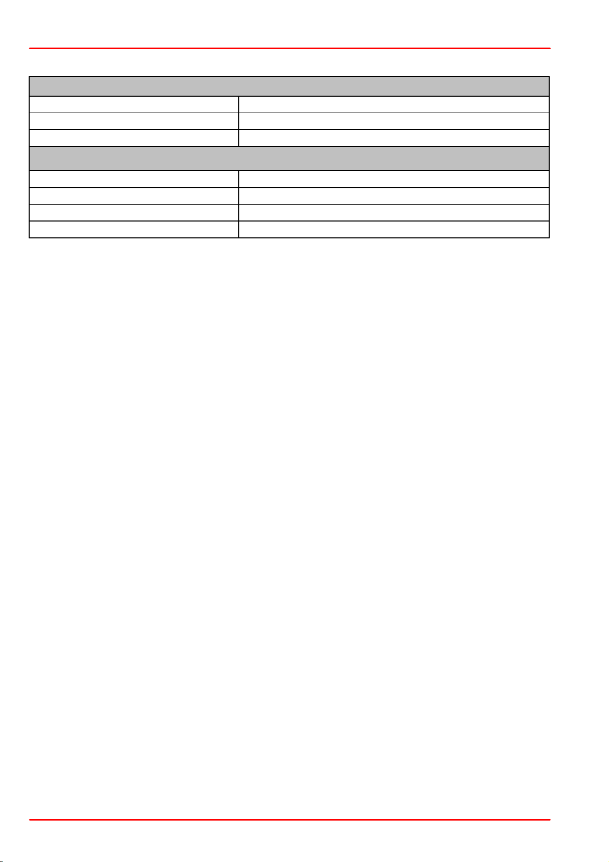
Power Management
Battery
LiPo 3.7 V 2600 mAh
Charger
Built in; Charging Current: 0.5 / 1 A
Power Connector
Mini USB
General
Operating Temperature Range 1)
0 to 40 °C
Storage Temperature Range
-40 to 70 °C
Dimensions (W x H x D)
136 mm x 96 mm x 29 mm
Weight
0.35 kg
1
) non-condensing
All technical data are valid at 23 ± 5°C and 45 ± 15% rel. humidity (non condensing)
© 2017 Thorlabs GmbH58
Page 61
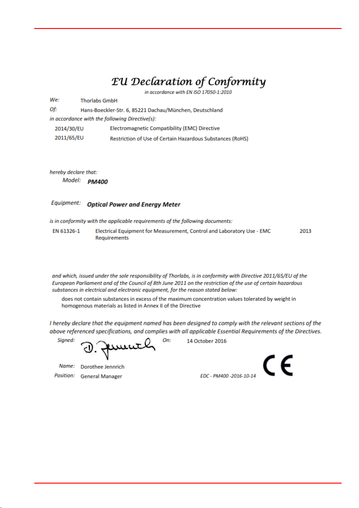
7.3 Certifications and Compliances
7 Appendix
© 2017 Thorlabs GmbH
59
Page 62
PM400
Symbol
Units
Description
F
e
W (J/s)
Optical Power (radiant Power, radiant Flux
Fe)
Q
e
J
radiant Energy (Qe)
E
e
W/cm²
Irradiance
H
e
J/cm²
Fluence (radiant Exposure)
I
A
electrical current
U
V
voltage
l
nm
wavelength
T
l
(spectral) Transmittance
R
l
(spectral) Reflectance
t
s
time constant
s
standard deviation
t
s
Time
ATTN
(dB)
Attenuation
XMSN
Transmission
Min
Minimum
Max
Maximum
Avg
Average
T / TMP
°C, °F
TemperatureRW
Resistance
R
25
W
Resistance @ 25°C
RH
%
relative Humidity
S
l
Sensitivity
NTC
Negative Temperature Coefficient (Thermistor)
B
K
NTC Constant
f
Hz
Frequency
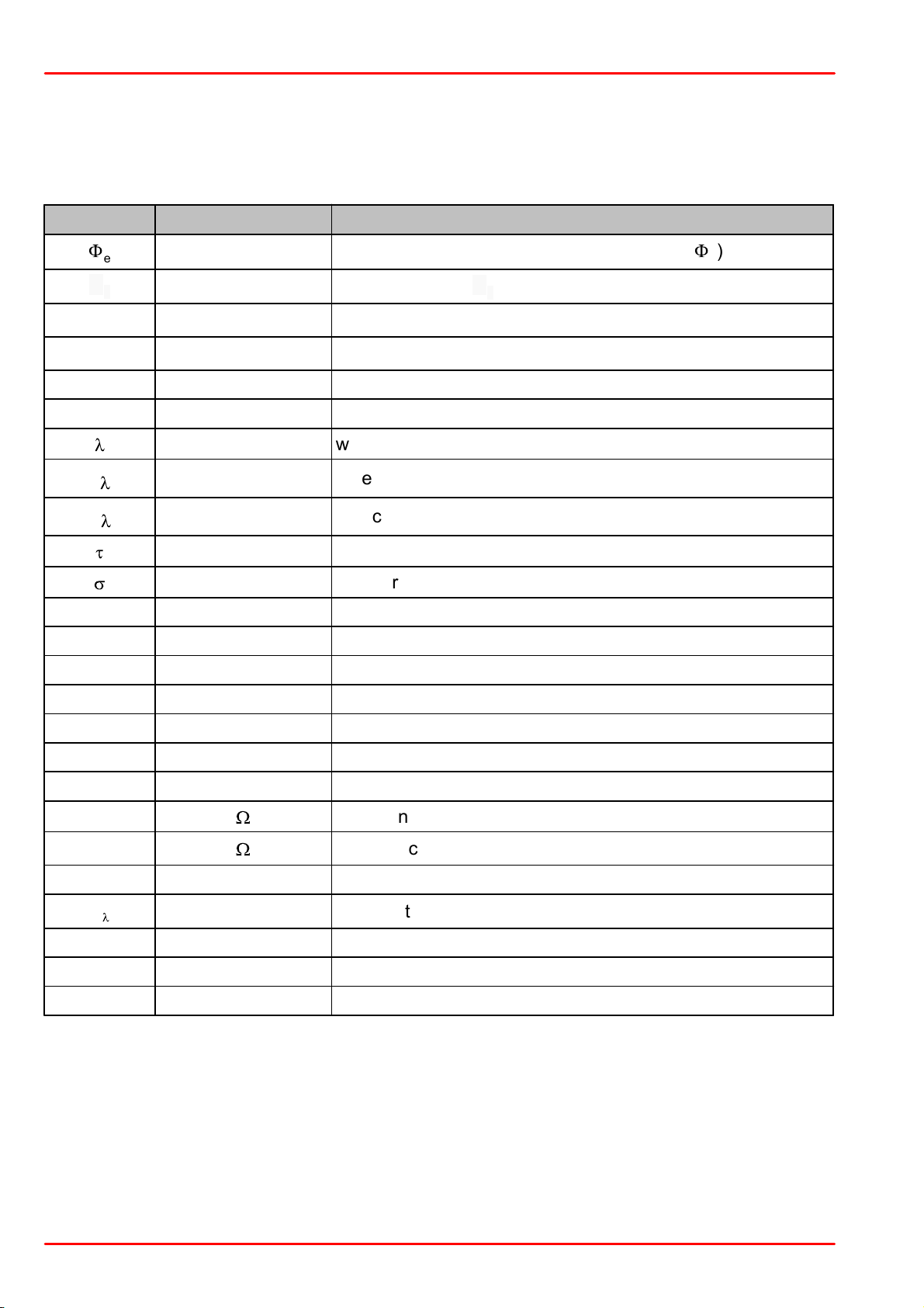
7.4 Symbols and Abbreviations
In the table below are listed symbols and abbreviations that are used in the PM400 User Interface.
© 2017 Thorlabs GmbH60
Page 63

7 Appendix
7.5 Warranty
Thorlabs GmbH warrants material and production of the PM400 for a period of 24 months starting with the date of shipment. During this warranty period Thorlabs GmbH will see to defaults
by repair or by exchange if these are entitled to warranty.
For warranty repairs or service the unit must be sent back to Thorlabs GmbH. The customer will
carry the shipping costs to Thorlabs GmbH, in case of warranty repairs Thorlabs GmbH will carry the shipping costs back to the customer.
If no warranty repair is applicable the customer also has to carry the costs for back shipment.
In case of shipment from outside EU duties, taxes etc. which should arise have to be carried by
the customer.
Thorlabs GmbH warrants the hard- and/or software determined by Thorlabs GmbH for this unit
to operate fault-free provided that they are handled according to our requirements. However,
Thorlabs GmbH does not warrant a fault free and uninterrupted operation of the unit, of the
software or firmware for special applications nor this instruction manual to be error free. Thorlabs GmbH is not liable for consequential damages.
Restriction of warranty
The warranty mentioned before does not cover errors and defects being the result of improper
treatment, software or interface not supplied by us, modification, misuse or operation outside
the defined ambient stated by us or unauthorized maintenance.
Further claims will not be consented to and will not be acknowledged. Thorlabs GmbH does explicitly not warrant the usability or the economical use for certain cases of application.
Thorlabs GmbH reserves the right to change this instruction manual or the technical data of the
described unit at any time.
© 2017 Thorlabs GmbH
61
Page 64

PM400
7.6 Copyright and Exclusion of Reliability
Thorlabs GmbH has taken every possible care in preparing this document. We however assume no liability for the content, completeness or quality of the information contained therein. The
content of this document is regularly updated and adapted to reflect the current status of the
hardware and/or software. We furthermore do not guarantee that this product will function without errors, even if the stated specifications are adhered to.
Under no circumstances can we guarantee that a particular objective can be achieved with the
purchase of this product.
Insofar as permitted under statutory regulations, we assume no liability for direct damage, indirect damage or damages suffered by third parties resulting from the purchase of this product. In
no event shall any liability exceed the purchase price of the product.
Please note that the content of this document is neither part of any previous or existing agreement, promise, representation or legal relationship, nor an alteration or amendment thereof. All
obligations of Thorlabs GmbH result from the respective contract of sale, which also includes
the complete and exclusively applicable warranty regulations. These contractual warranty regulations are neither extended nor limited by the information contained in this document. Should
you require further information on this product, or encounter specific problems that are not discussed in sufficient detail in the document, please contact your local Thorlabs GmbH dealer or
system installer.
All rights reserved. This document may not be reproduced, transmitted or translated to another
language, either as a whole or in parts, without the prior written permission of Thorlabs GmbH.
Copyright © Thorlabs GmbH 2017. All rights reserved.
© 2017 Thorlabs GmbH62
Page 65

7 Appendix
Crossed out
"Wheelie Bin" symbol
7.7 Thorlabs 'End of Life' Policy
As required by the WEEE (Waste Electrical and Electronic Equipment Directive) of the European Community and the corresponding national laws, Thorlabs GmbH offers all end users in
the EC the possibility to return “end of life” units without incurring disposal charges.
This offer is valid for Thorlabs GmbH electrical and electronic equipment
·
sold after August 13th 2005
·
marked correspondingly with the crossed out “wheelie bin” logo (see figure below)
·
sold to a company or institute within the EC
·
currently owned by a company or institute within the EC
·
still complete, not disassembled and not contaminated
As the WEEE directive applies to self contained operational electrical and electronic products,
this “end of life” take back service does not refer to other Thorlabs GmbH products, such as
·
pure OEM products, that means assemblies to be built into a unit by the user (e. g. OEM
laser driver cards)
·
components
·
mechanics and optics
·
left over parts of units disassembled by the user (PCB’s, housings etc.).
Waste treatment on your own responsibility
If you do not return an “end of life” unit to Thorlabs GmbH, you must hand it to a company specialized in waste recovery. Do not dispose of the unit in a litter bin or at a public waste disposal
site.
WEEE Number (Germany) : DE97581288
Ecological background
It is well known that waste treatment pollutes the environment by releasing toxic products during decomposition. The aim of the European RoHS Directive is to reduce the content of toxic
substances in electronic products in the future.
The intent of the WEEE Directive is to enforce the recycling of WEEE. A controlled recycling of
end-of-life products will thereby avoid negative impacts on the environment.
© 2017 Thorlabs GmbH
63
Page 66

PM400
USA, Canada, and South America
Thorlabs, Inc.
56 Sparta Avenue
Newton, NJ 07860
USA
Tel: 973-579-7227
Fax: 973-300-3600
www.thorlabs.com
www.thorlabs.us (West Coast)
Email: [email protected]
Support: [email protected]
UK and Ireland
Thorlabs Ltd.
1 Saint Thomas Place, Ely
Cambridgeshire CB7 4EX
United Kingdom
Tel: +44-1353-654440
Fax: +44-1353-654444
www.thorlabs.com
Email: [email protected]
Support: [email protected]
Europe
Thorlabs GmbH
Hans-Böckler-Str. 6
85221 Dachau
Germany
Tel: +49-8131-5956-0
Fax: +49-8131-5956-99
www.thorlabs.de
Email: [email protected]
Scandinavia
Thorlabs Sweden AB
Bergfotsgatan 7
431 35 Mölndal
Sweden
Tel: +46-31-733-30-00
Fax: +46-31-703-40-45
www.thorlabs.com
Email: [email protected]
France
Thorlabs SAS
109, rue des Côtes
78600 Maisons-Laffitte
France
Tel: +33-970 444 844
Fax: +33-811 38 17 48
www.thorlabs.com
Email: [email protected]
Brazil
Thorlabs Vendas de Fotônicos Ltda.
Rua Riachuelo, 171
São Carlos, SP 13560-110
Brazil
Tel: +55-16-3413 7062
Fax: +55-16-3413 7064
www.thorlabs.com
Email: [email protected]
Japan
Thorlabs Japan, Inc.
Higashi Ikebukuro
Q Building 2nd Floor 2-23-2
Toshima-ku, Tokyo 170-0013
Japan
Tel: +81-3-5979-8889
Fax: +81-3-5979-7285
www.thorlabs.jp
Email: [email protected]
China
Thorlabs China
Room A101, No. 100
Lane 2891, South Qilianshan Road
Putuo District
Shanghai 200331
China
Tel: +86-21-60561122
Fax: +86-21-32513480
www.thorlabs.com
Email: [email protected]
7.8 Thorlabs Worldwide Contacts
© 2017 Thorlabs GmbH64
Page 67

Page 68

www.thorlabs.com
 Loading...