

Page 1

TP 92
Bedienungsanleitung
User Manual
®
Mode d’Emploi
Page 2

www.thorens.com
Page 3

TP 92
Bedienungsanleitung
User Manual
Mode d’Emploi
Page 4
Inhalt
TONARM UND TONABNEHMERSYSTEM 6
AUFLAGEKRAFT 7
ANTISKATINGKRAFT 8
WEITERE TONARMEINSTELLUNGEN 9
TECHNISCHE DATEN 11
Page 5

Table of Contents Sommaire
TONEARM AND PICK-UP CARTRIDGE 13
TRACKING FORCE 14
ANTI-SKATING FORCE (BIAS) 15
FURTHER TONEARM ADJUSTMENTS 16
TECHNICAL SPECIFICATIONS 18
BRAS ET CELLULE DE LECTURE 20
FORCE D’APPUI 21
FORCE ANTISKATING 22
AUTRES REGLAGES DU BRAS DE LECTURE 23
CARACTERISTIQUES TECHNIQUES 25
Page 6
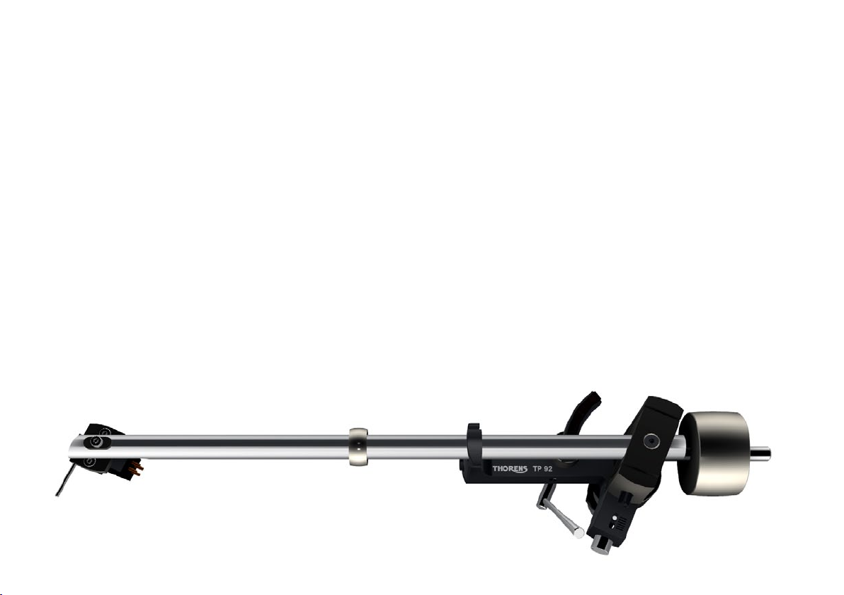
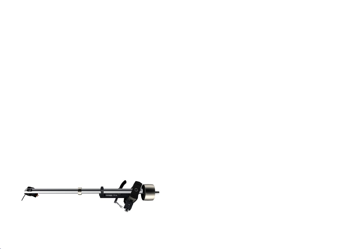
Tonarm und Tonabnehmersystem
Das Tonarmgewicht wurde zum Transport entfernt.
Drehen Sie dieses bei Montage des Plattenspielers von
hinten auf den Tonarm und stellen Sie anschließend die
Auagekraft ein. ➔ Seite 7
Am Tonarm TP 92 können nahezu alle auf dem Markt
befindlichen Tonabnehmer mit einem Abstand der Befestigungslöcher von 12,5 mm (½ ”) montiert werden.
6
Zum Anschluss des Tonabnehmersystems werden die
vier farblich gekennzeichneten Anschlußlitzen auf die
entsprechenden Anschluß-Stifte des Tonabnehmers
geschoben.
Verbinden Sie nach folgendem Schema, falls der Tonabnehmer keine Farbkennung aufweist:
R rechter Kanal (Signal) ➔ rot
G rechter Kanal (Masse) ➔ grün
L linker Kanal (Signal) ➔ weiß
G linker Kanal (Masse) ➔ blau
Abb. 1
Page 7
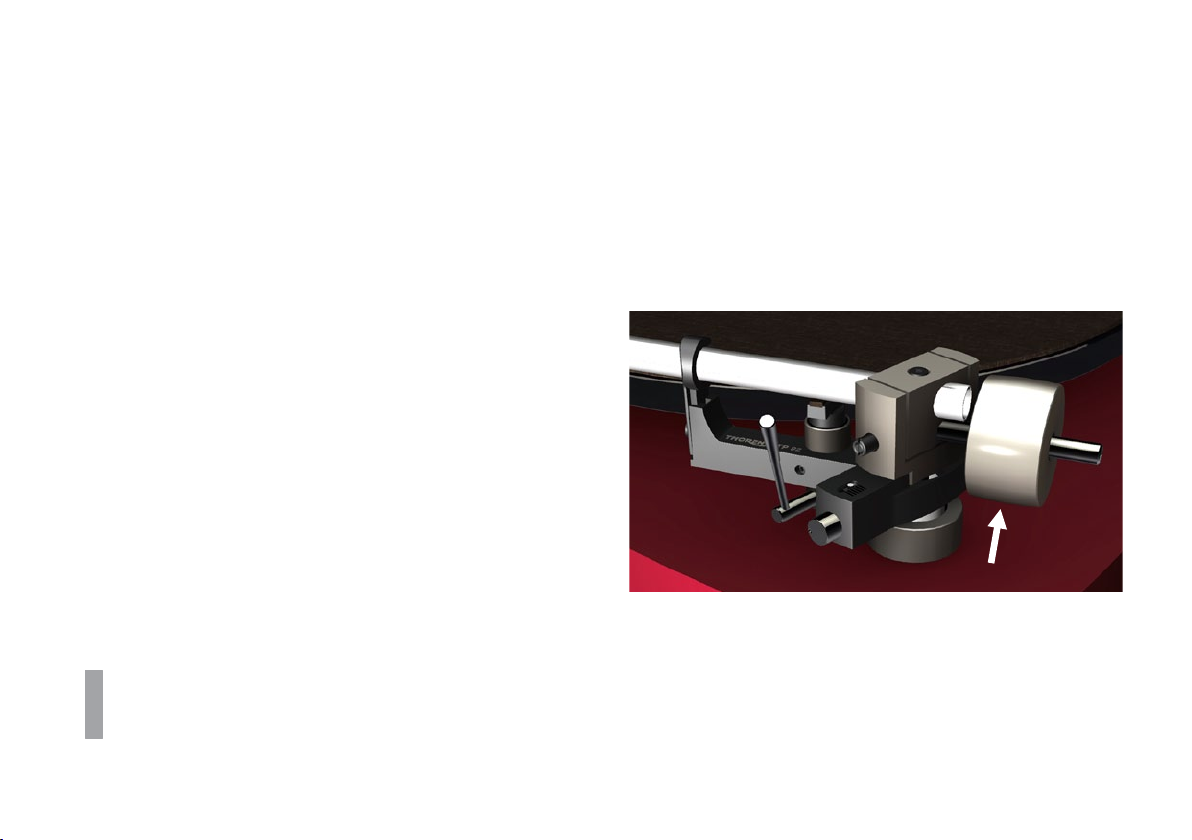
Auagekraft
Die Einstellung der Auagekraft erfolgt durch drehen
des Tonarmgewichts (➔ Abb. 2). Je weiter das Gewicht
nach vorne zum Tonabnehmer hin gedreht wird desto
größer wird die Auflagekraft.
Die korrekte Auflagekraft können Sie mit Hilfe der beiliegenden Tonarmwaage einstellen. Schwenken Sie hier-
zu den Tonarm bei abgesenktem Tonarmlift über den
Plattenteller und senken Sie ihn vorsichtig ab, so dass
die Nadel auf der Tonarmwaage aufliegt. Entfernen Sie
dabei unbedingt die Schutzhaube des Tonabnehmers.
Gehen Sie äußerst vorsichtig vor, um die Nadel des
Tonabnehmers nicht zu beschädigen!
Hinweis: Die korrekte Auagekraft ist vom verwendeten Tonabnehmer abhängig. Bitte konsultieren Sie
hierzu die Bedienungsanleitung Ihres Tonabnehmers.
Abb. 2
Das in der Mitte des Tonarmrohres angebrachte
Ringgewicht (➔ Abb. 1) darf nicht verschoben werden.
Es handelt sich um einen Resonanzdämpfer, der nur
exakt an dieser Position wirksam ist!
7
Page 8
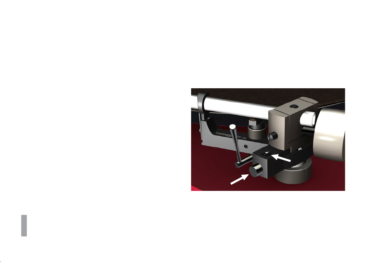
Antiskatingkraft
Durch Zusammenwirken der Reibungskraft der Plattenrillen mit den Lagerkräften am Tonabnehmer wird beim
Abspielen einer Schallplatte eine Kraftkomponente erzeugt, die den Tonarm nach innen zieht: Die Skatingkraft. Zu ihrer Kompensation dient die Antiskatingkraft,
welche beim Tonarm TP 92 durch einen eingebauten
Magneten erzeugt wird.
Die Antiskatingkraft ist bei Auslieferung voreingestellt,
sie kann jedoch bei Bedarf über eine Stellschraube
(➔ Abb. 3) angepasst werden.
Drehen Sie entgegen dem Uhrzeigersinn um die
Kraft zu erhöhen und im Uhrzeigersinn um die Kraft
zu verringern. Der weiße Punkt über der Stellschraube
dient dabei der Anzeige der aktuellen Einstellung.
Die benötigte Antiskatingkraft ist vom verwendeten
Tonabnehmer abhängig und sollte bei einem Wechsel mithilfe einer Meßschallplatte ermittelt werden.
8
Abb. 3
Page 9
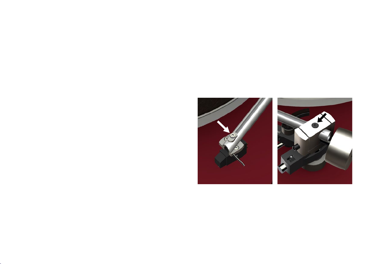
Weitere Tonarmeinstellungen
Der Überhang kann beim Wechseln des Tonabnehmers
am Headshell um ± 2,5 mm angepasst werden. Lösen
Sie hierzu die Schraube oberhalb des Headshells und
verschieben Sie dieses entsprechend. ➔ Abb. 4
Am hinteren Ende des Tonarmrohrs kann der Überhang
um weitere ± 3 mm und der Azimuth um ± 5° angepasst
werden. Lösen Sie hierzu die Schraube oben am Lagerblock mit einem Inbusschlüssel SW 2 ➔ Abb. 5
Änderung des VTA ➔ Seite 10
Die Schrauben dürfen nach der Anpassung nicht zu
sehr festgezogen werden!
Abb. 4
Abb. 5
9
Page 10

Weitere Tonarmeinstellungen
Änderungen des VTA können durch Anheben und Absenken des gesamten Tonarms vorgenommen wer-
den. Lösen Sie hierzu die Kontermutter (➔ Abb. 3) auf
der Unterseite und drehen Sie die Einstellmutter auf
der Oberseite, bis die gewünschte Tonarmhöhe erreicht
ist.
Nach einer Änderung des VTA muss auch der Tonarm-
lift nachjustiert werden. Hierzu benötigen Sie einen Inbusschlüssel SW 1,5. Lösen Sie die Arretierschraube
des Lifts und verschieben Sie den gesamten Lift vorsichtig nach oben oder unten. ➔ Abb. 7
Im Allgemeinen sollte das Tonarmrohr parallel zur
Plattentelleroberäche stehen. Kleine Veränderungen an VTA oder Tonarmlift haben große Auswirkungen. Überprüfen Sie nach jeder Änderung die Höhe
des Tonabnehmers über der Schallplatte und ob die
Liftbank den Tonarm beim Abspielen vollständig frei
gibt (Abstand min. 1 mm).
10
Abb. 6
Abb. 9
Page 11

Technische Daten
Tonarm Spezikation
Montageabstand
Effektive Länge
Überhang
Kröpfungswinkel
Innerer Nulldurchgang
Äusserer Nulldurchgang
Effektive Masse
Maximale Verzerrung zwischen
den Nullduchgängen
Geometrie
Gewicht
Anschluss
Montagebohrung
Antiskating
Technische Änderungen vorbehalten. Made in Germany.
9“
215 mm
232,8 mm
17,8 mm
23,66°
66,0 mm
120,9 mm
11 g
0,63%
Baerwald / Löfgren „A“
0,360 kg
lose Kabel oder Mini DIN (nur OEM Version)
18 mm Durchmesser
Ferritmagnete, reibungsfrei
11
Page 12

Notizen
12
Page 13

Tonearm and Pick-Up Cartridge
The tonearm counterweight has been removed for
shipping. Screw the counterweight onto the rear end of
the tonearm and adjust the tracking force. ➔ Page 13
The TP 92 tonearm can accommodate most pick-up
cartridges with a distance of 12.5 mm (½ ”) between the
mounting holes.
To connect the pick-up cartridge, push the four colourcoded cartridge tags onto the cartridge pins.
If the cartridge pins are not colour-coded, connect them
as follows:
R right channel (signal) ➔ red
G right channel (earth) ➔ green
L left channel (signal) ➔ white
G left channel (earth) ➔ blue
Fig. 1
13
Page 14

Tracking Force
The tracking force can be adjusted by rotating the tonearm counterweight (➔ Fig. 2). The closer the counter-
weight is to the cartridge, the higher the tracking force.
The tracking force can be set with the help of the supplied stylus balance. Lower the tonearm lift, move the
tonearm out over the platter and carefully lower it until
the stylus of the pick-up cartridge comes to rest on the
stylus balance. The stylus guard must be removed for
this procedure.
Great care should be taken to avoid damaging the
stylus.
Note: Refer to the user manual of your pick-up cartridge to determine the correct tracking force.
14
Fig. 2
Do not move the ring that sits around the middle of
the tonearm tube (➔ Fig. 1). It serves as a vibration
damper and is effective only at its original position.
Page 15

Anti-Skating Force (Bias)
The interaction of stylus friction and cartridge-bearing
forces produces a force which pulls the tonearm towards the centre of the record (referred to as skating
force). This force can be offset with the help of anti-skating force, which, in the case of the TP 92, is produced
by a magnet incorporated into the tonearm.
The anti-skating force is factory-adjusted. If neces-
sary, it can be readjusted with the help of an adjust-
ment screw. ➔ Fig. 3
Turn the adjustment screw anti-clockwise to increase,
and clockwise to decrease the anti-skating force. The
white dot above the adjustment screw indicates the setting.
The amount of anti-skating force required depends
on the type of pick-up cartridge used. If you change
the cartridge for a different type, use a test record
to determine how much anti-skating force is required.
Fig. 3
15
Page 16

Further Tonearm Adjustments
The tonearm headshell allows an overhang adjustment
of ± 2,5 mm to be made. To adjust overhang, loosen the
screw holding the headshell and move the headshell as
required. ➔ Fig. 4
A screw at the rear of the tonearm allows a further over-
hang adjustment of ±3 mm as well as an azimuth adjustment of ±5°. The screw is recessed into the top of
the bearing housing and can be loosened with a 2-mm
hex key. ➔ Fig. 5
The vertical tracking angle (VTA) can be adjusted by
raising or lowering the tonearm. ➔ Page 16
Take care not to over-tighten the screws after making
adjustments.
Fig. 4
Fig. 5
16
Page 17

Further Tonearm Adjustments
The vertical tracking angle (VTA) can be adjusted by
raising or lowering the entire tonearm. Loosen the lock
nut (➔ Fig. 6) on the underside of the turntable; then turn
the adjustment ring above the base to raise or lower the
tonearm as required.
If the VTA is changed, the tonearm lift will need to be
to be readjusted. Loosen the locking screw on the tonearm lift with a 1.5-mm hex key and carefully raise or
lower the entire lift. ➔ Fig. 7
The tonearm tube should be parallel to the platter
surface. Small adjustments of the VTA or the tonearm
lift height can have a large effect. After making any
changes, you should therefore always check whether
there is enough clearance (at least 1 mm) between
the cartridge and the record (when the lift is engaged)
and between the tonearm lift pad and the tonearm
tube (when the lift is disengaged).
Fig. 6
Fig. 7
17
Page 18

Technical Specications
Tonearm specication
Distance tonearm pivot
to stylus
Effective length
Stylus overhang
Angular offset
Inner null
Outer null
Effective mass
Maximum distortion
between null-points
Geometry
Weight
Connectors
Mounting hole
Antiskating
Technical specifications subject to change without notice. Made in Germany.
18
9”
215 mm
232,8 mm
17,8 mm
23,66°
66,0 mm
120,9 mm
11 g
0,63%
Baerwald / Löfgren „A“
0,360 kg
wires for soldering or Mini-DIN connectors (OEM versions only)
18 mm dia
ferrite magnets, friction free
Page 19

Notes
19
Page 20

Bras et cellule de lecture
Le contrepoid du bras est retiré pour le transport. Vissez le à l’arrière du bras et réglez ensuite la force d’ap-
pui. ➔ Page 19
Vous pouvez monter sur le bras de lecture TP 92 pratiquement toutes les cellules de lecture du marché ayant
un écartement des trous de fixation de 12.5 mm (½ ”).
20
Pour le raccordement de la cellule de lecture, placez
les quatre cosses repérées par couleur sur les picots
de la cellule de lecture.
Procédez au raccordement selon le schéma suivant si
la cellule n’a pas de repère couleur :
R Canal droit (signal) ➔ rouge
G Canal droit (masse) ➔ vert
L Canal gauche (signal) ➔ blanc
G Canal gauche (masse) ➔ bleu
Fig. 1
Page 21

Force d’appui
La force d’appui se règle par la rotation du contrepoids
du bras de lecture (➔ Fig. 2). Plus le contrepoids est dé-
placé vers l’avant côté cellule de lecture, plus la force
d’appui augmente.
Vous pouvez régler la force d’appui correcte à l’aide
de la balance du bras de lecture livré. Abaissez le
lève-bras et déplacez le bras au dessus du plateau et
abaissez-le prudemment afin que l’aiguille repose sur
la balance. N’omettez surtout pas de retirer le capot de
protection de la cellule de lecture.
Procédez avec une extrême précaution, pour ne pas
endommager l’aiguille de la cellule de lecture !
Attention: La force d’appui correcte dépend de la cellule de lecture utilisée. Consultez le mode d’emploi
de votre cellule de lecture.
Fig. 2
La bague montée au milieu du tube du bras de lecture (➔ Fig. 1) ne doit pas être déplacée. Il s’agit d’un
amortisseur de résonance, qui n’est efficace que
dans cette position !
21
Page 22

Force antiskating
Un effet combiné de la force de frottement des sillons
du disque et des forces du palier du bras génère lors
de la lecture du disque une composante de forces, qui
tire le bras de lecture vers le centre : la force skating. La
force antiskating qui sert à la compenser est produite
par un aimant intégré au bras de lecture TP 92.
La force antiskating est préréglée avant livraison,
cependant en cas de besoin elle peut être adaptée à
l’aide d’une vis de réglage. ➔ Fig. 3
Une rotation antihoraire augmente la force antiskating, une rotation horaire la réduit. Le point blanc
placé au dessus de la vis de réglage sert de repère au
réglage actuel.
Fig. 3
La force antiskating nécessaire dépend du type de
cellule de lecture et devrait être dénie à l’aide d’un
disque de mesure en cas de remplacement.
22
Page 23

Autres réglages du bras de lecture
Lors du remplacement de la cellule le porte à faux peut
être réglé au porte cellule de ±2,5 mm. Desserrez pour
cela la vis placée au-dessus du porte cellule et déplacez celui-ci en conséquence. ➔ Fig. 4
Vous pouvez adapter le porte à faux de ±3 mm supplémentaire et l’azimut de ±5° à l’extrémité arrière du
bras de lecture. Desserrez pour ce faire la vis située
sur le dessus du bloc-palier à l’aide d’une clé six de
2 mm. ➔ Fig. 4
Pour obtenir un changement du VTA (vertical tracking
alignment), la hauteur du bras de lecture doit être modifiée. ➔ Page 22
Une fois le réglage terminé, ne pas serrer trop fortement les vis !
Fig. 4
Fig. 5
23
Page 24

Autres réglages du bras de lecture
Les modifications du VTA peuvent être obtenues par
une montée ou une descente de l’ensemble du bras
de lecture. Pour ce faire, desserrez le contre-écrou
(➔ Fig. 6) sous la face inférieure et tournez l’écrou de
réglage de la face supérieure jusqu’à obtention de la
hauteur souhaitée du bras de lecture.
Après un changement du VTA le lève-bras doit également être réajusté. Pour ce faire utiliser une clé six pans
de 1,5 mm. Desserrez la vis de blocage du lève-bras et
déplacez avec précaution l’ensemble du lève-bras vers
le haut ou vers le bas. ➔ Fig. 7
En principe, le tube du bras de lecture doit être parallèle à la surface du plateau. Des petites modications
du VTA ou du lève-bras ont des effets importants.
Vériez après chaque modication la hauteur de la
cellule de lecture au-dessus du disque et si le lèvebras libère totalement le bras de lecture pendant la
lecture (distance minimale 1 mm).
24
Fig. 6
Fig. 7
Page 25

Caractéristiques techniques
Tonearm specication
Distance tonearm pivot
to stylus
Effective length
Stylus overhang
Angular offset
Inner null
Outer null
Effective mass
Maximum distortion
between null-points
Geometry
Weight
Connectors
Mounting hole
Antiskating
Sous réserve de modifications techniques. Fabriqué en Allemagne.
9”
215 mm
232,8 mm
17,8 mm
23,66°
66,0 mm
120,9 mm
11 g
0,63%
Baerwald / Löfgren „A“
0,360 kg
wires for soldering or Mini-DIN connectors (OEM versions only)
18 mm dia
ferrite magnets, friction free
25
Page 26

Notes
26
Page 27

®
Thorens Export Company AG
Im Huebel 1, CH-4304 Giebenach
Copyright © 2012
www.thorens.com
Page 28

Printed in Germany · UM92OEM-0312-B
®
 Loading...