


THOR-SSM
Rev. : 02/09/2012 1
Welcome to the THOR Family!
Thank you for purchasing a THOR Small Switch! We appreciate your business, and we think
you’ll appreciate the many ways that your THOR system will save you money, time, and
effort.
The THOR Small Switch offers three fundamental uses:
• As a Multiplex Repeater: the DVI signals (+optional audio) coming from a signal
source are equalized and distributed on up to 7 equivalent outputs. A control is not
necessary. Distributed display systems can be realized (Digital Signage).
• As an 8-port Crosspoint Switch: each port can be switched optionally as an input or
output. You can, for example, switch and distribute the signals from 3 signal
sources on up to 5 displays (allowing simultaneous presentations on several
displays). Alternatively, signals coming from 7 signal sources can be switched in
turn to a single display. The changeover can be triggered remotely using the serial
interface (RS232) and/or by a push-button at the device.
• As a 7-port KVM Switch: up to 7 Single-head ports (a “Single-head” extender
system supports 1x monitor, 1x keyboard, 1x mouse) or up to 3 Dual-head ports (a
Dual-head extender system supports 2x monitor, 1x keyboard, 1x mouse). The
changeover can be triggered remotely using the serial interface (RS232) and/or by a
push-button at the device.
Cascade multiple devices in two stages for all applications to give up to 49/1 connections.
The THOR Small Switch has the advantage that it can be positioned up to 140m away from
both your signal source and display device. This becomes possible by using the proven
THOR Extender technology for the transmission of DVI- Monitor and USB-Keyboard and
Mouse signals over CATx- cable.
The operation of a THOR Small Switch always requires at least one Local Unit and up to
seven Remote Units from the THOR Extenders range.
DISCONTINUED

THOR-SSM
2
Rev. : 02/09/2012
Wherever long distances cause problems for remotely locating and switching a monitor
(keyboard/mouse) signal, e.g. airports, industrial plants, call centers or in distributed
computer centers, the THOR Small Switch is the best solution. Its flexibility allows it to
tackle many tasks.
In addition, there are 4 Media Extenders (DVI + optional audio) and 8 KVM- Extenders
(DVI+USB keyboard mouse + optional audio) available. The transmission of the signals
requires connecting CATx cable.
This manual will tell you all about your new THOR Small Switch, including how to install,
operate and troubleshoot it. For an introduction to the Converter, see Chapter 2.
The Converter product codes covered in this manual are:
8port THOR Small Switch devices:
TH-SSM-CAT THOR-SSM,SWITCH,SMALL,ON,CATx
TH-SSM-MM THOR-SSM,SWITCH,SMALL,ON,MULTIMODE
TH-SSM-SM THOR-SSM,SWITCH,SMALL,ON,SINGLEMODE
TH-SSM THOR-SSM,SWITCH,SMALL,FIBER,NO,GBIC
TH-SU THOR-SU,SWITCHING,UNIT
THOR KVM/DVI extending devices:
TH-E-KIT-1-SL-4-CAT
THOR,E,EXTENDER,KIT,1Mon,SL,4xHID,CATx
TH-E-KIT-1-SL-4-CAT-A232
THOR,E,EXTENDER,KIT,1Mon,SL,4xHID,CATx,Anal.Audio,RS232
TH-E-KIT-1-SL-4-CAT-DA
THOR,E,EXTENDER,KIT,1Mon,SL,4xHID,CATx,Dig.Audio
TH-E-KIT-1-SL-4-MM
THOR,E,EXTENDER,KIT,1Mon,SL,4xHID,MM,Fiber
TH-E-KIT-1-SL-4-MM-A232
THOR,E,EXTENDER,KIT,1Mon,SL,4xHID,MM,Fiber,Anal.Audio,RS232
TH-E-KIT-1-SL-4-MM-DA
THOR,E,EXTENDER,KIT,1Mon,SL,4xHID,MM,Fiber,Dig.Audio
TH-E-KIT-1-SL-4-SM
THOR,E,EXTENDER,KIT,1Mon,SL,4xHID,SM,Fiber
TH-E-KIT-1-SL-4-SM-A232
THOR,E,EXTENDER,KIT,1Mon,SL,4xHID,SM,Fiber,Anal.Audio,RS232
TH-E-KIT-1-SL-4-SM-DA
THOR,E,EXTENDER,KIT,1Mon,SL,4xHID,SM,Fiber,Dig.Audio
TH-E-KIT-1-SL-2-CAT
THOR,E,EXTENDER,KIT,1Mon,SL,2xHID,CATx
TH-E-KIT-1-SL-2-CAT-A232
THOR,E,EXTENDER,KIT,1Mon,SL,2xHID,CATx,Anal.Audio,RS232
TH-E-KIT-1-SL-2-CAT-DA
THOR,E,EXTENDER,KIT,1Mon,SL,2xHID,CATx,Dig.Audio
TH-E-KIT-1-SL-2-CAT-V
THOR,E,EXTENDER,KIT,1Mon,SL,2xHID,CATx,VGA/IN
TH-E-KIT-1-SL-2-MM
THOR,E,EXTENDER,KIT,1Mon,SL,2xHID,MM,Fiber

THOR-SSM
Rev. : 02/09/2012
3
TH-E-KIT-1-SL-2-MM-A232
THOR,E,EXTENDER,KIT,1Mon,SL,2xHID,MM,Fiber,Anal.Audio,RS232
TH-E-KIT-1-SL-2-MM-DA
THOR,E,EXTENDER,KIT,1Mon,SL,2xHID,MM,Fiber,Dig.Audio
TH-E-KIT-1-SL-2-MM-V
THOR,E,EXTENDER,KIT,1Mon,SL,2xHID,MM,Fiber,VGA/IN
TH-E-KIT-1-SL-2-SM
THOR,E,EXTENDER,KIT,1Mon,SL,2xHID,SM,Fiber
TH-E-KIT-1-SL-2-SM-A232
THOR,E,EXTENDER,KIT,1Mon,SL,2xHID,SM,Fiber,Anal.Audio,RS232
TH-E-KIT-1-SL-2-SM-DA
THOR,E,EXTENDER,KIT,1Mon,SL,2xHID,SM,Fiber,Dig.Audio
TH-E-KIT-1-SL-2-SM-V
THOR,E,EXTENDER,KIT,1Mon,SL,2xHID,SM,Fiber,VGA/IN
TH-E-KIT-1-SL-24-CAT
THOR,E,EXTENDER,KIT,1Mon,SL,2xHID,4xUSB2,CATx
TH-E-KIT-1-SL-24-CATA232
THOR,E,EXTENDER,KIT,1Mon,SL,2xHID,4xUSB2,CATx,Anal.RS232
TH-E-KIT-1-SL-24-CAT-DA
THOR,E,EXTENDER,KIT,1Mon,SL,2xHID,4xUSB2,CATx,Dig.Audio
TH-E-KIT-1-SL-24-MM
THOR,E,EXTENDER,KIT,1Mon,SL,2xHID,4xUSB2,MM,Fiber
TH-E-KIT-1-SL-24-MM-A232
THOR,E,EXTENDER,KIT,1Mon,SL,2xHID,4xUSB2,MM,Fiber,Anal.Audio,RS232
TH-E-KIT-1-SL-24-MM-DA
THOR,E,EXTENDER,KIT,1Mon,SL,2xHID,4xUSB2,MM,Fiber,Dig.Audio
TH-E-KIT-1-SL-24-SM
THOR,E,EXTENDER,KIT,1Mon,SL,2xHID,4xUSB2,SM,Fiber
TH-E-KIT-1-SL-24-SM-A232
THOR,E,EXTENDER,KIT,1Mon,SL,2xHID,4xUSB2,SM,Fiber,Anal.Audio,RS232
TH-E-KIT-1-SL-24-SM-DA
THOR,E,EXTENDER,KIT,1Mon,SL,2xHID,4xUSB2,SM,Fiber,Dig.Audio
TH-E-KIT-2-SL-4-CAT
THOR,E,EXTENDER,KIT,2Mon,SL,4xHID,CATx
TH-E-KIT-2-SL-4-CAT-A232
THOR,E,EXTENDER,KIT,2Mon,SL,4xHID,CATx,Anal.Audio,RS232
TH-E-KIT-2-SL-4-CAT-DA
THOR,E,EXTENDER,KIT,2Mon,SL,4xHID,CATx,Dig.Audio
TH-E-KIT-2-SL-4-MM
THOR,E,EXTENDER,KIT,2Mon,SL,4xHID,MM,Fiber
TH-E-KIT-2-SL-4-MM-A232
THOR,E,EXTENDER,KIT,2Mon,SL,4xHID,MM,Fiber,Anal.Audio,RS232
TH-E-KIT-2-SL-4-MM-DA
THOR,E,EXTENDER,KIT,2Mon,SL,4xHID,MM,Fiber,Dig.Audio
TH-E-KIT-2-SL-4-SM
THOR,E,EXTENDER,KIT,2Mon,SL,4xHID,SM,Fiber
TH-E-KIT-2-SL-4-SM-A232
THOR,E,EXTENDER,KIT,2Mon,SL,4xHID,SM,Fiber,Anal.Audio,RS232
TH-E-KIT-2-SL-4-SM-DA
THOR,E,EXTENDER,KIT,2Mon,SL,4xHID,SM,Fiber,Dig.Audio
TH-E-KIT-2-SL-24-CAT
THOR,E,EXTENDER,KIT,2Mon,SL,2xHID,4xUSB2,CATx
TH-E-KIT-2-SL-24-CATA232
THOR,E,EXTENDER,KIT,2Mon,SL,2xHID,4xUSB2,CATx,Anal.Audio,RS232
TH-E-KIT-2-SL-24-CAT-DA
THOR,E,EXTENDER,KIT,2Mon,SL,2xHID,4xUSB2,CATx,Dig.Audio
TH-E-KIT-2-SL-24-MM
THOR,E,EXTENDER,KIT,2Mon,SL,2xHID,4xUSB2,MM,Fiber
TH-E-KIT-2-SL-24-MM-A232
THOR,E,EXTENDER,KIT,2Mon,SL,2xHID,4xUSB2,MM,Fiber,Anal.Audio,RS232
TH-E-KIT-2-SL-24-MM-DA
THOR,E,EXTENDER,KIT,2Mon,SL,2xHID,4xUSB2,MM,Fiber,Dig.Audio
TH-E-KIT-2-SL-24-SM
THOR,E,EXTENDER,KIT,2Mon,SL,2xHID,4xUSB2,SM,Fiber
TH-E-KIT-2-SL-24-SM-A232
THOR,E,EXTENDER,KIT,2Mon,SL,2xHID,4xUSB2,SM,Fiber,Anal.Audio,RS232
TH-E-KIT-2-SL-24-SM-DA
THOR,E,EXTENDER,KIT,2Mon,SL,2xHID,4xUSB2,SM,Fiber,Dig.Audio
TH-E-KIT-4-SL-8-CAT
THOR,E,EXTENDER,KIT,4Mon,SL,8xHID,CATx
TH-E-KIT-4-SL-8-CAT-A232
THOR,E,EXTENDER,KIT,4Mon,SL,8xHID,CATx,Anal.Audio,RS232
TH-E-KIT-4-SL-8-CAT-DA
THOR,E,EXTENDER,KIT,4Mon,SL,8xHID,CATx,Dig.Audio
TH-E-KIT-4-SL-8-MM
THOR,E,EXTENDER,KIT,4Mon,SL,8xHID,MM,Fiber

THOR-SSM
4
Rev. : 02/09/2012
TH-E-KIT-4-SL-8-MM-A232
THOR,E,EXTENDER,KIT,4Mon,SL,8xHID,MM,Fiber,Anal.Audio,RS232
TH-E-KIT-4-SL-8-MM-DA
THOR,E,EXTENDER,KIT,4Mon,SL,8xHID,MM,Fiber,Dig.Audio
TH-E-KIT-4-SL-8-SM
THOR,E,EXTENDER,KIT,4Mon,SL,8xHID,SM,Fiber
TH-E-KIT-4-SL-8-SM-A232
THOR,E,EXTENDER,KIT,4Mon,SL,8xHID,SM,Fiber,Anal.Audio,RS232
TH-E-KIT-4-SL-8-SM-DA
THOR,E,EXTENDER,KIT,4Mon,SL,8xHID,SM,Fiber,Dig.Audio
TH-E-KIT-4-SL-24-CAT
THOR,E,EXTENDER,KIT,4Mon,SL,2xHID,4xUSB2,CATx
TH-E-KIT-4-SL-24-CATA232
THOR,E,EXTENDER,KIT,4Mon,SL,2xHID,4xUSB2,CATx,Anal.Audio,RS232
TH-E-KIT-4-SL-24-CAT-DA
THOR,E,EXTENDER,KIT,4Mon,SL,2xHID,4xUSB2,CATx,Dig.Audio
TH-E-KIT-4-SL-24-MM
THOR,E,EXTENDER,KIT,4Mon,SL,2xHID,4xUSB2,MM,Fiber
TH-E-KIT-4-SL-24-MM-A232
THOR,E,EXTENDER,KIT,4Mon,SL,2xHID,4xUSB2,MM,Fiber,Anal.Audio,RS232
TH-E-KIT-4-SL-24-MM-DA
THOR,E,EXTENDER,KIT,4Mon,SL,2xHID,4xUSB2,MM,Fiber,Dig.Audio
TH-E-KIT-4-SL-24-SM
THOR,E,EXTENDER,KIT,4Mon,SL,2xHID,4xUSB2,SM,Fiber
TH-E-KIT-4-SL-24-SM-A232
THOR,E,EXTENDER,KIT,4Mon,SL,2xHID,4xUSB2,SM,Fiber,Anal.Audio,RS232
TH-E-KIT-4-SL-24-SM-DA
THOR,E,EXTENDER,KIT,4Mon,SL,2xHID,4xUSB2,SM,Fiber,Dig.Audio

THOR-SSM
Rev. : 02/09/2012
5
Copyrights and Trademarks
©2009. All rights reserved. This information may not be reproduced in any manner without
the prior written consent of the manufacturer.
Information in this document is subject to change without notice and the manufacturer shall
not be liable for any direct, indirect, special, incidental or consequential damages in
connection with the use of this material.
All trademark and trade names mentioned in this document are acknowledged to be the
property of their respective owners.
Disclaimer
While every precaution has been taken in the preparation of this manual, the manufacturer
assumes no responsibility for errors or omissions. Neither does the manufacturer assume any
liability for damages resulting from the use of the information contained herein. The
manufacturer reserves the right to change the specifications, functions, or circuitry of the
product without notice.
The manufacturer cannot accept liability for damage due to misuse of the product or due to
any other circumstances outside the manufacturer’s control (whether environmental or
installation related). The manufacturer shall not be responsible for any loss, damage, or injury
arising directly, indirectly, or consequently from the use of this product.
Cautions and Notes
The following symbols are used in this guide:
CAUTION: This indicates an important operating instruction
that should be followed to avoid any potential damage to
hardware or property, loss of data, or personal injury.
NOTE. This indicates important information to help you make the best use of
this product.

THOR-SSM
6
Rev. : 02/09/2012
EC DECLARATION OF CONFORMITY
The products listed in this manual in the form as delivered are in conformity with the
provisions of the following European Directives:
2004/108/EG Council Directive on the approximation of the laws of the Member States
relating to electromagnetic compatibility
CE-marking 2009
List on page 2 and 3
Conformity to the Directives is assured through the application of the following
standards:
EN 55022: 09/2006 Class A
IEC 61000-4-2: 02/2001
IEC 61000-4-3: 05/2006
IEC 61000-4-4: 12/2004
IEC 61000-4-5: 11/2006
This declaration certifies the conformity to the specified directives but contains no
assurance of properties. The safety documentation noted in this manual shall be
considered in detail. The length of the attached CPU- or Console Cables must not exceed
3m. The use of suggested interconnect cables is mandatory.
WARNING: This equipment has been found to comply with the limits for a Class A digital
device, pursuant to Part 15 of the FCC Rules. These limits are designed to provide reasonable
protection against harmful interference when the equipment is operated in a commercial
environment. This equipment generates, uses, and can radiate radio frequency energy and, if
not installed and used in accordance with the instruction manual, may cause harmful
interference to radio communications. Operation of this equipment in a residential area is
likely to cause harmful interference in which case the user will be required to correct the
interference at his own expense.

SAFETY-PRECAUTIONS AND
INSTALLATION GUIDLINES
Rev. : 02/09/2012
7
Safety Precautions and Installation Guidelines
To ensure reliable and safe long-term operation, please note the following installation
guidelines:
• Do not use CATx- devices to link between buildings – please use fiber devices.
• Only use in dry, indoor environments.
• If the building has 3-phase AC power, try to ensure that equipment connected to the
Local and Remote Units is on the same phase.
• Try not to route a CATx- link cable alongside power cables.
• The THOR Small Switch Unit, Remote Unit, Local Unit and any power supplies can get
warm. Do not locate them in an enclosed space without any airflow.
• Do not place a power supply directly on top of a unit.
• Do not obscure a unit’s ventilation holes.
To safeguard against personal injury and avoid possible
damage to equipment or property, please observe the
following:
• Only use power supplies originally supplied with the
product or manufacturer-approved replacements. Do not
attempt to dismantle or repair any power supply. Do not
use a power supply if it appears to be defective or has a
damaged case.
• Connect all power supplies to grounded outlets. In each
case, ensure that the ground connection is maintained
from the outlet socket through to the power supply’s AC
power input.
• Do not attempt to modify or repair this product, or make
a connection from the CATx- link interface (RJ45) to any
other products, especially telecommunications or
network equipment.

THOR-SSM
8
Rev. : 02/09/2012

CONTENTS
Rev. : 02/09/2012
9
Contents
1. Quick Setup 14
2. Overview 15
2.1 Introduction 15
2.2 Glossary 16
2.3 Example of a THOR Small Switch System 17
2.4 Features 18
2.5 Product Range 19
2.6 Compatibility 23
Interface Compatibility 23
2.7 How to Use This Guide 24
Connection & Compatibility 24
DDC Information 24
Selecting the moment of switching to the next frame 24
Selection of Color reduction for transfer acceleration 24
3. Installation 25
3.1 Package Contents 25
3.2 Interconnection Cable Requirements 28
3.3 System Setup 30
3.4 Installation Instructions 33
4. Device Views 34
4.1 THOR Small Switch for CATx 34
Configuration ‘Multiplex-Repeater’ – 1 Source up to 7 Displays 34
Configuration ‘Multiplex-Repeater’ – 2 Sources / each up to 3 Displays 34
Configuration ‘Multiplex-Repeater’ – 4 Sources on 4 Displays 35
Configuration ‘Crosspoint-Switch’ 1 Input / 7 Outputs 35
Configuration ‘Crosspoint-Switch’ 2 Inputs / 6 Outputs 36
Configuration ‘Crosspoint-Switch’ 3 Inputs / 5 Outputs 36
Configuration ‘Crosspoint-Switch’ 4 Inputs / 4 Outputs 37
Configuration ‘Crosspoint-Switch’ 5 Inputs / 3 Outputs 37
Configuration ‘Crosspoint-Switch’ 6 Inputs / 2 Outputs 38
Configuration ‘Crosspoint-Switch’ 7 Inputs / 1 Output 38
Configuration ‘Single-head KVM-Switch’ 39
Configuration ‘Dual-head KVM-Switch’ 39
4.2 THOR Media Extender 41
4.3 THOR KVM Extender 43
5. Diagnostic 54
5.1 THOR Small Switch for CATx 54

THOR-SSM
10
Rev. : 02/09/2012
5.2 THOR Small Switch for CATx 55
5.3 THOR Media/ KVM Extender 56
6. Service Setup 57
6.1 THOR Small Switch for CATx 57
Operating Mode Selection 58
Connection of THOR Control External Switching Device (Accessories) 60
6.2 THOR Media/ KVM Extender 62
6.3 Setup at the Local Unit 63
DDC / color depth 63
Loading the DDC Information from the Remote Monitor into the internal DDC Table 64
Selection of Color depth 64
6.4 Setup at the Remote Unit 65
Selecting the moment of switching to the next frame 65
7. Operating Modes 66
7.1 Multiplex- Repeater 66
Configuration ‘Multiplex-Repeater’ – 1 Source up to 7 Displays 66
Configuration ‘Multiplex-Repeater’ – 2 Sources, each up to 3 displays 67
Configuration ‘Multiplex-Repeater’ – 4 Sources on 4 Displays 67
Example Applications: 68
Indicator LEDs 70
Meaning of the diagnostic LEDs: 70
Setup 71
Operation 71
By serial interface 71
Control commands 71
7.2 Crosspoint- Switch 72
Configuration ‘Crosspoint-Switch’ 1 Input / 7 Outputs 73
Configuration ‘Crosspoint-Switch’ 2 Inputs / 6 Outputs 73
Configuration ‘Crosspoint-Switch’ 3 Inputs / 5 Outputs 74
Configuration ‘Crosspoint-Switch’ 4 Inputs / 4 Outputs 74
Configuration ‘Crosspoint-Switch’ 5 Inputs / 3 Outputs 75
Configuration ‘Crosspoint-Switch’ 6 Inputs / 2 Outputs 75
Configuration ‘Crosspoint-Switch’ 7 Inputs / 1 Output 76
Example Application: 77
Setup 78
Indicator LEDs 79
Meaning of the diagnostic LEDs: 79
Operation 80
a) By push button: 80
b) By serial interface 80
Control commands 81
Examples: 81
c) by the attached keyboard 82
7.3 Single-head KVM- Switch 83
Configuration ‚Single-head KVM- Switch’ 83
Example Application: 84
Setup 85
Master/Slave function 85
Operating mode after Reset/Power ON 85
Indicator LEDs 86
Meaning of the diagnostic LEDs: 86

CONTENTS
Rev. : 02/09/2012
11
Operation 87
a) By push-button: 87
b) By serial interface 87
Control commands 88
Examples: 88
c) By the attached keyboard 89
User commands 89
Call of the command mode (till firmware dated Nov-20, 2009) 90
Change of the initialization-string (till Nov-20, 2009) 90
Call of the command mode (since Nov-20, 2009) 90
Change of the initialization-string (since Nov-20, 2009) 90
Instructions within the command mode 91
Examples: 92
7.4 Dual-head KVM- Switch 93
Configuration of ‘Dual-head KVM- Switch’ 93
Example Application: 94
Setup 95
Master/Slave function 95
Operating mode after Reset/Power ON 95
Indicator LEDs 96
Meaning of the diagnostic LEDs: 96
Operation 97
a) By push-button: 97
b) By serial interface 97
Control commands 98
Examples: 98
c) By the attached keyboard 99
User commands 99
Call of the command mode (till firmware dated Nov-20, 2009) 100
Change of the initialization-string (till Nov-20, 2009) 100
Call of the command mode (since Nov-20, 2009) 100
Change of the initialization-string (since Nov-20, 2009) 100
Instructions within the command mode 101
Examples: 102
7.5 Systeminfo Error! Bookmark not defined.
Control command 103
Available Information 103
7.6 Restore Factory Defaults 104
8. Troubleshooting 105
Monitor 105
USB- Keyboard/ Mouse 106
USB-HID-devices 107
Other USB-devices 107
Appendix A: Example Applications 108
Appendix B: Rack Mount Options 113
Appendix C: Devices with serial/audio option 117
Serial link: 117
Audio link: 117
Serial Interface - Setup and Operation 117
Serial Interface – Handling Multiple Serial Devices 118
Audio Interface - Setup and Operation 118
Audio Interface – Using a Microphone 118

THOR-SSM
12
Rev. : 02/09/2012
Appendix D: Setup DVI-I Local Units 119
a. Opening the OSD 121
Using the IR-RC 121
b. Using the OSD 122
Input Select 124
Brightness/Contrast 124
Scaling 125
Select Colors and Color Temperatures 126
Color Temperature 126
Image 127
Tools 127
OSD 128
Auto Configuration 128
DDC Configuration 129
c. Setup Instructions for RGB Input 129
Appendix E: Protocol for command mode 131
Sequence of data communication 132
Commands, global functions 132
Switching functions 133
Glossary: 133
Commands, switching functions 133
Appendix F: Calling Technical Support 134
Appendix G: List of supported USB devices 135
Appendix H: Specifications 136
A THOR Media/KVM Local/ Remote Unit 136
Power Supply 136
Interface (depending on type of device) 136
Audio Interface 136
Serial Interface 137
Maximum Length of Interconnection Cable 137
Type of Interconnection Cable 137
Maximum Length of Interconnection Cable (Fiber - LC Connectors) 137
Size and Shipping Weight 138
Environmental 138
B THOR Small Switch Unit 139
Power Supply 139
Interface 139
Maximum Length of Interconnection Cable 139
Type of Interconnection Cable 139
Maximum Length of Interconnection Cable (Fiber - LC Connectors) 139
Size and Shipping Weight 140
Environmental 140
Appendix I: Connectors 141
A THOR Media Local/ Remote Unit 141
DVI-I connector 141
Serial Interface 143

CONTENTS
Rev. : 02/09/2012
13
Power Supply 144
B THOR Small Switch Unit 145
Serial Interface 145
C All THOR Devices 146
Power Supply 146
CATx- Interfaces 146
Appendix J: Connection Cable 147
Serial cable to connect the THOR Small Switch to CPU 147

THOR-SSM
14
Rev. : 02/09/2012
1. Quick Setup
This section briefly describes how to install your THOR Small Switch system. Unless you are
an experienced user, we recommend that you follow the full procedures described in the rest
of this manual.
Installation of the system
1. Mark the THOR Small Switch with the help of the provided stickers
according to your application
2. Set the DIP-switch according to your application
3. Connect THOR Small Switch to Local unit with CATx- cable(s).
4. Connect THOR Small Switch to Remote unit with CATx- cable(s).
5. Connect the devices to the power supplies.
6. Power up the system.
Done
YES
NO
Link LED
illuminated?
NO
YES
Check p.s.u.’s and connection to
power outlet
Power LED
illuminated?
Check the CATx- cable, and
CATx
-
connectors

THOR-SSM
Rev. : 02/09/2012
15
2. Overview
2.1 Introduction
The THOR Small Switch can be set up in three configurations:
• As a Multiplex Repeater: - the DVI signals (+optional audio) coming from a
signal source are equalized and distributed on up to 7 equivalent outputs. A control
is not necessary. Distributed display systems can be realized (digital signage).
There are three operating modes: 1 link (1 source to 7 screens), 2 links (1 source to
3 screens each) and 4 links (1 source to 1 screen each): a pure length booster.
• As an 8-port Crosspoint Switch: each port can be switched optionally as an input
or output so you can, for example, switch and distribute the signals from 3 signal
sources on up to 5 displays (allowing simultaneous presentations on several
displays). Alternatively, signals coming from 7 signal sources can be switched in
turn to a display. The changeover can be triggered remotely using the serial
interface (RS232) and/or by a push-button at the device.
• As a 7-port KVM Switch: up to 7 Single-head switches (a “Single-head” extender
system supports 1x monitor, 1x keyboard, 1x mouse) or up to 3 Dual-head switches
(a Dual-head extender system supports 2x monitor, 1x keyboard, 1x mouse). The
changeover can be triggered remotely using the serial interface (RS232) and/or by a
push-button at the device.
A Multiplex Repeater system consists of a THOR Small Switch and one or more
Local/Remote Units. Optionally, THOR Small Switches can be cascaded in a maximum of
two stages (master/slave). The THOR Small Switch and the Local/ Remote Units are attached
by CATx cables.
The operation of a THOR Small Switch always requires (at least) one Local Unit of a THOR
Extender and up to seven Remote Units of THOR Extenders.

THOR-SSM
16
Rev. : 02/09/2012
2.2 Glossary
The following terms are used in this guide:
CATx
Any Category 5, 5e, 6 or higher cable, solid wires type AWG24.
Although flexible AWG27/7 cables can be used too, the lengths of
flexible cables count twice in the calculation of the total distance.
We recommend following Belden cables to be used with our product
for the best performance:
Category 5e:
Belden 1583A for Non Plenum
Belden 1585A for Plenum
Category 6:
Belden 2412 for Non Plenum
Belden 2413 for Plenum
Fiber
Singlemode or Multimode fiber cable.
Multimode
50µ/62,5µ Multimode fiber cable.
Singlemode
9µ Singlemode fiber cable.
KVM
Keyboard, Video and Mouse.
Console
Keyboard, Mouse and Monitor
Dual Access
A system allowing connection of Local and Remote User Consoles.
Single-head
An extender system that supports one Monitor + Keyboard/ Mouse
Dual-head
An extender system that supports two Monitors + Keyboard/ Mouse
DVI
Digital Video standard, installed by Digital Display Working Group
(www.ddwg.org) R, G, B, CLOCK in a data stream with up to
3x1,6 Gbit/sec. Signals are TMDS Level.
PSU
The desktop power supply connected to the THOR Small Switch or to
the Local/ Remote Unit.
HID
Human Interface Devices are units, which are used for human access
to the CPU: keyboard and mouse, touch-screen, light pen, fingerprint
sensor, graphic tablets etc.

THOR-SSM
Rev. : 02/09/2012
17
2.3 Example of a THOR Small Switch System
Example application for a THOR Small Switch System
(Multiplex-Repeater or Crosspoint-Switch)
Up to 7 remote monitors and audio outputs
CPU with DVI
g
raphic card
and audio output
THOR Extender
(Local Unit)
Local monitor
THOR Small Switch
THOR Extender- (Remote Units)

THOR-SSM
18
Rev. : 02/09/2012
2.4 Features
All members of the THOR Small Switch Series offer the following features:
• Support for DVI-D Graphic cards (all devices)
• Support for USB-Keyboard and USB-Mouse (KVM-Extender)
THOR KVM devices with USB- connectors support the extension of
keyboard and mouse ONLY; use with other HID devices (Human Interface
Device) such as touch screens, graphics tablets, barcode readers or similar
may be successful – but there is no guarantee for this! The THOR KVM is
NOT suitable for use with other USB- devices such as scanners, web- cams,
data sticks etc.
THOR KVM devices support only two devices simultaneously – keyboard
and mouse or keyboard and touch-screen, etc. but not e.g. keyboard, mouse
and touch-screen simultaneously. You can extend a USB hub but this does
not raise the number of supported devices.
• Maximum length of cable from a Local Unit to a THOR Small Switch, between two
THOR Small Switches or from a THOR Small Switch to a Remote Unit).
• 140m (400ft) with CATx- cable
• 200m with Multimode 62.5µm
• 400m with Multimode 50µm
• 10,000m with Singlemode 9µm
• Maximum Resolution (DVI):
• 1920x1200@60Hz
• Supports:
• 16 Bit/24 Bit auto switching or fixed 24 Bit color depth (user selectable)
• Optional bidirectional serial/audio support
• Status indicator LEDs for Power and Link on each device.
• Small footprint chassis.
• Rack mount options available.
• International power supplies included.
• Optional support for audio (serial/RS232).

THOR-SSM
Rev. : 02/09/2012
19
2.5 Product Range
There are the following products in the range and various upgrade kits:
THOR Switch and accessories
TH-SSM-CAT THOR Small Switch for CATx
TH-SSM-MM THOR Small Switch for MultiMode
TH-SSM-SM THOR Small Switch for SingleMode
TH-SU THOR Switching Unit
TH-SSM THOR Small Switch for fiber (w/o GBIC)
SFP-MM MultiMode GBIC for TH-SSM
SFP-SM SingleMode GBIC for TH-SSM
Media-Extender Kits - CATx
TH-E-KIT-1-SL-4-CAT THOR,E,EXTENDER,KIT,1Mon,SL,4xHID,CATx
TH-E-KIT-1-SL-4-CATA232
THOR,E,EXTENDER,KIT,1Mon,SL,4xHID,CATx,Anal.Audio,R
S232
TH-E-KIT-1-SL-4-CAT-DA THOR,E,EXTENDER,KIT,1Mon,SL,4xHID,CATx,Dig.Audio
TH-E-KIT-1-SL-2-CAT THOR,E,EXTENDER,KIT,1Mon,SL,2xHID,CATx
TH-E-KIT-1-SL-2-CATA232
THOR,E,EXTENDER,KIT,1Mon,SL,2xHID,CATx,Anal.Audio,R
S232
TH-E-KIT-1-SL-2-CAT-DA THOR,E,EXTENDER,KIT,1Mon,SL,2xHID,CATx,Dig.Audio
TH-E-KIT-1-SL-2-CAT-V THOR,E,EXTENDER,KIT,1Mon,SL,2xHID,CATx,VGA/IN
TH-E-KIT-1-SL-24-CAT THOR,E,EXTENDER,KIT,1Mon,SL,2xHID,4xUSB2,CATx
TH-E-KIT-1-SL-24-CATA232
THOR,E,EXTENDER,KIT,1Mon,SL,2xHID,4xUSB2,CATx,Anal.
RS232
TH-E-KIT-1-SL-24-CATDA
THOR,E,EXTENDER,KIT,1Mon,SL,2xHID,4xUSB2,CATx,Dig.
Audio
TH-E-KIT-2-SL-4-CAT
THOR,E,EXTENDER,KIT,2Mon,SL,4xHID,CATx
TH-E-KIT-2-SL-4-CATA232
THOR,E,EXTENDER,KIT,2Mon,SL,4xHID,CATx,Anal.Audio,R
S232
TH-E-KIT-2-SL-4-CAT-DA THOR,E,EXTENDER,KIT,2Mon,SL,4xHID,CATx,Dig.Audio
TH-E-KIT-2-SL-24-CAT THOR,E,EXTENDER,KIT,2Mon,SL,2xHID,4xUSB2,CATx

THOR-SSM
20
Rev. : 02/09/2012
TH-E-KIT-2-SL-24-CATA232
THOR,E,EXTENDER,KIT,2Mon,SL,2xHID,4xUSB2,CATx,Anal.
Audio,RS232
TH-E-KIT-2-SL-24-CATDA
THOR,E,EXTENDER,KIT,2Mon,SL,2xHID,4xUSB2,CATx,Dig.
Audio
TH-E-KIT-4-SL-8-CAT THOR,E,EXTENDER,KIT,4Mon,SL,8xHID,CATx
TH-E-KIT-4-SL-8-CATA232
THOR,E,EXTENDER,KIT,4Mon,SL,8xHID,CATx,Anal.Audio,R
S232
TH-E-KIT-4-SL-8-CAT-DA THOR,E,EXTENDER,KIT,4Mon,SL,8xHID,CATx,Dig.Audio
TH-E-KIT-4-SL-24-CAT THOR,E,EXTENDER,KIT,4Mon,SL,2xHID,4xUSB2,CATx
TH-E-KIT-4-SL-24-CATA232
THOR,E,EXTENDER,KIT,4Mon,SL,2xHID,4xUSB2,CATx,Anal.
Audio,RS232
TH-E-KIT-4-SL-24-CATDA
THOR,E,EXTENDER,KIT,4Mon,SL,2xHID,4xUSB2,CATx,Dig.
Audio
Media-Extender Kits – Fiber MutiMode
TH-E-KIT-1-SL-4-MM THOR,E,EXTENDER,KIT,1Mon,SL,4xHID,MM,Fiber
TH-E-KIT-1-SL-4-MMA232
THOR,E,EXTENDER,KIT,1Mon,SL,4xHID,MM,Fiber,Anal.Audi
o,RS232
TH-E-KIT-1-SL-4-MM-DA THOR,E,EXTENDER,KIT,1Mon,SL,4xHID,MM,Fiber,Dig.Audio
TH-E-KIT-1-SL-2-MM THOR,E,EXTENDER,KIT,1Mon,SL,2xHID,MM,Fiber
TH-E-KIT-1-SL-2-MMA232
THOR,E,EXTENDER,KIT,1Mon,SL,2xHID,MM,Fiber,Anal.Audi
o,RS232
TH-E-KIT-1-SL-2-MM-DA THOR,E,EXTENDER,KIT,1Mon,SL,2xHID,MM,Fiber,Dig.Audio
TH-E-KIT-1-SL-2-MM-V THOR,E,EXTENDER,KIT,1Mon,SL,2xHID,MM,Fiber,VGA/IN
TH-E-KIT-1-SL-24-MM THOR,E,EXTENDER,KIT,1Mon,SL,2xHID,4xUSB2,MM,Fiber
TH-E-KIT-1-SL-24-MMA232
THOR,E,EXTENDER,KIT,1Mon,SL,2xHID,4xUSB2,MM,Fiber,
Anal.Audio,RS232
TH-E-KIT-1-SL-24-MM-DA THOR,E,EXTENDER,KIT,1Mon,SL,2xHID,4xUSB2,MM,Fiber,
Dig.Audio
TH-E-KIT-2-SL-4-MM THOR,E,EXTENDER,KIT,2Mon,SL,4xHID,MM,Fiber
TH-E-KIT-2-SL-4-MMA232
THOR,E,EXTENDER,KIT,2Mon,SL,4xHID,MM,Fiber,Anal.Audi
o,RS232
TH-E-KIT-2-SL-4-MM-DA THOR,E,EXTENDER,KIT,2Mon,SL,4xHID,MM,Fiber,Dig.Audio
TH-E-KIT-2-SL-24-MM THOR,E,EXTENDER,KIT,2Mon,SL,2xHID,4xUSB2,MM,Fiber
TH-E-KIT-2-SL-24-MMA232
THOR,E,EXTENDER,KIT,2Mon,SL,2xHID,4xUSB2,MM,Fiber,
Anal.Audio,RS232
TH-E-KIT-2-SL-24-MM-DA THOR,E,EXTENDER,KIT,2Mon,SL,2xHID,4xUSB2,MM,Fiber,

THOR-SSM
Rev. : 02/09/2012
21
Dig.Audio
TH-E-KIT-4-SL-8-MM THOR,E,EXTENDER,KIT,4Mon,SL,8xHID,MM,Fiber
TH-E-KIT-4-SL-8-MMA232
THOR,E,EXTENDER,KIT,4Mon,SL,8xHID,MM,Fiber,Anal.Audi
o,RS232
TH-E-KIT-4-SL-8-MM-DA THOR,E,EXTENDER,KIT,4Mon,SL,8xHID,MM,Fiber,Dig.Audio
TH-E-KIT-4-SL-24-MM THOR,E,EXTENDER,KIT,4Mon,SL,2xHID,4xUSB2,MM,Fiber
TH-E-KIT-4-SL-24-MMA232
THOR,E,EXTENDER,KIT,4Mon,SL,2xHID,4xUSB2,MM,Fiber,
Anal.Audio,RS232
TH-E-KIT-4-SL-24-MM-DA THOR,E,EXTENDER,KIT,4Mon,SL,2xHID,4xUSB2,MM,Fiber,
Dig.Audio
Media
-
Extender
Kits
–
Fiber SingleMode
TH-E-KIT-1-SL-4-SM THOR,E,EXTENDER,KIT,1Mon,SL,4xHID,SM,Fiber
TH-E-KIT-1-SL-4-SM-A232 THOR,E,EXTENDER,KIT,1Mon,SL,4xHID,SM,Fiber,Anal.Audi
o,RS232
TH-E-KIT-1-SL-4-SM-DA THOR,E,EXTENDER,KIT,1Mon,SL,4xHID,SM,Fiber,Dig.Audio
TH-E-KIT-1-SL-2-SM THOR,E,EXTENDER,KIT,1Mon,SL,2xHID,SM,Fiber
TH-E-KIT-1-SL-2-SM-A232 THOR,E,EXTENDER,KIT,1Mon,SL,2xHID,SM,Fiber,Anal.Audi
o,RS232
TH-E-KIT-1-SL-2-SM-DA THOR,E,EXTENDER,KIT,1Mon,SL,2xHID,SM,Fiber,Dig.Audio
TH-E-KIT-1-SL-2-SM-V THOR,E,EXTENDER,KIT,1Mon,SL,2xHID,SM,Fiber,VGA/IN
TH-E-KIT-1-SL-24-SM THOR,E,EXTENDER,KIT,1Mon,SL,2xHID,4xUSB2,SM,Fiber
TH-E-KIT-1-SL-24-SMA232
THOR,E,EXTENDER,KIT,1Mon,SL,2xHID,4xUSB2,SM,Fiber,A
nal.Audio,RS232
TH-E-KIT-1-SL-24-SM-DA THOR,E,EXTENDER,KIT,1Mon,SL,2xHID,4xUSB2,SM,Fiber,D
ig.Audio
TH-E-KIT-2-SL-4-SM THOR,E,EXTENDER,KIT,2Mon,SL,4xHID,SM,Fiber
TH-E-KIT-2-SL-4-SM-A232 THOR,E,EXTENDER,KIT,2Mon,SL,4xHID,SM,Fiber,Anal.Audi
o,RS232
TH-E-KIT-2-SL-4-SM-DA THOR,E,EXTENDER,KIT,2Mon,SL,4xHID,SM,Fiber,Dig.Audio
TH-E-KIT-2-SL-24-SM THOR,E,EXTENDER,KIT,2Mon,SL,2xHID,4xUSB2,SM,Fiber
TH-E-KIT-2-SL-24-SMA232
THOR,E,EXTENDER,KIT,2Mon,SL,2xHID,4xUSB2,SM,Fiber,A
nal.Audio,RS232
TH-E-KIT-2-SL-24-SM-DA THOR,E,EXTENDER,KIT,2Mon,SL,2xHID,4xUSB2,SM,Fiber,D
ig.Audio
TH-E-KIT-4-SL-8-SM THOR,E,EXTENDER,KIT,4Mon,SL,8xHID,SM,Fiber

THOR-SSM
22
Rev. : 02/09/2012
TH-E-KIT-4-SL-8-SM-A232 THOR,E,EXTENDER,KIT,4Mon,SL,8xHID,SM,Fiber,Anal.Audi
o,RS232
TH-E-KIT-4-SL-8-SM-DA THOR,E,EXTENDER,KIT,4Mon,SL,8xHID,SM,Fiber,Dig.Audio
TH-E-KIT-4-SL-24-SM THOR,E,EXTENDER,KIT,4Mon,SL,2xHID,4xUSB2,SM,Fiber
TH-E-KIT-4-SL-24-SMA232
THOR,E,EXTENDER,KIT,4Mon,SL,2xHID,4xUSB2,SM,Fiber,A
nal.Audio,RS232
TH-E-KIT-4-SL-24-SM-DA THOR,E,EXTENDER,KIT,4Mon,SL,2xHID,4xUSB2,SM,Fiber,D
ig.Audio

THOR-SSM
Rev. : 02/09/2012
23
2.6 Compatibility
Interface Compatibility
• Digital Video (DVI-D): Digital Video standard, installed by Digital Display Working
Group (www.ddwg.org) R, G, B, CLOCK in a data stream with up to 3x 1.6 Gbit/sec.
Signals are TMDS Level.
• USB Keyboard: Compatible with all standard keyboards. Certain keyboards with
enhanced features may also be supported with custom firmware. Keyboards with built-in
hub are also supported – but there are never more than two HID devices supported.
• USB Mouse: Compatible with all standard 2-button, 3-button and scroll-wheel mice.
The THOR KVM devices with USB connectors supports the extension of
keyboard and mouse ONLY; use with other HID devices (Human Interface
Device) such as touch screens, graphics tablets, barcode readers or similar
may be successful – but there is no guarantee for this! The THOR KVM is
NOT suitable for use with other USB- devices such as scanners, web- cams,
data sticks etc.
The THOR KVM supports only two devices simultaneously – keyboard and
mouse or keyboard and touch-screen, etc. but not e.g. keyboard, mouse and
touch-screen simultaneously. You can extend a USB hub but this does not
raise the number of supported devices.
• Fiber / CATx devices: It is possible, to equip a THOR fiber device with fiber and CATx
GBIC’s. So it is possible to switch both topologies within a single device.
It is NOT possible to connect devices from different
topologies (CATx and fiber) and run them together. Even
though the signals are routed through – the data format is
incompatible.

THOR-SSM
24
Rev. : 02/09/2012
2.7 How to Use This Guide
This guide describes the installation and configuration of the THOR Small Switch. Although
the connection and operation of the system is relatively straightforward, you should consider
the following before getting started:
Connection & Compatibility
The individual THOR Small Switch components consist of:
• THOR Small Switch for CATx: includes the device and power supply.
• THOR KVM/ Media Local Unit: includes the device, power supply and all the cables
required to connect the THOR KVM/ Media Local Unit to your CPU/ Signal source.
• THOR KVM/ Media Remote Unit: includes the device and power supply
Please see also Package Contents (Page 25).
For information about connection and installation, see page 28.
DDC Information
Normally it is not necessary to make any adjustments to the DVXi- Extender. However, in
some circumstances, it may be necessary to redefine the source of DDC Information for the
CPU. By default, the DVXi/ET KVM-Extender uses its own internal DDC table. If this
setting does not satisfy your requirements, the DDC table can either be switched to the locally
attached screen or could be downloaded from a remotely located screen and stored in the
internal DDC table.
To modify the DDC-Setup, see DDC / color depth (page 62).
Selecting the moment of switching to the next frame
The transmission of screen data in not synchronous to the screen change of the graphic card.
Normally, the transmission is terminated during displaying a frame on the screen. If the
device switches to the new frame during the displaying period of the old frame (somewhere
on the screen), it’s possible that you can see horizontal screen breaks in the moment of
switching (default). On the other hand the device must idle until the actual frame is displayed
completely (until VSYNC) -> the number of frames per second transmitted sync.
Selection of Color reduction for transfer speed
You can select whether 24 Bit colors (=full color depth) are always transmitted or whether the
compression algorithm automatically switches between 16 and 24 Bit colors to accelerate the
data transfer (default). Normally the difference between 24 Bit and 16 Bit is not recognizable
but under some special circumstances e.g. in photo processing installations there might be
disturbing color aberrations. However, the automatic color switching enhances the count of
frames transmitted per second; fixed 24 Bit color depth gives smooth color grades under all
circumstances. Please select the best mode for you. To modify the color depth, see DDC/
color depth (page 62).

THOR-SSM
Rev. : 02/09/2012
25
3. Installation
For first-time users, we recommend that you carry out a test placement, confined to a single
room, before commencing full installation. This will allow you to identify and solve any
cabling problems and experiment with the THOR System more conveniently.
3.1 Package Contents
You should receive the following items in your THOR Small Switch for CATx package:
• THOR Small Switch
• 1x 5V DC universal power supply for the THOR Small Switch
• 1x serial cable RJ45 / DB9 Female (for switching purpose)
• 1x power cord
• 1x sheet of product stickers
• User manual (Quick Setup)
The following parts should be in your THOR KVM/ Media Local Unit package:
• THOR KVM/ Media Local Unit
• 1x 5V DC universal power supply for the THOR KVM/ Media Local Unit
• 1x power cord
• DVI-I (1.8m) video cable (DVI-I dual link male-to-male)
• User manual (Quick Setup)
Additionally with the Dual-head devices:
• DVI-I (1.8m) video cable (DVI-I dual link male-to-male)

THOR-SSM
26
Rev. : 02/09/2012
Additionally with the THOR KVM devices:
• USB (1.8m) cable (USB type A to type B)
Additionally with the THOR Media/ KVM devices +audio:
• Serial cable 1.8m (Serial DB9-male/female)
• 2 audio cables 1.8m
Additionally with THOR KVM Dual-Head and Media devices with Audio:
• 1x Serial link/ audio ZIP-type cable (1.8m) with one side DSUB9pin female connector +
2x 3.5mm stereo plugs – other side miniDIN8pin male connector
Additionally with the THOR KVM DVI-I Devices:
• Infrared Remote Control (IR-RC)

THOR-SSM
Rev. : 02/09/2012
27
The following parts should be in your THOR KVM/ Media Remote Unit package:
• THOR KVM/ Media Remote Unit
• 1x 5V DC universal power supply for the THOR KVM/ Media Remote Unit
• 1x power cord
If anything is missing, please contact Technical Support (see Appendix F: Calling Technical
Support

THOR-SSM
28
Rev. : 02/09/2012
3.2 Cable Connection Requirements
To connect the THOR Media Local Unit to your CPU/signal source you will need (Please
ensure that the connection is tension-free!):
DVI: Connect the supplied DVI- cable 1.8m (DVI-I male to DVI-I male) to your CPU
(KVM- Switch, DVI- signal source, etc.).
To connect the THOR KVM Local Unit to your CPU/signal source you will need (Please
ensure that the connection is tension-free!):
DVI: Connect the supplied DVI-cable 1.8m (DVI-I male to DVI-I male) to your CPU
(KVM- Switch, DVI- signal source, etc.).
USB: Connect the supplied USB- cable 1.8m (USB Type A to USB Type B) to your CPU
(KVM- Switch, DVI- signal source, etc.).
To connect the THOR KVM Local Unit with serial/audio you will additionally need (Please
ensure that the connection is tension-free!):
Serial cable: Connect the supplied serial cable to your CPU/signal source.
Audio cable: Connect the supplied audio cable to your CPU.
CATx- cable: Recommended cable: S/UTP (Cat5) according EIA/TIA 56A, TSB 36 or
Digital STP 17-03170. Four pairs AWG 24. Wiring according EIA/TIA 568A (10BaseT). Use
of cables from a higher category (Cat5e, Cat6, and Cat7) is possible.
The use of unshielded CATx- cable is possible; because of the higher electromagnetic
noise/sensitivity, the device class may not be reached.
You may use flexible cables (patch cable) type AWG26/8 but because of the
higher loss of the stranded cables, the maximum extension distance is
reduced to approximately half the value of solid cables.
A point-to-point connection is required. You may use one or more patch
panels in the line. Do not connect the CATx- link interface (RJ45) to any
other products, especially telecommunications or network equipment.

THOR-SSM
Rev. : 02/09/2012
29
• Fiber Cable: Two strands of fiber are required for single-head devices, four strands for
Dual-head devices.
Please note that the allowed distance will depend on device type AND on
used fiber type.
• Recommended cables:
Multimode type 50/125µ allowed distance app. 400m (1,300ft)
Multimode type 62.5/125µ allowed distance app. 200m (650ft)
Singlemode type 9/125µ allowed distance app. 10km (32,750ft)
A point to point connection is required. Having one or more patch panels
in the line is possible and allowed. Not allowed is a connection from the
Fiber link interface (LC) to any other products, especially
telecommunications or network equipment.
Our experiences show that Singlemode devices regularly work well on
Multimode Fibers where vice versa it will never do. In addition, we found
that Singlemode devices on Multimode fibers may extend the allowed
distance on Multimode fibers to twice the regular length. Anyway this
cannot be guaranteed and must be evaluated by the end-user at his own
expense.
Power Supply: Connect the supplied 5V/DC power supplies to the Plug terminal on the rear
of THOR Local Unit, THOR Small Switch or THOR Remote Unit.

THOR-SSM
30
Rev. : 02/09/2012
3.3 System Setup
To install your THOR Small Switch system:
1. Switch off all devices.
2. Connect your keyboard, monitor(s) and mouse to the Remote Unit (depending on device
type).
3. Connect the CPU/signal source to the Local Unit using the supplied cable(s).
4. Connect the devices with INTERCONNECT cables (fiber or CATx)
5. Take the THOR Small Switch out of the packaging and also the sheet with the product
stickers.
6. According to your application, peel the corresponding sticker from the sheet and stick it
on the top panel:
7. Use the associated stickers to label the interface ports:

THOR-SSM
Rev. : 02/09/2012
31
8. Type TH-SSM only: Please plug the SFP’s into the free cage positions. Keep in mind
your desired configuration when equipping the SFP’s.
9. Set the DIP switches to the positions which correspond to your desired application.
Information for the DIP switch set-up can be found under Operating Mode Selection
10. Attach the connection cables (CATx- cable) between the THOR Small Switch and Local
Unit and between the THOR Small Switch and Remote Unit. Use the provided crossover
CATx- cable or insert the provided crossover cable with the provided CATx- coupler
before/after your CATx- wiring.
11. Depending upon your application, it may be necessary to make a connection to a
controller over the serial interface. Attach the provided RJ45 to DSUB 9-pin cable at the
socket of the serial interface and connect it with your controller. More information for
control through the serial interface can be found on pages 81, 88, and 98.

THOR-SSM
32
Rev. : 02/09/2012
12. Connect the 5V power supplies to the units.
Only use the power supply originally supplied with this
equipment or a manufacturer-approved replacement.
13. For a dual access system, connect the monitor for the local console to the appropriate
port on the Local Unit. The port may also be used to feed into a KVM switch.
To attach a local (USB-) keyboard/mouse, please use additional USB port(s) at your
CPU or use a USB hub between the CPU and Local Unit’s USB- connector.
14. Power up the system.

THOR-SSM
Rev. : 02/09/2012
33
3.4 Installation Instructions
Please ensure that the THOR Small Switch has sufficient ventilation space by ensuring the
following distances between the unit and other devices and/or mounting parts:
In 19" rack cabinets: the area to the right and left from the THOR Small Switch must be kept
free!
The THOR Small Switch, its extenders and power supplies
may become warm. Do not install the unit in closed areas
without adequate ventilation.
Never place the power supplies on top of the devices.
Ensure that the existing ventilation openings on the device
are free at all times.
This position must be kept open

THOR-SSM
34
Rev. : 02/09/2012
4. Device Views
4.1 THOR Small Switch for CATx
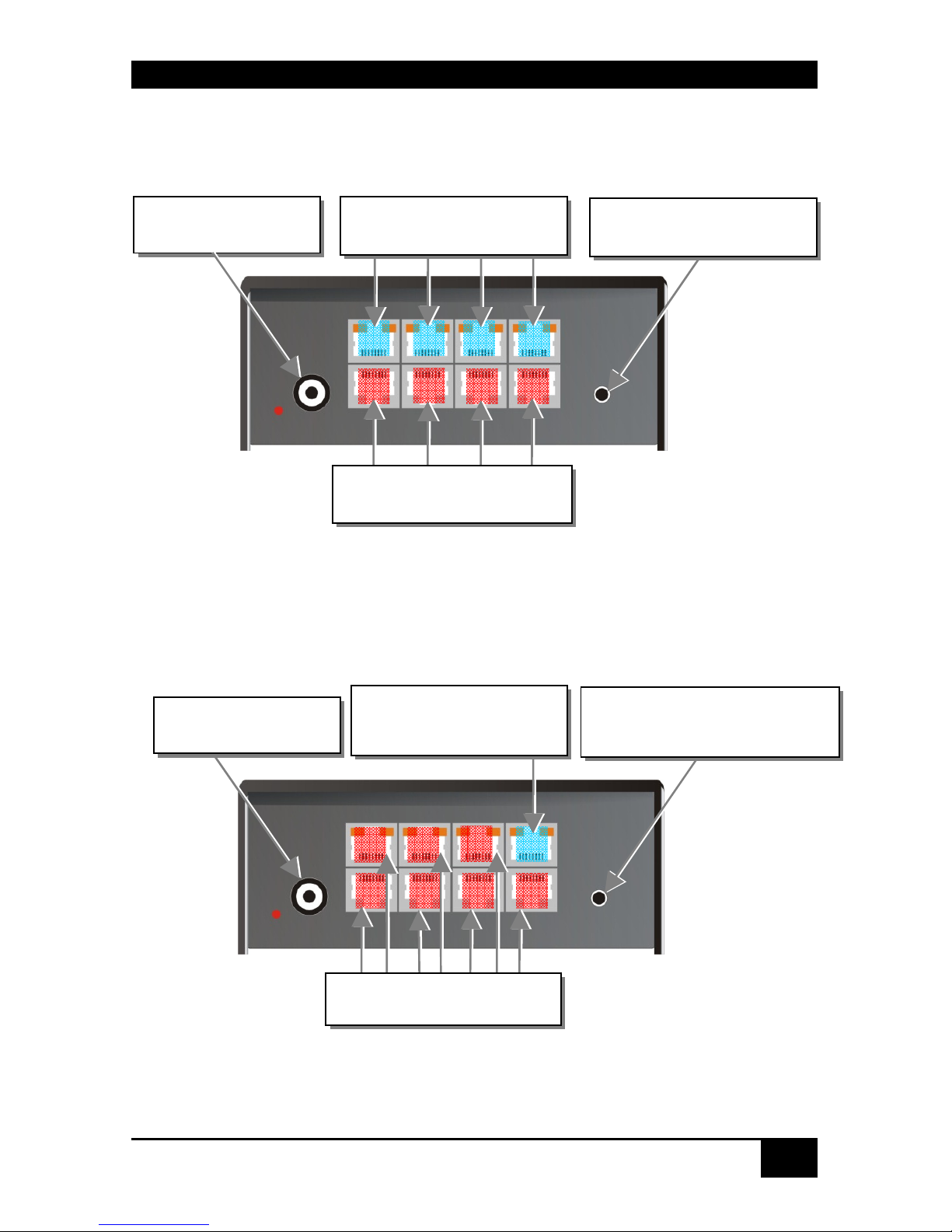
Configuration ‘Multiplex-Repeater’ – 1 Source up to 7 Displays
THOR Small Switch – as 1-to-7 Multiplex-Repeater
Configuration ‘Multiplex-Repeater’ – 2 Sources / each up to 3
Displays
THOR Small Switch – as 2x 2-to-3 Multiplex-Repeater
Connect to the THOR
Media Remote Units
Push-button, no function
in this operating mode
Push-button, no
function in this
operating mode
R
L R
R
R R
R
R
Connect to the THOR
Media Local Unit
Connect to the THOR
Media Remote Units
Connect to 5V power
supply
Connect to 5V power
supply
Connect to the THOR Media
Remote Units A
Connect to the THOR
Media Local Unit A
Connect to the THOR Media
Remote Units B
Connect to the THOR
Media Local Unit B
THOR-SSM
Rev. : 02/09/2012
35
Configuration ‘Multiplex-Repeater’ – 4 Sources on 4 Displays
THOR Small Switch – as 4x 1-to-4 Multiplex- Repeater
Configuration ‘Crosspoint-Switch’ 1 Input / 7 Outputs
THOR Small Switch – as Crosspoint-Switch 1x7
Connect to 5V power
supply
Push-button, no function in
this operating mode
L
D
Connect to the THOR KVM/
Media Local Units
Connect to the THOR KVM/
Media Remote Units
Connect to the THOR Media
Remote Units
Push-button; for the
sequential selection of pre-
programmed configurations
Connect to 5V power
supply
Connect to the THOR
Media Local Unit

THOR-SSM
36
Rev. : 02/09/2012
Configuration ‘Crosspoint-Switch’ 2 Inputs / 6 Outputs
THOR Small Switch – as Crosspoint-Switch 2x6
Configuration ‘Crosspoint-Switch’ 3 Inputs / 5 Outputs
THOR Small Switch – as Crosspoint-Switch 3x5
Push-button; for the
sequential selection of pre-
programmed configurations
Connect to 5V power
supply
Connect to the THOR Media
Local Units
Connect to the THOR Media
Remote Units
Connect to the THOR Media
Remote Units
Push-button; for the
sequential selection of pre-
programmed configurations
Connect to 5V power
supply
Connect to the THOR Media
Local Units

THOR-SSM
Rev. : 02/09/2012
37
Configuration ‘Crosspoint-Switch’ 4 Inputs / 4 Outputs
THOR Small Switch – as Crosspoint-Switch 4x4
Configuration ‘Crosspoint-Switch’ 5 Inputs / 3 Outputs
THOR Small Switch – as Crosspoint-Switch 5x3
Pushbutton; for the sequential
selection of pre-programmed
configurations
Connect to 5V power
supply
Pushbutton; for the sequential
selection of pre-programmed
configurations
Connect to 5V power
supply
Connect to the THOR Media
Local Units
Connect to the THOR Media
Remote Units
Connect to the THOR Media
Remote Units
Connect to the THOR Media
Local Units

THOR-SSM
38
Rev. : 02/09/2012
Configuration ‘Crosspoint-Switch’ 6 Inputs / 2 Outputs
THOR Small Switch – as Crosspoint-Switch 6x2
Configuration ‘Crosspoint-Switch’ 7 Inputs / 1 Output
THOR Small Switch – as Crosspoint-Switch 1x7
Connect to 5V power
supply
Pushbutton; for the sequential
selection of pre-programmed
configurations
Connect to 5V power
supply
Connect to the THOR Media
Local Units
Connect to the THOR Media
Remote Units
Connect to the THOR Media
Remote Unit
Connect to the THOR Media
Local Units
Push-button; for the
sequential selection of pre-
programmed configurations

THOR-SSM
Rev. : 02/09/2012
39
Configuration ‘Single-head KVM-Switch’
THOR Small Switch – as Single-head KVM-Switch
Configuration ‘Dual-head KVM-Switch’
THOR Small Switch – as Dual-head KVM-Switch
Push-button; for the
sequential selection of
the connected CPUs
Connect to the THOR KVM
Local Units (CPU) – Video 1
+ K/M
Connect to the THOR KVM
Remote Units (Console) –
Video 1 + K/M
Connect to 5V power
supply
Connect to the THOR KVM
Local Units (CPU)
Push-button; for the
sequential selection of the
connected PCs
Connect to the THOR KVM
Remote Unit (Console)
Connect to the THOR KVM
Local Units (CPU)
L
A2
L
B1
L
A1
L
B2
R
B
R
A
L
B3
L
A3
Connect to 5V power
supply
Connect to the THOR KVM
Local Units (Console) –
Video 2 + K/M
Connect to the THOR KVM
Local Units (CPU) – Video 2
+ K/M

THOR-SSM
40
Rev. : 02/09/2012
THOR Small Switch rear view
Serial Interface
(RS232)
Operating Mode
(DIP switch)

THOR-SSM
Rev. : 02/09/2012
41
4.2 THOR Media Extender
THOR Media Local Unit
THOR Media Remote Unit
THOR Media (+ Audio) Local Unit
To CPU: DVI
Connect to remote DVI-
monitor
Connect to local DVI-
monitor
To CPU:
DVI
Connect to local DVI-
monitor
To CPU:
Audio/serial

THOR-SSM
42
Rev. : 02/09/2012
THOR Media Remote Unit (with Audio)
THOR Media Local/ Remote Unit – rear view
THOR Media Local/ Remote Unit – rear view
Audio Out
Connect to 5V power
supply
Remote DVI- monitor
port– connect to remote
console monitor
Serial
Out
INTERCONNECT – carries video
and data signals – connect to Local/
Remote Unit with CATx- cable
Connect to 5V power
supply
INTERCONNECT – carries video
and data signals – connect to Local/
Remote Unit with fibre- cable

THOR-SSM
Rev. : 02/09/2012
43
4.3 THOR KVM Extender
THOR KVM Local Unit
THOR KVM Remote Unit
Remote keyboard/
mouse port
To CPU:
DVI- graphic card
Connect to local
DVI- monitor
Remote DVI- monitor port–
Connect to remote console
monitor
Connect to CPU:
USB

THOR-SSM
44
Rev. : 02/09/2012
THOR KVM Local/ Remote Unit – rear view
THOR KVM Local/ Remote Unit – rear view
Connect to 5V power
supply
INTERCONNECT – carries video
and data signals – connect to Local/
Remote Unit with CATx- cable
Connect to 5V power
supply
INTERCONNECT – carries video
and data signals – connect to Local/
Remote Unit with fibre- cable

THOR-SSM
Rev. : 02/09/2012
45
THOR KVM Local Unit with audio
THOR KVM Remote Unit with Audio
Audio In
To CPU: Serial
To CPU: DVI
Connect to CPU:
USB
Audio Out
Serial Out
Connect to local
DVI- monitor
Remote DVI- monitor port–
Connect to remote console
monitor
Remote keyboard/
mouse port

THOR-SSM
46
Rev. : 02/09/2012
THOR KVM Local Unit with 4x USB-HID
THOR KVM Remote Unit with 4x USB-HID
To CPU: DVI
Connect to CPU:
USB
Program
Connect to local
DVI- monitor
Remote DVI- monitor port–
Connect to remote console
monitor
Remote keyboard/
mouse port
Connect to CPU:
secondary USB
Remote secondary
USB-HID port
Programming Connect to CPU: DVI-I
Port (DVI-D or VGA)
’Eye’ for IR-RC

THOR-SSM
Rev. : 02/09/2012
47
THOR KVM Local Unit with DVI-I Input (DVI-D + VGA)
Connect to CPU:
USB
Connect to local
DVI- monitor

THOR-SSM
48
Rev. : 02/09/2012
THOR KVM Local/ Remote Unit with audio – rear view
THOR KVM Local/ Remote Unit with audio – rear view
Connect to 5V power
supply
INTERCONNECT – carries video and
data signals – Connect to Local/
Remote Unit with CATx- cable
Connect to 5V power
supply
INTERCONNECT – carries video and
data signals – Connect to Local/
Remote Unit with fibre- cable

THOR-SSM
Rev. : 02/09/2012
49
THOR KVM Dual-head Local Unit
THOR KVM Dual-head Remote Unit
Connect to CPU:
USB
Connect to CPU:
2nd DVI- graphic card
2nd local DVI- monitor port- Connect to
local console 2nd monitor
Connect to CPU:
1st DVI- graphic card
Local DVI- monitor
port- Connect to local
console monitor
2nd remote DVI- monitor
port- Connect to remote
console 2nd monitor
1st remote DVI-
monitor port– connect
to remote console 1
st
monitor
Remote keyboard/
mouse port

THOR-SSM
50
Rev. : 02/09/2012
THOR KVM Dual-Head Local Unit with 4x USB-HID
THOR KVM Dual-Head Remote Unit with 4x USB-HID
Connect to CPU:
USB
Connect to CPU:
2nd DVI- graphic card
2nd local DVI- monitor port- Connect to
local console 2nd monitor
Connect to CPU:
1st DVI- graphic card
Local DVI- monitor
port- Connect to local
console monitor
2nd remote DVI- monitor
port- Connect to remote
console 2nd monitor
1st remote DVI-
monitor port– connect
to remote console 1
st
monitor
Remote keyboard/
mouse port
Connect to CPU:
secondary USB
Remote secondary
USB-HID ports

THOR-SSM
Rev. : 02/09/2012
51
THOR KVM-Dual-head Local Unit with audio
THOR KVM Dual-head Remote Unit with audio
Audio Out
Serial Out
Remote keyboard/
mouse port
2nd remote DVI- monitor
port- Connect to remote
console 2nd monitor
1st remote DVI- monitor
port– Connect to remote
console 1st monitor
2nd local DVI- monitor
port- Connect to local
console 2nd monitor
Connect to CPU:
DVI- cable set (2nd DVI-
graphic card, audio, and
Connect to CPU:
USB
Connect to CPU:
1st DVI- graphic card
Local DVI- monitor
port- Connect to local
console monitor
To CPU:
Audio/serial

THOR-SSM
52
Rev. : 02/09/2012
THOR KVM Local Unit with 2x USB-HID + 4x USB-2.0
THOR KVM Remote Unit with 2x USB-HID + 4x USB-2.0
To CPU: DVI
Connect to CPU:
USB
Connect to local
DVI- monitor
Remote DVI- monitor port–
Connect to remote console
monitor
Remote keyboard/
mouse port
Connect to CPU:
secondary USB
4x Remote secondary
USB-2.0 port

THOR-SSM
Rev. : 02/09/2012
53
THOR KVM Dual-head, Local/ Remote Unit, with optional audio – rear view
THOR KVM Dual-head, Local/ Remote Unit, with optional audio – rear view
Connect to 5V power
supply
INTERCONNECT – carries 2nd video –
Connect to Local/ Remote Unit with
CATx- cable
INTERCONNECT – carries 1st video
and data signals – Connect to Local/
Remote Unit with CATx- cable
INTERCONNECT – carries 2nd
video – Connect to Local/
Remote Unit with fiber- cable
Connect to 5V power
supply
INTERCONNECT – carries 1st video and
data signals – Connect to Local/ Remote
Unit with CATx
-
cable

THOR-SSM
54
Rev. : 02/09/2012
5. Diagnostic
5.1 THOR Small Switch for CATx
Each THOR Small Switch is fitted with two indicator LEDs: Power and Link Status: The
Power LED is next to the Power socket. The Link Status LEDs are at the upper CATx-
connectors in the left and right upper corner. The LEDs in the left corners show the status for
the lower CATx- connectors, the right LEDs for the upper CATx- connectors.
The location of the LEDs is shown below:
Diagnostic- LEDs at THOR Small Switch for CATx
LED Appearance Diagnostics
Power LED
(Red LED)
Off
On
Device not ready
Device ready
Link Status
(Orange LED)
Off
Orange On
Orange Blinking
Green On
Green blinking
No transmission over the CATx- cable
attached local/remote unit is disconnected,
switched off or a broken cable
Connection through CATx cable is OK
Actual CPU selected by push button (only type
KVM- Switch)
active path (only type KVM- Switch)
the active path has no connection through the trunk
cable (only type KVM- Switch)
Diagnostic LED
Power
Diagnostic LED
Link Status
Lower connector
Diagnostic LED
Link Status
Upper connector

THOR-SSM
Rev. : 02/09/2012
55
5.2 THOR Small Switch for CATx
Each THOR Small Switch is fitted with two indicator LEDs: Power and Link Status: The
Power LED is next to the Power socket. The Link Status LED is located between the lower
and upper fiber connector. The LED shows the status for the lower interconnection, the
____LED for the upper interconnection.
The position of the LEDs is shown below
:
Diagnose- LEDs on THOR Small Switch for Fiber
LED Appearance Diagnostics
Power LED
(Red LED)
Off
On
Device not ready
Device ready
Link Status
(Orange LED)
Off
Orange On
Orange Blinking
Green On
Green Blinking
No transmission over the fiber- cable
attached local/remote unit is disconnected, switched
off or a broken interconnect cable
Connection through fiber cable is OK
Actual CPU selected by push button (only type
KVM- Switch)
active path (only type KVM- Switch)
the active path has no connection through the trunk
cable (only type KVM- Switch)
Diagnostic LED
Power
Diagnostic LED
Link Status
Lower connector
Diagnostic LED
Link Status
Upper connector

THOR-SSM
56
Rev. : 02/09/2012
5.3 THOR Media/ KVM Extender
Each THOR Extender is fitted with four indicator LEDs: Power, Video OK, Data Error, and
Link Status: The Power LEDs are next to the power socket.
The location of the LEDs is shown below:
Diagnostic- LEDs at THOR KVM/ Media Extender
LED Appearance Diagnostics
Power LED
(Red LED)
Off
On
Device not ready
Device ready
Video Okay
(Green LED)
Off
On
No or invalid video signal detected
Device ready
Link Status
(Green LED)
blinking
On
No CATx- connection
Device ready
Data Error
(Green LED)
Off
blinking / On
Device ready
Errors through data transmission over CATx- cable
(cable too long, too high attenuation or too much
EMI interference)
Diagnostic LED
Power
Diagnostic LED
Video OK
Diagnostic LED
Data Error
Diagnostic LED
Link Status

THOR-SSM
Rev. : 02/09/2012
57
6. Service Setup
6.1 THOR Small Switch for CATx
Normally, it is only necessary to make adjustments during installation.
In order to make these adjustments, you do not have to open the THOR Small Switch. All
settings can be made from the outside using the Operating Mode Selector (DIP switch).
By selecting a new operating mode, the allocation of inputs
and outputs may be changed. In doing so, it is possible to
interconnect two transmitters: this may damage the
connected equipment.
The location of the operating mode selector (DIP switch) is shown below:
For the selection of a new operating mode:
1. Switch off the THOR Small Switch.
2. Select a new operating mode according to following table.
By selecting a new operating mode, the allocation of inputs
and outputs may be changed. In doing so, it is possible to
interconnect two transmitters: this may damage the
connected equipment.
3. Power up the device.
Operating Mode
Selector

THOR-SSM
58
Rev. : 02/09/2012
Operating Mode Selection
Operating Mode Selector
Operating Mode
Selector
Operating Mode
Multiplex- Repeater: The signal(s) coming from the Local Unit is
(are) equalized (and distributed) and extended over further 140m.
An incoming DVI
(+audio) signal is
distributed and
extended on up to 7
outputs.
Two incoming DVI
(+audio) signals are
distributed and
extended each up to 3
outputs.
4 incoming DVI
(+audio) signals are
extended.
Crosspoint Switch: Every port can either be an input (to a Local Unit)
or an output (to a Remote Unit). Each connection input/output is
possible.
1x IN / 7x OUT
The signals of one
source can be
switched to up to 7
displays.
2x IN / 6x OUT
The signals of 2
sources can be
switched to up to 6
displays.
3x IN / 5x OUT
The signals of 3
sources can be
switched to up to 5
displays.
4x IN / 4x OUT
The signals of 4
sources can be
switched to up to 4
displays.
5x IN / 3x OUT
The signals of 5
sources can be
switched to up to 3
displays.
6x IN / 2x OUT
The signals of 6
sources can be
switched to up to 2
displays.
Switch setting
Down
Switch setting
Up
Switch setting
Extraneous

THOR-SSM
Rev. : 02/09/2012
59
7x IN / 1x OUT
The signals of 7
sources can be
switched to one
display.
KVM- Switch 1/7 Single-head: Up to 7 CPUs (up to 49 with cascaded
application) can be operated from one console.
KVM- Switch 1/3 Dual-head: Up to 3 CPUs with Dual-head graphic
card (up to 9 with cascaded application) can be operated from one
console.
Standard operating mode
Reset the THOR Small Switch to default settings (Factory Reset):
1. switch power off
2. set the DIP- switch
3. switch power on, the device is resetting
4. switch power off
5. set the DIP- switch back
6. switch power on - done
Operating Mode after Reset/ Power ON: After reset, the respective
DEFAULT-mode is selected.
Operating Mode after Reset/ Power ON: After reset, the previous
mode before reset or power off is selected.
Master: In a cascaded application in KVM- switch mode, the device is
‘Master’– i.e. it is on highest level within the tree structure, seen from
the Remote Unit.
Slave: In a cascaded application in KVM- switch mode, the device is
‘Slave’– i.e. it is on second level within the tree structure, seen from
the Remote Unit.

THOR-SSM
60
Rev. : 02/09/2012
Connection of THOR Control External Switching Device
(Accessories)
Using the THOR Control External Switching Device you can start to realize the
switching possibilities of the THOR Small Switch...
The THOR Control External Switching Device is mainly a small media control unit
which allows programming and processing the switching functions of the THOR via
Infrared Remote Control.
Additionally, this device has 8 digital inputs to recall macro functions (CP-mode) or for
direct switching to a CPU (KVM- mode). Also, there are 8 LED driving outputs to
monitor the last selected CPU or the number of the last processed macro.
THOR Control External Switching Device with related Infrared Remote Control
This device is powered from the THOR. To provide power, an internal jumper must be
set accordingly.

THOR-SSM
Rev. : 02/09/2012
61
To set the jumper for powering the THOR Control External Switching Device, you need to
open the THOR Small Switch Device. To open the unit, unscrew the Philips screws at the
bottom of the device. Carefully remove the lower and upper shells of the case.
The jumper is located as shown in the following figure:
Plug the jumper on the two pins. Then close the devices and secure it by screws. Now you
can connect your THOR Control External Switching Device.
Fastening
screws on the
base
Fastening
screws on the
base

THOR-SSM
62
Rev. : 02/09/2012
6.2 THOR Media/ KVM Extender
For standard applications, you shouldn't need to make any adjustments to your THOR Small
Switch Media/KVM Extender. However, in certain circumstances, you may need to open the
Local Unit and/or the Remote Unit. To open one of the units, unscrew the Philips-type screws
at both sides at the bottom of the device. Unscrew the UNC type screws on each side of the
monitor connectors. Carefully displace the lower and upper shells of the case.
The following diagnostic LEDs are used to indicate configuration changes:
The diagnostic LED ‘Video OK’ is located at the Local Unit between the both DVIconnectors
The diagnostic LED ‘Video OK’ is located near to the CATx- connectors
Diagnostic LED
Video OK
Fastening
screws on the
base
Fastening
screws on the
base
Diagnostic LED
Link Status
(CATx)
Diagnostic LED
Link Status
(fiber)

THOR-SSM
Rev. : 02/09/2012
63
6.3 Setup at the Local Unit
After unscrewing and opening the upper shell, please place the device with the CATxconnectors to the right and the monitor connectors to the left.
The main PCB then will look like this:
Use the diagram to locate jumpers.
DDC / color depth
You can select whether the DDC information is taken from internal DDC table,
from the local monitor or downloaded from the remote monitor and stored in
internal table.
DDC JP1 JP2
From internal table
(default)
From local monitor
Load the DDC information from the
remote monitor into the internal DDC
table (see also below: loading the DDC
information from the remote monitor into
the internal DDC table)
JP1, JP2, JP3

THOR-SSM
64
Rev. : 02/09/2012
Loading the DDC Information from the Remote Monitor into the internal
DDC Table
To load the DDC Information from the Remote Monitor into the internal DDC Table,
please proceed with the following steps:
• Power up the CPU, the Local Unit, the Remote (cables to the CPU connected) and the
Monitor
• Pull the Monitor Cable(s) from the Remote Unit (Dual-head devices: BOTH Monitors!)
• Switch ON the Monitor(s) (if switched OFF, Dual-head devices: BOTH Monitors!)
• Plug the Video Cable of the Remote Monitor(s) into the remote unit (Remote and Local
Unit powered! - Dual-head devices: BOTH Monitors!)
• The DDC Information of the Remote Monitor(s) is read automatically, transferred to the
Local Unit and stored into the DDC-EPROM
• After a successful programming of the DDC EPROM, the Video-OK LED at the Local
Unit will blink rapidly for approx. 1 second
• Done
Selection of Color depth
You can select whether 16/24Bit AUTOSELECT colors (=64K/16M colors) are transmitted
(default) or 24Bit colors (=16M colors). AUTOSELECT means that as far as the screen
content allows high data compression, 24Bits are transmitted. When the video data is it too
high of a rate, the colors are automatically reduced to 16Bit. This is auto-selected in each line
of the screen picture at any time. This mode makes the best compromise between speed and
color depth.
Please select 24Bit if you want to have, under all circumstances, the highest color rate- but
potentially with reduced frame rates.
Color depth JP3
16Bit/24Bit AUTOSELECT, color depth depending on
actual screen content (default)
24Bit

THOR-SSM
Rev. : 02/09/2012
65
6.4 Setup at the Remote Unit
After unscrewing and opening the upper shell, please place the device with the CATxconnectors to the right and the monitor connector to the left.
The main PCB then will look like this:
Use the diagram to locate jumpers.
Selecting the moment of switching to the next frame
The transmission of screen data is not synchronous to the screen change of the graphic card.
Normally, the transmission is terminated when a frame is displayed on the screen. If the
device switches to the new frame during HSYNC, the displaying period of the old frame, you
may see horizontal screen breaks at the moment of switching (default). Alternatively, you can
set up the units to idle until the actual frame is displayed completely, during VSYNC. Using
this method, the number of frames per second transmitted is lower.
Moment to switch
JP3 Behavior
Switching during HSYNC
(default)
Higher frame rate but (possibly) horizontal breaks
detectable
Switching during VSYNC
Lower frame rate, no horizontal breaks detectable
but (possibly) stepping pictures
JP1, JP2, JP3

THOR-SSM
66
Rev. : 02/09/2012
7. Operating Modes
7.1 Multiplex- Repeater
The DVI signals (and optional audio) originating from a signal source are distributed and
extended – depending on the configuration – on up to 7 equivalent outputs. The signals of the
CPU (signal source) are transmitted to a Local Unit which is attached to the THOR Small
Switch by CATx cables. The transmission between the THOR Small Switch and up to 7
Remote Units is also done by CATx cables. Optionally, instead of Remote Units, further
THOR Small Switches can be installed for a second stage of distributors. Further Remote
Units can be connected to the second stage repeaters, allowing up to 49 display units to be
controlled.
The distance between a Local Unit and THOR Small Switch or between a THOR Small
Switch and Remote Unit or between two THOR Small Switches may amount to, in each case,
up to 140m allowing installations in distributed applications.
Configuration ‘Multiplex-Repeater’ –
1 Source up to 7 Displays
A single signal from a Local Unit is distributed on up to 7 outputs and transferred over
CATx- cables on up to 7 Remote Units. Using a second stage of Multiplex Repeaters, up to
49 monitors can be supplied with video (and optionally audio).
Connect to the THOR
Media Remote Units
Push-button, no function
in this operating mode
R
L R
R
R R
R
R
Connect to the THOR
Media Local Unit
Connect to the THOR
Media Remote Units
Connect to 5V power
supply

THOR-SSM
Rev. : 02/09/2012
67
Configuration ‘Multiplex-Repeater’ –
2 Sources, each up to 3 displays
Two different signals from two Local Units are each distributed to 3 outputs and transferred
over CATx- cables to 3 Remote Units. Using a second stage of Multiplex Repeaters up to 2x9
(2x21) monitors can be supplied with video (and optionally audio).
Configuration ‘Multiplex-Repeater’ –
4 Sources on 4 Displays
Four different signals from four Local Units are transferred over CATx- cables to one
equivalent Remote Unit. This allows an extension of the cable length if the usual 140m
distance by CATx- cables is not sufficient.
Connect to 5V power
supply
Input to the THOR Media
Local Unit A
Pushbutton, no
function in this
operating mode
Outputs to the THOR Media
Remote Units A
Outputs to the THOR Media
Remote Units B
Input of the THOR Media
Local Unit B
Connect to 5V power
supply
Push-button, no function in
this operating mode
L
B
L
D
Connect to the THOR KVM/
Media Local Units
Connect to the THOR KVM/
Media Remote Units

THOR-SSM
68
Rev. : 02/09/2012
Example Applications:
A video/audio source is switched over the THOR Small Switch to 4 different
screens/loudspeakers. Additionally a control monitor can be attached at the Local Unit.

THOR-SSM
Rev. : 02/09/2012
69
Three cascaded THOR Small Switches each with a local second screen and 13 screens
for presentations.

THOR-SSM
70
Rev. : 02/09/2012
Indicator LEDs
The following indicator LEDs are used in the ‘Multiplex-Repeater’ operating mode:
Meaning of the diagnostic LEDs:
LED Appearance Diagnostics
Power LED
(Red LED)
Off
On
Device not ready
Device ready
Link Status
(Orange LED)
Off
Orange On
No transmission over the CATx- cable
attached local/remote unit is disconnected,
switched off or a broken interconnect cable
Connection through CATx cable is OK
Diagnostic LED
Link Status
Lower connector
Diagnostic LED
Link Status
Upper connector

THOR-SSM
Rev. : 02/09/2012
71
Setup
There are no other setups available in ‘Multiplex-Repeater’ operating mode.
Operation
In operating mode ‘Multiplex-Repeater’ the following operations are possible:
By serial interface
You can find the allocation of the serial interface under “Serial Interface” on page 145. A
standard cable (RJ45 / DB9) to the CPU is included in delivery.
For the complete communication protocol and an explanation of the control characters please
see Appendix E: Protocol for command mode
For communication, please set up the format of the serial data communication to:
115.2K, 8, 1, NO
(115.2 KBAUD, 8 Data bit, 1 Stop bit, NO parity)
Control commands
In the ‘Multiplex-Repeater’ operating mode, the following commands are allowed:
• STX, 0x40, 0x80, ETX Acknowledgment of the system information
• STX, 0x54, ETX Reset of the Multiplex- Repeater
Serial Interface
(RS232)

THOR-SSM
72
Rev. : 02/09/2012
7.2 Crosspoint- Switch
In “Crosspoint- Switch" operating mode, each port of the THOR Small Switches can be used
either as an input (to a Local Unit) or as an output (to a Remote Unit). Thus any combinations
between 1x input/7x output and 7x input/1x output are possible. The device offers no channel
monitoring in this mode so you must ensure the correct connection of the CATx- cables.
Incorrect cabling may switch two inputs or two outputs to each other and this could damage
your equipment!
An incoming DVI (+audio) signal can be switched and extended to one or more outputs
allowing you to output the signal to several displays at the same time (broadcast function).
The signal from the CPU (signal source) is transmitted over a Local Unit and CATx- cables
to the THOR Small Switch. From the THOR Small Switch, the transmission continues over
CATx- cables to up to 7 Remote Units. Alternatively, a further THOR Small Switch (slave)
can be used between the first stage switch and further Remote Units. Therefore, complex
switching modes can be achieved.
During operation, the allocation of ports as input or output is fixed. Devices must be attached
according to the following diagrams.
The distance between a Local Unit and THOR Small Switch or between a THOR Small
Switch and Remote Unit or between two THOR Small Switches may amount to 140m;
allowing installations in distributed applications.
The control of the switching status is made by the integrated, serial interface. Switching
commands can be converted directly here. Switching combinations can be additionally stored
as macros. These can be called up with a short command or by using the push-button on the
device. Using the serial interface, macros can be selected directly; with the push-button, the
macros are successively activated.

THOR-SSM
Rev. : 02/09/2012
73
Configuration ‘Crosspoint-Switch’
1 Input / 7 Outputs
The signal of a Local Unit is switched on up to 7 outputs and transmitted over CATx- cables
on up to 7 Remote Units. Optionally, a further THOR Small Switch can be inserted for a
second switching stage.
Configuration ‘Crosspoint-Switch’
2 Inputs / 6 Outputs
The signals of 2 Local Units are switched on up to 6 outputs and transferred over CATxcables to 6 Remote Units. Optionally, an additional THOR Small Switch can be inserted for a
second switching stage.
Connect to the THOR Media
Remote Units
Push button; for the
sequential selection of pre-
programmed configurations
Connect to 5V power
supply
Connect to the THOR
Media Local Unit
Push button; for the
sequential selection of pre-
programmed configurations
Connect to 5V power
supply
Connect to the THOR Media
Local Units
Connect to the THOR Media
Remote Units

THOR-SSM
74
Rev. : 02/09/2012
Configuration ‘Crosspoint-Switch’
3 Inputs / 5 Outputs
The signals of 3 Local Units are switched on up to 5 outputs and transferred over CATxcables to 5 Remote Units. Optionally, an additional THOR Small Switch can be inserted for a
second switching stage.
Configuration ‘Crosspoint-Switch’
4 Inputs / 4 Outputs
The signals of 4 Local Units are switched on up to 4 outputs and transferred over CATxcables to 4 Remote Units. Optionally, an additional THOR Small Switch can be inserted for a
second switching stage.
Connect to the THOR Media
Remote Units
Push button; for the
sequential selection of pre-
programmed configurations
Connect to 5V power
supply
Connect to the THOR Media
Local Units
Push button; for the
sequential selection of pre-
programmed configurations
Connect to 5V power
supply
Connect to the THOR Media
Local Units
Connect to the THOR Media
Remote Units

THOR-SSM
Rev. : 02/09/2012
75
Configuration ‘Crosspoint-Switch’
5 Inputs / 3 Outputs
The signals of 5 Local Units can be switched on up to 3 outputs (also on several) and be
transferred over CATx- cables on up to 3 Remote Units. Optionally, an additional THOR
Small Switch can be inserted for a second switching stage.
Configuration ‘Crosspoint-Switch’
6 Inputs / 2 Outputs
The signals of 6 Local Units can be switched on up to 2 outputs (also on several) and be
transferred over CATx- cables on up to 2 Remote Units. Optionally, an additional THOR
Small Switch can be inserted for a second switching stage.
Push button; for the
sequential selection of pre-
programmed configurations
Connect to 5V power
supply
Connect to the THOR Media
Remote Units
Connect to the THOR Media
Local Units
Pushbutton; for the sequential
selection of pre-programmed
configurations
Connect to 5V power
supply
Connect to the THOR Media
Local Units
Connect to the THOR Media
Remote Units

THOR-SSM
76
Rev. : 02/09/2012
Configuration ‘Crosspoint-Switch’
7 Inputs /1 Output
The signals of 7 Local Units can be switched to one output and be transferred over CATxcables to one Remote Unit. Optionally, an additional THOR Small Switch can be inserted for
a second switching stage.
Connect to 5V power
supply
Connect to the THOR Media
Remote Unit
Connect to the THOR Media
Local Units
Push-button; for the
sequential selection of pre-
programmed configurations

THOR-SSM
Rev. : 02/09/2012
77
Example Application:
Three video sources are switched over the THOR Small Switch on four different screens.

THOR-SSM
78
Rev. : 02/09/2012
Setup
The following configurations are possible in the ‘Crosspoint-Switch’ operating mode:
Operating mode after Reset/Power ON
After a reset the respective DEFAULT- Mode is selected:
1x7: Input I1 is switched to Output O1
2x6: I1 to O1 and I2 to O2
3x5: I1 to O1, I2 to O2 and I3 to O3
4x4: I1 to O1, I2 to O2, I3 to O3 and I4 to O4
5x3: I1 to O1, I2 to O2 and I3 to O3
6x2: I1 to O1 and I2 to O2
7x1: I1 to O1
Operating mode after Reset/Power ON: After reset, the previous
mode before reset or power OFF is selected.

THOR-SSM
Rev. : 02/09/2012
79
Indicator LEDs
The following indicator LEDs are used in the ‘Crosspoint-Switch’ operating mode:
Meaning of the diagnostic LEDs:
LED Appearance Diagnostics
Power LED
(Red LED)
Off
On
Device not ready
Device ready
Link Status
(Orange LED)
Off
Orange On
Green blinking
No transmission over the CATx- cable
attached local/remote unit is disconnected,
switched off or a broken interconnect cable
Connection through CATx cable is OK
Actually selected macro
Diagnostic LED
Link Status
Lower connector
Diagnostic LED
Link Status
Upper connector

THOR-SSM
80
Rev. : 02/09/2012
Operation
The following operations are possible in the ‘Crosspoint-Switch’ operating mode:
a) By push button:
With the first key press, the macro display is switched on. The LED with the number of the
active selected macro flashes green. With each key press, the display will switch to the next
LED. With each key press, the next macro stored in the device is called and the programmed
switching configuration is loaded. The macro will only be executed if the push button is not
operated for longer than 2 seconds. If the push button is released for longer than 2 seconds,
the operation is cancelled. The selection of a not (yet) programmed macro will be interpreted
as a reset (see below).
b) By serial interface
You can find the allocation of the serial interface under “Serial Interface” on page 145. A
standard cable RJ45 / DB9 to the CPU is included in delivery.
For the complete communication protocol and an explanation of the control characters please
see Appendix E: Protocol for command mode
Push-Button
Serial Interface
(RS232)

THOR-SSM
Rev. : 02/09/2012
81
For communication please set up the format of the serial data communication to:
115.2K, 8, 1, NO
(115.2 KBAUD, 8 Data bit, 1 Stop bit, NO parity)
Control commands
In the ‘Crosspoint- Switch’ operating mode the following control commands are allowed:
• STX, 0x40, 0x80, ETX Acknowledgement of the system info
• STX, 0x45, ETX Reset on factory settings
• STX, 0x54, ETX Reset the Crosspoint- Switch
• STX, 0x47, <Rem-No>, <Loc-Nr>, ETX
S
witch a single (remote-)output to
a (local-) input
• STX, 0x48, <Rem-No>, ETX
S
witch off a single (remote-)output
• STX, 0x52, ETX
Switch off all local-/ remote-connections
• STX, 0x66, 0x80, <Macro-No>, ETX
S
ave switching status to macro
• STX, 0x67, 0x80, <Macro-No>, ETX
L
oad switching status from macro
where:
<Rem-No> 7Bit date 1 to 7
<Loc-No> 7Bit date 1 to 7
<Macro-No> 7Bit date 1 to 8
Examples:
STX, 0x54, ETX Reset the switch and set the connections as a function of
SW7 (see above)
STX, 0x40, 0x80, ETX Read the system info (version number) from the switch
STX, 0x52, ETX
S
witch off all local-/ remote- connections
STX, 0x47, 0x84, 0x81, ETX Switch (remote-)output 04 to (local-)input 01
STX, 0x47, 0x85, 0x81, ETX Switch (remote-)output 05 to (local-)input 01 ((remote-)
output 04 and 05 show the same picture now!)
STX, 0x47, 0x86, 0x81, ETX Switch (remote-)output 06 to (local-)input 01 ((remote-)
output 04 - 06 show the same picture now!)
STX, 0x47, 0x87, 0x81, ETX Switch (remote-)output 07 to (local-)input 01 ((remote-)
output 04 - 07 show the same picture now!)
STX, 0x66, 0x80, 0x81, ETX Saves active switching status as macro 1
STX, 0x52, ETX Opens all connections (all monitors are without picture)
STX, 0x67, 0x80, 0x81, ETX Call macro 1: (remote-)output 04 - 07 show the same
picture of (local-)input 01 now
STX, 0x48, 0x84, ETX Open the connection between (remote-)output 04 and the
equivalent (local-)input (only monitor 05 – 07 show the
picture)

THOR-SSM
82
Rev. : 02/09/2012
c) By the attached keyboard
Since Firmware Revision dated Nov-20, 2009 you can also switch the Console 1 (which is
connected to Remote Unit 1) using the attached keyboard.

THOR-SSM
Rev. : 02/09/2012
83
7.3 Single-head KVM- Switch
Using one console (monitor, keyboard and mouse) up to 7 CPUs can be controlled remotely.
The distances between the CPU and THOR Small Switch and between THOR Small Switch
and console may amount to 140m.
The switching between the CPUs can be carried out at the attached keyboard, push-button at
the device or over the serial interface.
Cascading of the THOR KVM- Switch in two stages allows up to 49 CPUs to be addressed.
In addition to the DVI- signals and USB for keyboard/mouse, bi-directional stereo-audio +
serial (RS232/V24) data can be transferred by appropriate Local/ Remote Units.
Configuration ‘Single-head KVM- Switch’
Connect to Local Unit
at CPU7
Connect to Local Unit
at CPU3
Connect to Local Unit
at CPU5
Connect to Local Unit
at CPU2
Connect to Local Unit
at CPU1
Connect to Local Unit
at CPU4
Connect to Local Unit
at CPU6
Connect to console
(Remote Unit)

THOR-SSM
84
Rev. : 02/09/2012
Example Application:
Four CPUs are switched over the THOR Small Switch to one console.

THOR-SSM
Rev. : 02/09/2012
85
Setup
In ‘Single-head- KVM- Switch’ operating mode the following setups are possible:
Master/Slave function
The device is Master (default status: it is either the exclusive device in
the system, or if THOR KVM Switches are cascaded, it is on the
highest level (directly after the console).
The device is Slave: if THOR KVM Switches are cascaded, it is on
second level (directly after the Local Units).
Operating mode after Reset/Power ON
After a reset, the DEFAULT- Mode is selected:
The console (Remote Unit) is switched to input 1 (Local Unit at
CPU1).
After reset, the previous mode before reset or power OFF is selected.

THOR-SSM
86
Rev. : 02/09/2012
Indicator LEDs
These are the indicator LEDs in the ‘Single-head- KVM- Switch’ operating mode:
Meaning of the diagnostic LEDs:
LED Appearance Diagnostics
Power LED
(Red LED)
Off
On
Device not ready
Device ready
Link Status
(Orange LED)
Off
Orange On
Orange Blinking
Green On
Green blinking
No transmission over the CATx- cable
attached local/remote unit is disconnected,
switched off or a broken interconnect cable
Connection through CATx cable is OK
Actual CPU selected by push button (only type
KVM- Switch)
active path (only type KVM- Switch)
the active path has no connection through the trunk
cable (only type KVM- Switch)
Diagnostic LED
Link Status
Lower connector
Diagnostic LED
Link Status
Upper connector

THOR-SSM
Rev. : 02/09/2012
87
Operation
The following operations are possible in the operating mode ‘Single-head KVM- Switch’:
a) By push-button:
The device switches to the next channel with each key press. The changeover will only be
executed if the push-button is not operated for longer than 2 seconds. With each key press,
the display will switch to the next channel as indicated by a rapidly blinking LED. If the last
channel is reached, the device will cycle to the first channel.
b) By serial interface
You can find the allocation of the serial interface under “Serial Interface” on page 145. A
standard cable (RJ45 / DB9) to the CPU is included in delivery.
For the complete communication protocol and an explanation of the control characters please
see Appendix E: Protocol for command mode
For communication please set up the format of the serial data communication to:
115.2K, 8, 1, NO
(115.2 KBAUD, 8 Data bit, 1 Stop bit, NO parity)
Push-button
Serial Interface
(RS232)

THOR-SSM
88
Rev. : 02/09/2012
Control commands
In Single-head KVM- Switch operating mode, the following control commands are allowed:
• STX, 0x40, 0x80, ETX Acknowledgement of the system info
• STX, 0x45, ETX Reset on factory settings
• STX, 0x54, ETX Reset the Crosspoint- Switch
• STX, 0x4F, 0x81, < Loc-No>, ETX
S
witch (local-)input to (remote-)output, the
existing connection is disconnected at the
same time
where:
< Loc-No> 7Bit date 1 to 7
Examples:
STX, 0x54, ETX Reset the switch and set the connections as a function of
SW7 (see above)
STX, 0x40, 0x80, ETX Read the system info (version number) from the switch
STX, 0x4F, 0x81, 0x84, ETX Switch console (Remote Unit) to (Local Unit) CPU 4
STX, 0x4F, 0x81, 0x85, ETX Switch console (Remote Unit) to (Local Unit) CPU 5
(existing connection to CPU 4 is disconnected)
STX, 0x54, ETX Reset the switch and set the connections as a function of
SW7 (see above)

THOR-SSM
Rev. : 02/09/2012
89
c) By the attached keyboard
By executing a ‘hot-key-sequence', the system is shifted into a command mode. Now CPUs
can be selected from the attached keyboard. Access to a switch in the second level (slave) is
also possible. To show that the command mode is active, all three status LEDs on the
keyboard flash rapidly. Press <ESC> to exit the command mode.
User commands
The input of upper/lower case letters does not matter.
<Key1>+<Key2>+ … means that all keys must be pressed at
the same time
<Key1>, <Key2>, … means that the keys must be pressed
successively
The device is designed to work at up to two levels. In command mode, all commands are sent
to the master and/ or the only device. For further extensions, input the port number prefixed
with a “0”.
For fast switching within one level (master level / slave level) the direct selection of a port is
possible by simultaneously pressing <SHIFT>+<Port-No> without <RETURN>.

THOR-SSM
90
Rev. : 02/09/2012
Call of the command mode (since firmware dated Nov-20, 2009)
• <CTRL> + <SHIFT> + <I>
Enter the command mode(default-setting)
• <ESC>
Exit the command mode
Change of the initialization-string (since Nov-20, 2009)
• <CTRL> + <SHIFT> + <C>, <x>, <RETURN>
Change of the initialization-string for the command mode (with x = number of
the initialization-string; delivery status = 1)
1: <CTRL> + <SHIFT> + <I> simultaneous
2: <Scroll lock>, <Scroll lock> press twice rapidly
3: left <SHIFT>, left <SHIFT> press twice rapidly
4: left <CTRL>, left <CTRL> press twice rapidly
5: left <ALT>, left <ALT> press twice rapidly
6: right <ALT>, right <ALT> press twice rapidly
7: left <CTRL> + right <CTRL> simultaneous
8: left <CTRL> + <SHIFT> + right <CTRL> + <SHIFT> simultaneous
9: left <CTRL> + <ALT> + right <CTRL> simultaneous
Call of the command mode (since Nov-20, 2009)
• Double-click <LEFT SHIFT>
Enter the command mode (default-setting)
• <ESC> Exit the command mode
Change of the initialization-string (since Nov-20, 2009)
<CTRL> + <SHIFT> + <C>, <x>, <RETURN>
Change of the initialization-string for the command mode (with x = number of the
initialization-string; delivery status = 3)
1: <CTRL> + <SHIFT> + <I> simultaneous
2: Double-click < Scroll lock >
3: Double-click <LEFT SHIFT>
4: Double-click < LEFT CTRL>
5: Double-click < LEFT ALT>
6: Double-click <RIGHT SHIFT>
7: Double-click < RIGHT CTRL>
8: Double-click < RIGHT ALT>

THOR-SSM
Rev. : 02/09/2012
91
Instructions within the command mode
Selection of the control level
• <M> or <m>
The following commands are executed by the ‘Master’ (default after call of the
command mode)
• <S> or <s>
The following commands are executed by the actively connected ‘Slave’
Direct selection of ports
• <SHIFT> + <x>
Switch the selected device (through <M> or <S>) on port x (with x = number of
the port) – Caution! Applies only to the selected level!
• <x>, <RETURN>
or
• <0>, <x>, <RETURN>
Switch the Remote Unit (console) to the Local Unit 0x (the port 0x) (with x =
number of the port) – Caution! Applies only to the selected level!
• <M>, <x>, <S>, <y>, <RETURN>
or
• <M>, <0>, <x>, <S>, <0>, <y>, <RETURN>
(Only in cascaded applications!) Switch the master to port 0x and the attached
slave on port 0y (with x and y = number of the ports) - Caution! Afterwards the
slave is the selected level!
Sequential selection of ports (depending on the selected control
level)
• <> (arrow key right)
Switch the console to the next port. After reaching the last port, the first port
will be selected.
• <> (arrow key left)
Switch the console to the previous port. After reaching the first port, the last
port will be selected.
• <> (arrow key up)
Switch the console (bypassing unoccupied ports) to the next port. After
reaching the last port, the first port will be selected.

THOR-SSM
92
Rev. : 02/09/2012
• <> (arrow key down)
Switch the console (bypassing unoccupied ports) to the previous port. After
reaching the first port, the last port will be selected
• <BACKSPACE>
Switches back to the last viewed channel. Allows you to switch rapidly between
two channels.
where:
x ASCII digits ‚1’ to ‚7’
y ASCII digits ‚1’ to ‚7’
Examples:
<CTRL> + <SHIFT> + <I> Call the command mode
<SHIFT> + <3> Switch immediately to port 3 (after call the master is
selected)
<M2S5>, <RETURN> Switch the master to port 2 and the slave to 5
<3>,<RETURN> Switch the slave to port 3 (because the slave was
selected in the command before)
<BACKSPACE> Switch the slave back to port 5
<M> Selection of the master level
<SHIFT> + <5> Switch (the master) immediately to port 5
<BACKSPACE> Switch the master back to port 2
<ESC> Exit command mode

THOR-SSM
Rev. : 02/09/2012
93
7.4 Dual-head KVM- Switch
From one console (2x monitor, keyboard and mouse), you can remotely control up to 3 CPUs.
The distances between the CPU and THOR Small Switch and between THOR Small Switch
and console may amount to 140m.
The switching between the CPUs can be carried out from the attached keyboard, push-button
at the device, or over the serial interface.
You can cascade THOR KVM- Switches in two stages for all applications, allowing up to 9
dual-head CPUs to be addressed.
In addition to the DVI- signals and USB for keyboard/mouse, bi-directional stereo-audio +
serial (RS232/V24) data can be transferred by the appropriate Local/ Remote Units.
Configuration of ‘Dual-head KVM- Switch’
Push-button; for the
sequential selection of
the connected CPUs
Connect to the THOR KVM
Local Units (CPU) – Video 1
+ k/m
Connect to the THOR KVM
Remote Units (Console) –
Video 1 + k/m
L
A2
L
B1
L
A1
L
B2
R
B
R
A
L
B3
L
A3
Connect to 5V power
supply
Connect to the THOR KVM
Local Units (Console) –
Video 2 + k/m
Connect to the THOR KVM
Local Units (CPU) – Video 2
+ k/m

THOR-SSM
94
Rev. : 02/09/2012
Example Application:
Three CPUs with dual-head graphic cards and local consoles switched over the THOR
Small Switch to one console.

THOR-SSM
Rev. : 02/09/2012
95
Setup
In the ‘Dual-head- KVM- Switch’ operating mode the following setups are possible:
Master/Slave function
The device is master (default status): it is either the exclusive device in
the system, or if THOR KVM Switches are cascaded, it is on highest
level (directly after the console).
The device is slave: if THOR KVM Switches are cascaded, it is on
second level (directly after the Local Units).
Operating mode after Reset/Power ON
After a reset the DEFAULT- Mode is selected:
The console (Remote Unit) is switched to input 1 (Local Unit at
CPU1).
After reset the previous mode before reset or power OFF is selected.

THOR-SSM
96
Rev. : 02/09/2012
Indicator LEDs
In the ‘Dual-head- KVM- Switch’ operating mode, the following indicator LEDs are used:
Meaning of the diagnostic LEDs:
LED Appearance Diagnostics
Power LED
(Red LED)
Off
On
Device not ready
Device ready
Link Status
(Orange LED)
Off
Orange On
Orange Blinking
Green On
Green blinking
No transmission over the CATx- cable
attached local/remote unit is disconnected,
switched off or a broken interconnect cable
Connection through CATx cable is OK
Actual CPU selected by push button (only type
KVM- Switch)
active path (only type KVM- Switch)
the active path has no connection through the trunk
cable (only type KVM- Switch)
Diagnostic LED
Link Status
Lower connector
Diagnostic LED
Link Status
Upper connector

THOR-SSM
Rev. : 02/09/2012
97
Operation
The following operations are possible in the ‘Dual-head KVM- Switch’ operating mode:
a) By push-button:
The device switches to the next channel with each key press. The changeover will only be
executed if the push-button is not operated for longer than 2 seconds. With each key press,
the display will switch to the next channel indicated by a rapidly blinking LED. If the last
channel is reached, the device will switch to the first channel.
b) By serial interface
You can find the allocation of the serial interface under “Serial Interface” on page 145. A
standard cable (RJ45 / DB9) to the CPU is included in delivery.
For the complete communication protocol and an explanation of the control characters please
see Appendix E: Protocol for command mode
For communication, please set up the format of the serial data communication to:
115.2K, 8, 1, NO
(115.2 KBAUD, 8 Data bit, 1 Stop bit, NO parity)
Push-Button
Serial Interface
(RS232)

THOR-SSM
98
Rev. : 02/09/2012
Control commands
In the Dual-head KVM- Switch operating mode, the following control commands are
allowed:
• STX, 0x40, 0x80, ETX Acknowledgement of the system info
• STX, 0x45, ETX Reset on factory settings
• STX, 0x54, ETX Reset the KVM- Switch
• STX, 0x4F, 0x81, <Loc-No>, ETX
S
witch (Local-)input to (Remote-)output,
existing connection is disconnected at the
same time
There are:
< Loc-No> 7Bit date 1 to 7
Examples:
STX, 0x54, ETX Reset the switch and set the connections as a function of
SW7 (see above).
STX, 0x40, 0x80, ETX Read the system info (version number) from the switch.
STX, 0x4F, 0x81, 0x81, ETX Switch console (Remote Unit) to (Local Unit) at CPU 1.
(At the same time the port for the second monitor is also
switched).
STX, 0x4F, 0x81, 0x83, ETX Switch console (Remote Unit) to (Local Unit) at CPU 3
(Existing connection of CPU 1 is disconnected. At the
same time the port for the second monitor is also
switched).
STX, 0x54, ETX Reset the switch and set the connections as a function of
SW7 (see above).

THOR-SSM
Rev. : 02/09/2012
99
c) By the attached keyboard
By executing a ‘hot-key-sequence' the system is shifted into a command mode from which
CPUs can be selected using the attached keyboard. Access to a switch in a second level
(slave) is also possible. To show that the command mode is active, all three status LED's on
the keyboard flash rapidly. Press <ESC> to exit the command mode.
User commands
The input of upper and lower case letters does not make a
difference.
<Key1>+<Key2>+ … means that all keys must be pressed at
the same time
<Key1>, <Key2> … means that the keys must be pressed
successively
The device is designed to work in up to two levels. With the call of the command mode, all
following commands are sent to the master and/ or the only device. For further extensions,
input the port number prefixed with “0”.
For fast switching within one level (master level / slave level) the direct selection of a port is
possible by simultaneously pressing <SHIFT>+<Port-No> without <RETURN>.

THOR-SSM
100
Rev. : 02/09/2012
Call of the command mode (till firmware dated Nov-20, 2009)
• <CTRL> + <SHIFT> + <I>
Enter the command mode(default-setting)
• <ESC>
Exit the command mode
Change of the initialization-string (till Nov-20, 2009)
• <CTRL> + <SHIFT> + <C>, <x>, <RETURN>
Change of the initialization-string for the command mode (with x = number of
the initialization-string; delivery status = 1)
1: <CTRL> + <SHIFT> + <I> simultaneous
2: <Scroll lock>, <Scroll lock> press twice rapidly
3: left <SHIFT>, left <SHIFT> press twice rapidly
4: left <CTRL>, left <CTRL> press twice rapidly
5: left <ALT>, left <ALT> press twice rapidly
6: right <ALT>, right <ALT> press twice rapidly
7: left <CTRL> + right <CTRL> simultaneous
8: left <CTRL> + <SHIFT> + right <CTRL> + <SHIFT> simultaneous
9: left <CTRL> + <ALT> + right <CTRL> simultaneous
Call of the command mode (since Nov-20, 2009)
• Double-click <LEFT SHIFT>
Enter the command mode(default-setting)
• <ESC> Exit the command mode
Change of the initialization-string (since Nov-20, 2009)
<CTRL> + <SHIFT> + <C>, <x>, <RETURN>
Change of the initialization-string for the command mode (with x = number of the
initialization-string; delivery status = 3)
1: <CTRL> + <SHIFT> + <I> simultaneous
2: Double-click < Scroll lock >
3: Double-click <LEFT SHIFT>
4: Double-click < LEFT CTRL>
5: Double-click < LEFT ALT>
6: Double-click <RIGHT SHIFT>
7: Double-click < RIGHT CTRL>
8: Double-click < RIGHT ALT>
 Loading...