

H-HDSDI-DVBS2 Encoder & Modulator
User’s Manual

THOR H-1SDI-DVB-S2
A Note From Thor About
This Manual
Intended Audience
This user manual has been written to help people who have to use, integrate and to
install the product. Some chapters require some prerequisite knowledge in electronics
and especially in broadcast technologies and standards.
Disclaimer
No part of this document may be reproduced in any form without the written
permission of Thor Broadcast.
The contents of this document are subject to revision without notice due to continued
progress in methodology, design and manufacturing. Thor shall have no liability for
any error or damage of any kind resulting from the use of this document.
Copy Warning
This document includes some confidential information. Its usage is limited to the
owners of the product that it is relevant to. It cannot be copied, modified, or
translated in another language without prior written authorization from Thor
Broadcast.

DIRECTORY
THOR H-1SDI-DVB-S2
DIRECTORY..................................................................................................................................... - 1 -
CHAPTER 1 INTRODUCTION ........................................................................................................... - 1 -
1.1 O
UTLINE
........................................................................................................................................ - 1 -
1.2 F
EATURES
...................................................................................................................................... - 1 -
1.3 S
PECIFICATIONS
1.4 P
RINCIPLE CHART
1.5 F
UNCTION PRINCIPLE
1.6 A
PPEARANCE AND DESCRIPTION
CHAPTER 2 INSTALLATION GUIDE ...................................................................................................... 5
2.1 A
CQUISITION CHECK
2.2 I
NSTALLATION PREPARATION
2.3 W
IRE’S CONNECTION
2.4 S
IGNAL CABLE CONNECTION
CHAPTER 3 OPERATION ..................................................................................................................... 8
3.1 M
AIN INTERFACE
3.2 G
ENERAL SETTING
................................................................................................................................... 2
................................................................................................................................ 3
........................................................................................................................... 3
............................................................................................................. 3
............................................................................................................................ 5
................................................................................................................. 5
........................................................................................................................... 6
.................................................................................................................. 7
................................................................................................................................. 8
............................................................................................................................... 9
CHAPTER 4 NMS SETTING ................................................................................................................ 15
4.1 L
OGIN
............................................................................................................................................. 15
4.2 P
ARAMETER CONFIGURATION
CHAPTER 5 TROUBLESHOOTING ........................................................................................... 25
CHAPTER 6 PACKING LIST ..................................................... ERROR! BOOKMARK NOT DEFINED.
.............................................................................................................. 16

THOR H-1SDI-DVB-S2
Chapter 1 Introduction
1.1 Outline
Thor DVB-S2 modulators are built to the highest standards and fully comply
with the second generation standard for satellite modulation of digital video
broadcast streams. This platform is able to ingest a single program or multi
program transport stream in either ASI or IP (MPEG-TS UDP) format. The
chassis modulates the entire transport stream, along with any secondary
programs and closed caption PIDs. For the highest reliability applications, an
additional 3 ASI program stream inputs are provided and constantly monitored
for stream integrity. With all four inputs constantly monitored for faults in the
bit stream; the modulator can intelligently switch from one input to another the
second a fault is detected. This allows a constant error free output to the
DVB-S2 carrier. The processor recovers quickly enough to prevent even a
single dropped frame in the output stream.
1.2 Features
1 SDI and 1 ASI Input
HD H.264 format encoding
HD and SD video resolution
216Mbps ASI input
DVB-S/S2 RF output and ASI output
DVB-S, DVB-S2 QPSK and DVB-S2 8PSK modulation mode
Output Frequency: 950-2150MHz
Symbol Rate: 0.05-20Msps
Support BISS fucntion
Support Web NMS and front panel LCD & keyboard control
Upgrade device through web NMS
~ -
1 - ~

1280*720_60p, 1280*720_50P
1.3 Specifications
THOR H-1SDI-DVB-S2
Input
Interface
1 SDI Input, 1 ASI Input
SDI Encoder Card
Video
Encoding
Input 1* SDI
Resolution
H.264/AVC High Profile Level 4.0 (HD)
H.264/AVC High Profile Level 3.0 (SD)
1920*1080_60P, 1920*1080_50P,
1920*1080_60i, 1920*1080_50i,
720*480_60i, 720*576_50i
Audio
Encoding MPEG1 Layer II(1*Stereo or
2*mono)
Sample rate 48KHz
Bit rate
64kbps, 96kbps,128kbps,
192kbps, 256kbps, 320kbps
CVBS Encoder Card (optional)
Video
Encoding
Input
Resolution
Audio
Encoding MPEG1 Layer II(1*Stereo or
MPEG-2 MP@ML(4:2:0)
1* CVBS
720*576(PAL), 720*480(NTSC)
2*mono)
Sample rate 48KHz
Bit rate
64kbps, 96kbps,128kbps, 192kbps,
256kbps, 320kbps
Output
DVB-S/S2 RF output and ASI output
Modulation Mode
DVB-S QPSK: FEC 1/2,2/3,3/4,5/6,7/8
DVB-S2 QPSK:FEC 1/2,3/5,2/3,3/4,4/5,5/6,8/9,9/10
DVB-S2 8PSK FEC 3/5,2/3,3/4,5/6,8/9,9/10
RF output 950.00-2150.00 MHz, step 10Khz
Symbol rate 0.05-20.0Mbps
Output level adjustable -16db-0, maximum output
level≥-8dbm
System function
LCD/keyboard operation, NMS support,
Ethernet software upgrade
General
Demission (W*L*H)
Temperature
Weight 3kgs
Power Supply
Consumption
230mm×180mm×44mm
0~45℃(operation),-20~80℃
(storage)
DC 12V
17.6W
~ 2 ~
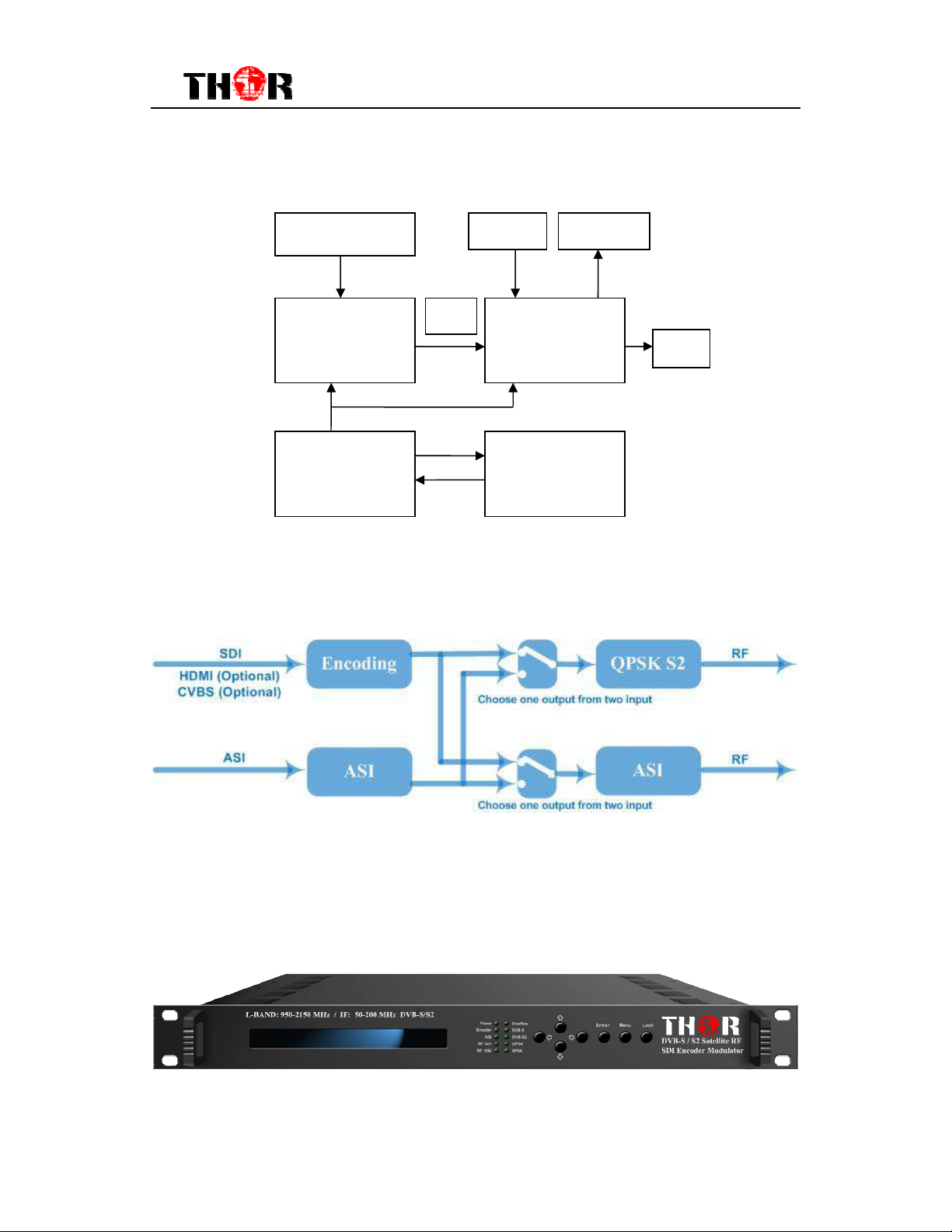
1.4 Principle Chart
THOR H-1SDI-DVB-S2
SDI /CVBS…
Encoder card Modulator
CPU
1.5 Functionality
ASI IN ASI OUT
TS
RF
Network
Interface
1.6 Appearance and Description
Front Panel Illustration
1 2 3 4 5
~ 3 ~
1 LCD Display
2 Mini-LED’s in green and red
3 D-Pad controls for left, right, up, down
4 Enter, Menu, Lock buttons
5 Rack Mountable 1 RU eye-holes
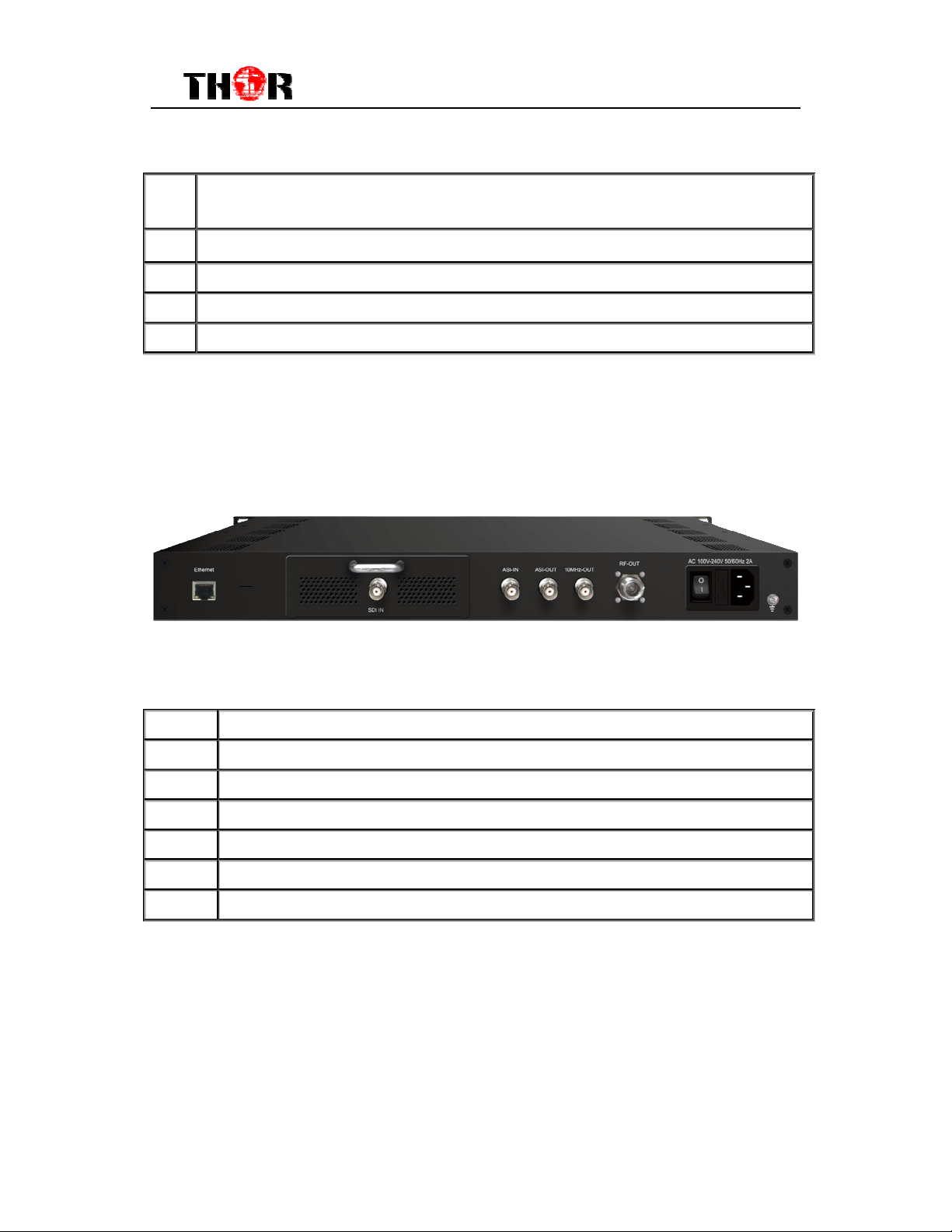
Rear Panel Illustration
THOR H-1SDI-DVB-S2
1 2 3 4 5 6 7
1 Ethernet RJ45 for Data and NMS Gui Interface
2 HD-SDI input (also HDMI, CVBS, SD-SDI available upon request)
3 ASI Input
4 ASI Output
5 10Mhz Output
6 RF Output
7 Power Switch and AC input
~ 4 ~
6
Chapter 2 Installation Guide
2.1 What’s in the Box
When you first receive your new DVB-S2 Encoder Modulator, please check to
make sure everything is included. If any pieces are missing please contact
Thor Fiber immediately.
H-HDSDI-DVBS2 HD Encoder Modulator
User’s Manual
SDI Cable
DC 12V Power Adapter
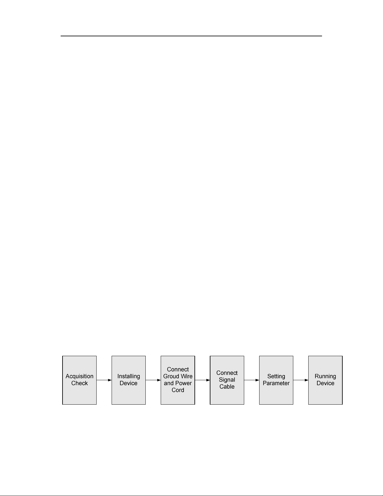
2.2 Installation Preparation
When you install the device, please follow the steps below:
Check the device for any damage during transportation
Prepare the environment for installation, easy access to rack
Connect Internet cable
Connect signal cables
2.2.1 Device’s Installation Flow Chart Illustrated as following::::

2.2.2 Environment Requirement
Item Requirement
When user installs machine on rack, the distance between
Machine Hall Space
2 rows of machine frames should be 1.2~1.5m and the
distance against wall should be no less than 0.8m.
Electric Isolation, Dust Free
THOR H-1SDI-DVB-S2
Machine Hall Floor
Environment
Temperature
Relative
Pressure
Door & Window
Wall
Fire Protection
Power
Humidity
Volume resistivity of ground anti-static material:
1X10⁷~1X10¹⁰Ω,Grounding current limiting resistance:
1MΩ (Floor bearing should be greater than 450Kg/㎡)
5~40℃(sustainable ),0~45℃(short time),
installing air-conditioning is recommended
20%~80% sustainable 10%~90% short time
86~105KPa
Make sure your installation area is free from any weather
hazards
Isolated Tech or Rack Room
Fire alarm system and extinguisher
Device power requires AC 110V±10%, 50/60Hz or AC
220V±10%, 50/60Hz. Please carefully check before
running.
2.3 Wire’s Connection
Connecting Power Cord
Insert one end into power supply socket, then insert the other end to DC
power.
Caution:
Before connecting power cord to H-HDSDI-DVBS2 HD Encoder &
Modulator, user should set the power switch to “OFF”.
~ 6 ~

THOR H-1SDI-DVB-S2
2.4 Signal Cables
Please have these extra necessities available during installation.
2.4.1 ASI cable illustration:
2.4.2 Network cable illustration:
2.4.3 SDI cable illustration:
~ 7 ~

THOR H-1SDI-DVB-S2
Chapter 3 Operation
The front panel of the H-1SDI-DVBS2 has an easy interface for manual
operation of the unit. For easier and more manageable access please connect
an RJ45 ethernet cable to the data port in the back to allow for the unit to be
accessed by IP using the built in NMS GUI.
Keyboard Function Description:
MENU:
previous menu.
ENTER:
change after modification.
LEFT/RIGHT:
UP/DOWN:
is inactivated.
LOCK:
the system will question the you to save present setting or not. If not, the LCD
will display the current configuration state.
Cancel current entered value, resume previous setting; Return to
Activate the parameters which need modification, or confirm the
Choose and set the parameters.
Modify activated parameter or paging up/down when parameter
Locking the screen / canceling the lock state. After pressing lock key,
3.1 Main Interface
Switch on the encoder modulator, the LCD will display the start state and the
main menu as below:
Start up………………………….
~ 8 ~

THOR H-1SDI-DVB-S2
►
3.2 General Setting
1 Alarm Status
2 Encode Setting
3 Modulate Setting
4 BISS Modulate
5 Network Setting
6 Saving Config
7 Loading Config
8 Version
From here you can establish all necessary configurations and modifications to
adjust the unit work properly in your infrastructure.
3.2.1 Alarm Status
Setting the triangle to point at menu 1, enter into this menu by pressing “Enter”.
If the device is working normally, it indicates No Warning as below:
Alarm Status
No Warning
The alarm indicator will turn on if there is no A/V signals input; or if there is a
TS bit rate overflows.
Alarm Status
TS overflow
3.2.2 Encode Settings
Similarly, enter this menu to modify parameters of video bit rate and audio bit
rate.
►
Video Bit Rate
Audio Bit Rate
Enter sub-menu Video Bit Rate to adjust the bit rate by pressing right/left and
up/down key and to confirm by pressing Lock key:
Video Bit Rate
08.000Mbps
~ 9 ~

THOR H-1SDI-DVB-S2
Audio Bit Rate can be selected similarly (bit rate range: 64 /96 /128 /192 /256
/320 Kbps):
Audio Bit Rate
►128 Kbps
3.2.3 Modulate Setting
Enter this menu (3) to set the parameters of modulation:
►
3.1 Modulate Mode
3.2 DVB-S FEC
3.3 DVB-S2 FEC
3.4 Symbol Rate
3.5 Roll Off
3.6 DVB-S2 Pilot
3.7 RF Frequency
3.8 RF Out Level
3.9 RF Out
3.10 Spec Invert
Modulate Mode: Select one of the following 3 modes: DVB-S, DVB-S2-QPSK
and DVB-S2-8PSK through UP/DOWN key and confirm the setting by pressing
Enter.
Modulate Mode
3.1.1 DVB-S
DVB-S FEC:
S
elect one DVB-S FEC from 1/2, 2/3, 3/4, 5/6 and 7/8 by
pressing RIGHT/LEFT key.
NOTE: Modulate Mode 3.1.1 DVB-S must be selected under menu 3.1,
then it will operational.
DVB-S FEC
1/2 2/3 3/4
DVB-S FEC:
S
elect one DVB-S2 FEC from QPSK1/2, QPSK3/5…and
~ 10 ~

THOR H-1SDI-DVB-S2
QPSK9/10 by pressing RIGHT/LEFT key.
NOTE: Modulate Mode 3.1.2 DVB-S2-QPSK or 3.1.3 DVB-S2-8PSK
must be selected under menu 3.1
DVB-S2 FEC
QPSK1/2 QPSK3/5
Symbol Rate: enter menu 3.4 to modify symbol rate (adjustable range:
0.050~20.000Mbps) by pressing right/left and up/down key and to confirm by
pressing Lock key
Symbol Rate
17.500 Mbps
Roll Off: enter menu 3.5 to select roll-off shown as below by pressing right/left
key and to confirm by pressing Lock key. Different Roll Off has different effects
on the max input bit rate.
Roll OFF
0.35 0.25 0.2
DVB-S2 Pilot: The DVB-S2 Pilot can be switched on or off through this
menu.
NOTE: Modulate Mode 3.1.2 DVB-S2-QPSK or 3.1.3 DVB-S2-8PSK
must be selected under menu 3.1, then it can be workable.
DVB-S2 Pilot
On Off
RF Frequency: The RF output frequency range is from 950 to 2150MHz with
1K stepping. After entering the RF frequency setting submenu, users the can
press LEFT, RIGHT, UP, and DOWN buttons to adjust the frequency and
confirm by pressing ENTER button. Remember to press LOCK and Save
~ 11 ~

THOR H-1SDI-DVB-S2
RF frequency
2000.000 MHz
RF out level: The RF attenuation range is from -16db-0, maximum output
level≥-8dbm with 0.1db step. After entering this setting submenu, user can
shift UP/DOWN/LEFT/RIGHT key to set the output level and press ENTER to
confirm.
RF Out Level
-00.0db
RF out: The RF out-mode can be selected under this menu: The modes
contain: single tone, modulation, test lation, and off lation.
RF Out
Single tone
Spec Invert: Switch to the Spec Invert mode between Normal and Invert
under this menu.
Spec Invert
Normal Invert
3.2.4 BISS Modulate
User can press “Enter” key to enter into below menu of t BISS Modulate.
4.1 BISS Mode Set
4.2 Program Select
4.3 SW Data
4.4 Select ID
4.5 ESW Data
4.6 Input Data
BISS Mode Set: Choose between Mode 1 and Mode E. Detailed operation will
~ 12 ~

THOR H-1SDI-DVB-S2
be explained in Chapter NMS Setting.
Program Select: Under this menu, users can modify the PID.
Program Select
PID: 0 x 0000
SW Data: When Mode 1 is selected, under this menu, users can input 12
characters from 0, 1, 2, 3, 4, 5, 6, 7, 8, 9, A, B, C, D, E, and F. More details
please refer to Chapter NMS Setting.
SW Data ID
123456EBEFEE
Select ID: Under Mode E, select Burned Key option or not. For more details
please refer to Chapter NMS Setting.
BISS Select ID
Inject ID Buried ID
ESW Data & Input ID: Under Mode E, the BISS scrambler completes
scrambling through ESW value and Input ID. Input the data and ID through the
LCD buttons panel.
ESW Data
1111111111222222
Input ID
11111111112222
3.2.5 Network Setting
Press “Enter” key to enter into below menu of the network settings and modify
the parameters under its corresponding submenus in the same way as was
shown above.
► 5.1 IP Address
5.2 Subnet Mask
5.3 Gateway
~ 13 ~

7.1 Load Saved CFG
THOR H-1SDI-DVB-S2
3.2.6 Saving Configuration
Choose to save the current configured parameters by pressing ENTER key.
The system displays the following message:
Saving, please wait:
Erasing…….
3.2.7 Loading Configuration
Restore the device into the last saved configuration by choosing the menu
7.1”Saved Config”, and also you can restore the device into factory default
configurations by choosing the menu 7.2”Default Config”.
7.2 Default CFG
Loading, please wait:
>>>>>>>>>>>>>>>>
3.2.8 Version
Check the device’s hardware version and software version at this submenu:
Soft 1.02 Hard 0.1
Build Apr 2012 Thor Fiber
~ 14 ~

THOR H-1SDI-DVB-S2
Chapter 4 NMS Settings
H-HDSDI-DVBS2 Encoder Modulator adopts web-based user interface, NMS
GUI. Before operating, you should ensure that the computer’s IP address is
different from the DVB-S2’s IP address; otherwise, it would cause an IP
conflict.
4.1 Login
The default IP of this device is 192.168.0.136. We can change the IP from the
front panel of the device. Then connect the pc to the device with RJ45 Cable,
and use ping command to confirm these two are in same Network or not. If the
PC IP address is 192.168.99.252, we change the Device IP to 192.168.99.196,
then we need to use the Web browser to connect the device with our PC.
Put the IP address of the unit in the any internet browser and press Enter.
You should input the user name and password (The default Username and
Password is ‘admin’ and ‘admin’ respectively) then click on ‘Login’ to enter the
welcome interface which is shown as follows:
~ 15 ~

THOR H-1SDI-DVB-S2
4.2 Parameter Configuration
4.2.1 Encoder:
Click on ‘Encoder’, it displays the program’s input information as below:
~ 16 ~

THOR H-1SDI-DVB-S2
4.2.2 BISS:
The BISS scrambling function application needs to be matched with a BISS
descrambler.
The BISS scrambling supports two modes: “Mode 1” and “Mode E”. Select one
of the two modes in the drop down list.
4.2.2.1 Mode 1
Under Mode 1, the BISS scrambler applies scrambling by a fixed Control Word
(CW), derived from a clear SW (Session Word). In Mode 1, a fixed 12-character
SW is inserted in the scrambler. The 64-bit CW is derived from the SW
according to DVB-CSA specification
Select Mode 1 in the drop-down menu, and then input the scrambler key. The
scrambler key consists of 12 characters from 0, 1, 2, 3, 4, 5, 6, 7, 8, 9, A, B, C, D,
E, and F. The downside device descrambler key equals SW Data on the BISS
.
scrambler side.
After inputting the scrambler key, press “Apply” to initial scrambling. A few
~ 17 ~

THOR H-1SDI-DVB-S2
seconds later, the programs will be scrambled.
4.2.2.2 Mode E
Under Mode E, the BISS scrambler completes scrambling through ESW Data
and Input ID. The ESW data equals Descrambler key on the downside device
side, while the input ID equals Burned Key on IRD side.
The select ID has two options: Device and
Input. If you choose Device, the Burned Key needs to be selected when
descrambling, while you choose Input and set Input data, on the downside
device side, users do not need to select Burned Key and input the Input data as
SK.
Under Mode E, select Burned Key option. The device will calculate new data
which works as a descrambling key. The new data is created by Descrambling
Key (refers ESW on scrambler side) and Burned Key (Input or Device mode on
the scrambler side). If you select Burned Key, it corresponds to the Device mode
selected on scrambler side; while if Burned Key unselected, it corresponds to
Input mode on scrambler side. The Input data is SK on the IRD. Input the SK in
the column as showed:
Mode E (Burned Key option unselected)
After selecting Mode E and Burned Key unselected, Input the 16 figure
Descrambler Key and 14 characters SK (the SK data refers to the Input Data on
scrambler side). Users should choose the characters from 0, 1, 2, 3, 4, 5, 6, 7, 8,
9, A, B, C, D, E, and F. Lastly users press “Set” to initial descrambling. A few
seconds later, the programs will be descrambled.
Note: Under this mode, after inputting the Descrambler Key and SK, it will work
out new data, which can be seen as the SW in Mode 1. The new data resulted
from Descrambler Key and SK implements descrambling function.
~ 18 ~

THOR H-1SDI-DVB-S2
Mode E (Burned Key option selected)
After selecting Mode E and Burned Key, Input the 16 figure Descrambler Key
(named ESW on scrambler side). Choose characters from 0, 1, 2, 3, 4, 5, 6, 7, 8,
and 9, A, B, C, D, E, and F. Under this mode, SK cannot be input in the column,
as the data which works with ESW has been embedded inside the device after
users select Burned Key (which refers that users choose Device mode on the
scrambler side). Lastly press “Set” to initial descrambling. A few seconds later,
the programs will be descrambled.
Note: The Burned Key is embedded in the device and it is solely controlled by
the device supplier.
Click Parse Prg to view the input programs and modify the program names as
their requirement. If you need to scramble the programs, mark the corresponding
boxes in front of the programs with √and click Set to activate the setting.
4.2.3 Modulator
Click Modulator on the left column and enter into the Modulate interface. For
more details please refer to 3.2.3 in this manual.
~ 19 ~

THOR H-1SDI-DVB-S2
Modulation mode
DVB-S FEC
DVB-S2 FEC
Symbol rate
Roll off
DVB-S2 pilot
RF frequency
RF out level
DVB-S
DVB-S2
QPSK
DVB-S2
8PSK
1/2, 2/3, 3/4,
5/6, 7/8
1/2, 3/5, 2/3,
3/4, 5/6, 8/9,
9/10;
the output range of symbol rate is 0.050-20.000Msps
0.25/0.3/0.35 selecting
DVB-S2 pilot ON/OFF selecting
RF frequency is ranged from 950.00-2150.00MHz
output level ranges from -16db-0, maximum output
level≥-8dbm with 0.1db step
it supports DVB-S, DVB-S2 QPSK and
DVB-S2 8PSK three modes
under DVB-S mode, it supports FEC 1/2, 2/3,
3/4, 5/6, 7/8
under DVB-S2 QPSK mode, it supports FEC
1/2, 3/5, 2/3, 3/4, 5/6, 8/9, 9/10;
Under DVB-S2 8PSK mode, it supports FEC
3/5, 2/3, 3/4, 5/6, 8/9, 9/10
RF out
RF 10MCLK Enable
Spec Invert
The modes contain: single tone, modulation, test lation, and off
lation.
RF 10MCLK ON/OFF selecting
User can switch the Spec Invert mode between Normal and
Invert under this menu.
~ 20 ~

4.2.4 Save/Restore
THOR H-1SDI-DVB-S2
When you click on ‘Save/Restore’ from the menu, it will display the screen as
shown below. Here we can save the configuration permanently to the device.
Click on ‘Save Configuration’, to store the data permanently to the device.
By using ‘Restore Configuration’ we can restore the latest saving configuration to
the device.
By using ‘Factory Set,’ user can set the default factory setting.
4.2.5 Reboot
When you click on ‘Reboot’ from the menu the screen will display as shown
below. Here, when we click on ‘Reboot’ box it will restart the device
automatically.
~ 21 ~

THOR H-1SDI-DVB-S2
4.2.6 Firmware
When you click on ‘Firmware’ from the menu, it will display the screen as shown
below. Here we can update the device by using the update file.
Click on ‘Browse’ to find the path of the devices update file for this device then
click on ‘Update’ to update the device.
After updating the device we need to restart the device by using the Reboot
option.
4.2.7 Network
When you click on ‘Network’, it will display the screen as shown below. It
displays the network information of the Device. Here we can change the devices
network configurations as needed.
~ 22 ~

4.2.8 Password:
THOR H-1SDI-DVB-S2
Change the password in this interface by putting the current username and
password, then inserting a new username and password.
After adding the new parrameters, click on ‘Apply’ to save the configuration.
4.2.9 Backup/Load
Click on ‘Backup/Load’ from the menu, it will display the screen as below.
~ 23 ~

THOR H-1SDI-DVB-S2
Backup Configuration – Here we can back up the device configuration file to a
folder by clicking on ‘Backup Config’.
Load Configuration – If we need to load a previously saved configuration to the
device then we can click on ‘Browse’ and find the backup configuration file
path. After selecting the file, click on ‘Load File’ to load the backup file to the
device.
~ 24 ~

THOR H-1SDI-DVB-S2
Chapter 5 Troubleshooting
THOR’s ISO9001 quality assurance system has been approved by CQC
organization. To guarantee the products’ quality, reliability and stability all
THOR products have been passed testing and inspection before heading to
logistics. The testing and inspection scheme already covers all of the Optical,
Electronic and Mechanical criteria which have been published by THOR. To
prevent any potential hazard, please strictly follow the operation conditions.
Prevention Measure
Installing the device at the place in which environment temperature between
0 to 45 °C
Making sure good ventilation for the heat-sink on the rear panel and other
heat-sink bores if necessary
Checking the input AC within the power supply working range and the
connection is correct before switching on device
Checking the RF output level varies within tolerant range if it is necessary
Checking all signal cables have been properly connected
Frequently switching on/off device is prohibited; the interval between every
switching on/off must greater than 10 seconds.
Conditions needed to unplug power cord
Power cord or socket damaged.
Any liquid gets into device.
Anything that will cause a circuit short
Damp environment
Device suffered from physical damage
Longtime idle processes
After switching on and restoring to factory settings, device still cannot work
properly.
Maintenance needed
~ 25 ~
 Loading...