

FIBER
4-ADHD Encoder Modulator
Manual

4-ADHD
This user manual has been written to help people who have to use, integrate and to install the product.
Some chapters require some prerequisite knowledge in electronics and especially in broadcast technologies
and standards.
Disclaimer
No part of this document may be reproduced in any form without the written permission of Thor Broadcast.
The contents of this document are subject to revision without notice due to continued progress in
methodology, design and manufacturing. Thor shall have no liability for any error or damage of any kind
resulting from the use of this document.
Copy Warning
This document includes some confidential information. Its usage is limited to the owners of the product
that it is relevant to. It cannot be copied, modified, or translated in another language without prior written
authorization from Thor Broadcast.

4-ADHD
Directory
CHAPTER 1 INTRODUCTION ........................................................................................................................... 1
1.1 PRODUCT OVERVIEW .................................................................................................................................... 1
1.2 KEY FEATURES .............................................................................................................................................. 1
1.3 SPECIFICATIONS ............................................................................................................................................ 2
1.4 PRINCIPLE CHART ......................................................................................................................................... 2
1.5 APPEARANCE AND DESCRIPTION ................................................................................................................... 3
CHAPTER 2 INSTALLATION GUIDE .................................................................................................................. 4
2.1 GENERAL PRECAUTIONS ............................................................................................................................... 4
2.2 POWER PRECAUTIONS ................................................................................................................................... 4
2.3 DEVICE’S INSTALLATION FLOW CHART ILLUSTRATED AS FOLLOWING .......................................................... 5
2.4 ENVIRONMENT REQUIREMENT ..................................................................................................................... 5
2.5 GROUNDING REQUIREMENT ......................................................................................................................... 6
CHAPTER 3 OPERATION ................................................................................................................................. 7
3.1 3.1 LCD MENU STRUCTURE ......................................................................................................................... 7
3.1 INITIAL STATUS ............................................................................................................................................. 9
3.2 GENERAL SETTING FOR MAIN MENU ............................................................................................................ 9
CHAPTER 4 WEB NMS OPERATION............................................................................................................... 16
4.1 LOGIN ......................................................................................................................................................... 16
4.2 OPERATION ................................................................................................................................................. 17
CHAPTER 5 TROUBLESHOOTING .................................................................................................................. 27
CHAPTER 6 PACKING LIST ............................................................................................................................. 28
CHAPTER 7 APPLICATION ............................................................................................................................. 29
7.1 APPLICATION EXAMPLE ............................................................................................................................... 29
APPENDIX ................................................................................................................................................ 31

4-ADHD
Chapter 1 Introduction
1.1 Product Overview
The Thor 4-ADHD series encoder is an all-in-one device that integrates encoding (MPEG-2,
MPEG-4/AVC H.264), modulation, and convert HDMI/YPbPr to a digital RF output sigal.
To meet various requirements, the 4-ADHD is also equipped with 1 ASI input, and output with 2
ASI ports and 1 IP port.
The signal source could vary from satellite receivers, closed-circuit television cameras, Blu-ray
players, and antenna (off air). Its output signals are to be received by TVs, STB, etc with the
correlated standard the unit is set to encode with (ATSC, DVB-T, DVB-C).
The 4-ADHD units are widely used in public places such as the mall, market hall, theatre, hotels,
restaurants and etc for advertising, monitoring, training and educating in company, schools,
campuses, and healthcare.
1.2 Key features
MPEG2 HD & MPEG4 AVC H.264 HD video encoding
DD AC3 (2.0), MPEG4-AAC, MPEG2-AAC, MPEG1 Layer II audio encoding
DD AC3 (2.0/5.1/7.1) passthrough
4* HDMI/YPbPr inputs
1*ASI in for re-mux; 1*RF in for RF mix
4* DVB-C RF out optional; ASI out; IP out
CC (Closed Caption) EIA608, (from CVBS source only)
Low Latency
LCN (Logical Channel Number) support
Excellent modulation quality 1080i(Mpeg-2) 1080p(H.264)
LCD display, Remote control and firmware
Web-based NMS management; Updates via web
1

4-ADHD
Encoding Section
Video (HDMI)
Encoding
MPEG2; MPEG4 AVC/H.264
Interface
HDMI*4
Resolution
1920*1080_60i, 1920*1080_50i,
1280*720_60p, 1280*720_50P
Low Delay
Normal, Mode 1, Mode 2
Aspect Ratio
4:3; 16:9
Audio (HDMI)
Encoding
MPEG1 Layer II; MPEG2-AAC; MPEG4-AAC;
DD AC3(2.0);
DD AC3 (2.0/5.1/7.1) passthrough
Interface
HDMI*4 (SPDIF Not Applicable)
Sample rate
48KHz
Bit rate
64/96/128/ 192/256/320kbps
Video (YPbPr)
Encoding
MPEG2; MPEG4 AVC/H.264
Interface
YPbPr*4 (RCA)
Resolution
1920*1080_60i, 1920*1080_50i;
1280*720_60p, 1280*720_50P
Audio (L/R)
Encoding
MPEG1 Layer II; MPEG2-AAC; MPEG4-AAC;
DD AC3(2.0);
DD AC3 (2.0/5.1/7.1) passthrough
Interface
4*Stereo/8*mono
Sample rate
48KHz
Bit rate
64/96/128/ 192/256/320kbps
DVB-C Modulator Section (Option)
Standard
J.83A (DVB-C), J.83B, J.83C
MER
≥43dB
RF frequency
30~960MHz, 1KHz step
RF output level
-30~ -10dbm (77~97 dbµV), 0.1db step
Symbol rate
5.000~9.000Msps adjustable
RF Out
4*DVB-C adjacent carriers combined output
J.83A
J.83B
J.83C
Constellation
16/32/64/128/
256 QAM
64/ 256 QAM
64/ 256 QAM
Bandwidth
8M
6M
6M
System
Local interface
LCD + control buttons
Remote management
Web NMS
Stream Out
2 ASI mirrored out (BNC type, 100M);
IP (4 SPTS) over UDP, RTP/RTSP out (RJ45,
100M)
NMS interface
RJ45, 100M
Language
English
General
Power supply
AC 100V~240V
Dimensions
482*400*44mm
Weight
4.5 kg
Operation temperature
0~45℃
M
U
X
ASI In
ASI Output
(Independent program packet output)
Carrier A
RF In
DVB-C
Modulating
DVB-C
Modulating
Carrier B
RF
MPEG-2/4 HD
Encoding 1
HDMI
Built-in
Combiner
YPbPr
CVBS video in for CC only
MPEG-2/4 HD
Encoding 2
HDMI
YPbPr
MPEG-2/4 HD
Encoding 3
HDMI
YPbPr
MPEG-2/4 HD
Encoding 4
HDMI
YPbPr
4 SPTS Output
CVBS video in for CC only
CVBS video in for CC only
CVBS video in for CC only
DVB-C
Modulating
DVB-C
Modulating
Carrier C
Carrier D
1.3 Specifications
1.4 Principle Chart
4-ADHD
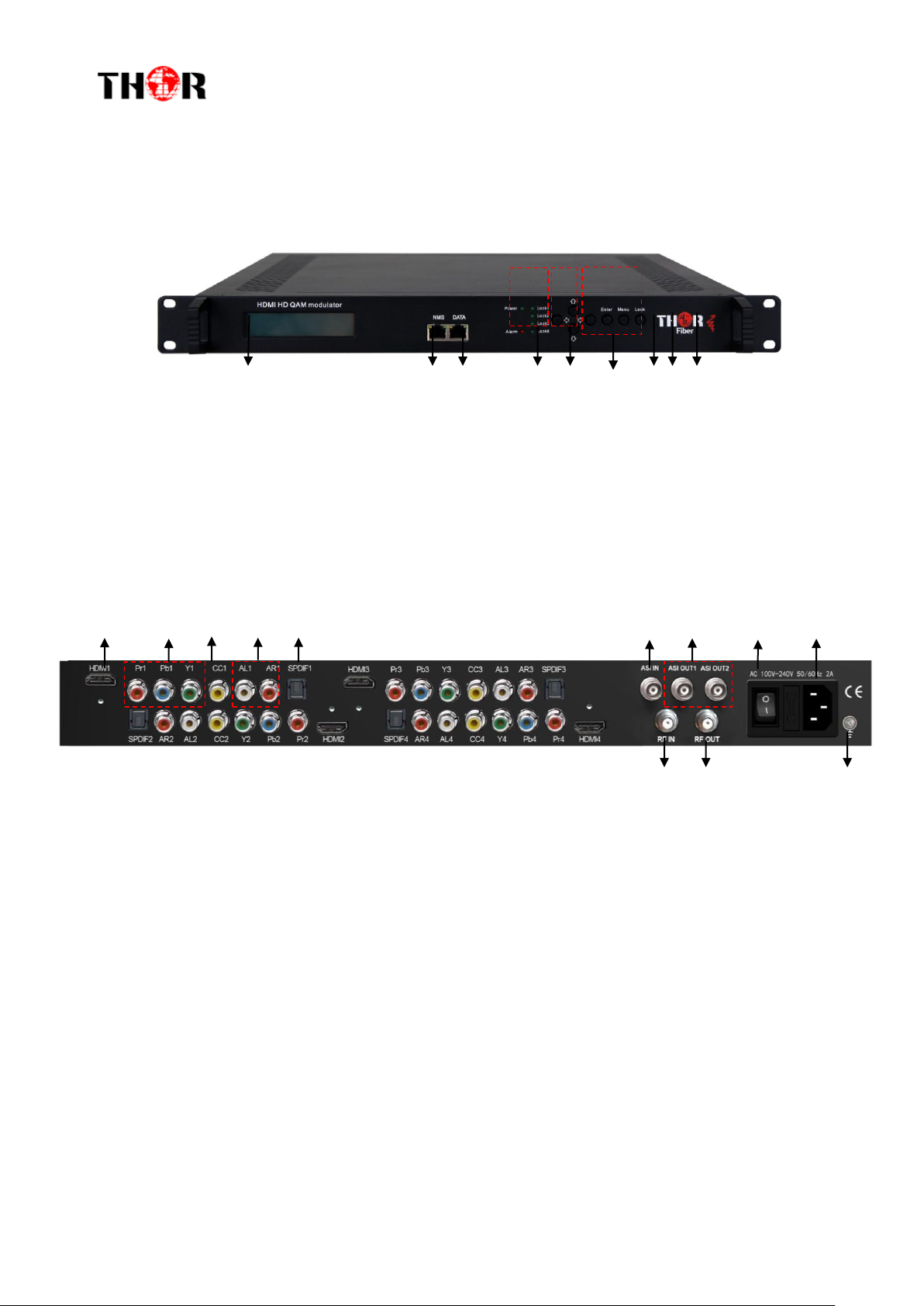
1.5 Appearance and Description
Front Panel Illustration
1 2 3 4 5 6 7 8 9
① LCD Screen
② NMS Port
③ Data Port
④ Power and Alarm Indicators
⑤ TS Lock Indicators
⑥ Up and Down, Left and Right Buttons
⑦ Enter Button: for confirm
⑧ Menu Button: for back step
⑨ Lock Button: press to lock set
Rear Panel Illustration
1 2 3 4 5 6 7 8 9
10 11 12
① HDMI input port
② YPbPr input port
③ CVBS input port for CC only
④ L/R Audio input (Stereo or Mono)
⑤ SPDF port(Not applicable at present)
⑥ ASI input port
⑦ ASI Output port 1&2
⑧ Power Switch
⑨ Power supply Slot
⑩ RF in port
⑪ RF out port
⑫ Grounding
3

4-ADHD
Chapter 2 Installation Guide
This section is to explain the cautions the users must know in some case that possible injure
may bring to users when it’s used or installed. For this reason, please read all details here and
make in mind before installing or using the product.
2.1 General Precautions
Must be operated and maintained in an area free of dust and debris.
The cover should be securely fastened, do not open the cover of the chassis when the power is on.
This will also void Thor’s manufacturer’s warranty.
After installation, securely stow away all loose cables, external antenna, and others.
2.2 Power precautions
Be careful when connecting a power source to the device.
Do not operate in wet or damp areas. Make sure the extension cable is in good
condition
Make sure the power switch is off before you start to install the device
4
4-ADHD
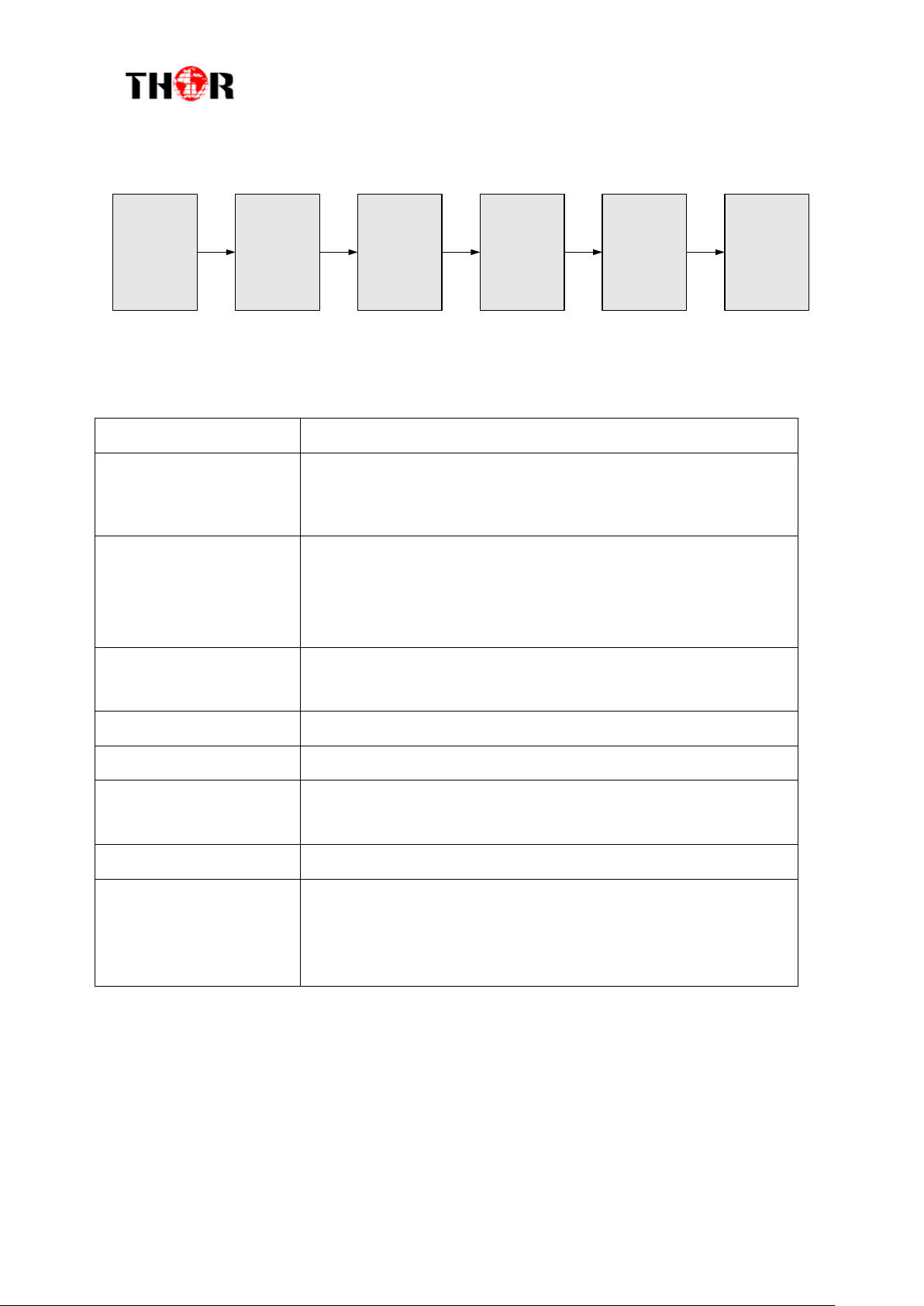
Connecting
Grouding
Wire and
Power
Cord
Acquisition
Check
Installing
Device
Setting
Parameter
Running
Device
Connecting
Signal
cable
Item
Requirement
Machine Hall Space
When installing unit on rack, the distance between 2 rows of
machine frames should be 1.2~1.5m and the distance against
wall should be no less than 0.8m.
Machine Hall Floor
Electric Isolation, Dust Free, HVAC
anti-static material: 1X10⁷~1X10¹⁰, Grounding current
limiting resistance: 1M (Floor bearing should be greater than
450Kg/㎡)
Environment
Temperature
5~40℃(sustainable ),0~45℃(short time),
installing air-conditioning is recommended
Relative Humidity
20%~80% sustainable 10%~90% short time
Pressure
86~105KPa
Door & Window
Installing rubber strip for sealing door-gaps and dual level
glasses for window
Fire Protection
Fire alarm system and extinguisher
Power
Device power, HVAC and lighting should be independent to
each other. Device power requires AC 110V±10%, 50/60Hz or
AC 220V±10%, 50/60Hz. Please carefully check before
running.
2.3 Device’s Installation Flow Chart Illustrated as following
2.4 Environment Requirement
5

4-ADHD
2.5 Grounding Requirement
It is important to keep this device grounded to ensure all of the modules function
correctly. Correctly grounding the device will also help prevent any electrical interference,
lightening. Etc. Also it helps reject minor interference that may disrupt the devices ability to
function smoothly. General rule of them, make sure the device is grounded when installing
anywhere.
Always use copper wire. When applied correctly the ground must be wrapped well to
ensure maximum conduction so it can reduce any high frequencies. The copper ground wire
should also be as short and thick as possible
Installer must make sure that the two ends of the ground are well conducted and have
appropriate anti-rust properties.
It is prohibited to use any other device as part of the grounding electric circuit.
The area of the conduction between the ground wire and device’s frame should be no
less than 25 ㎡.
6
4-ADHD
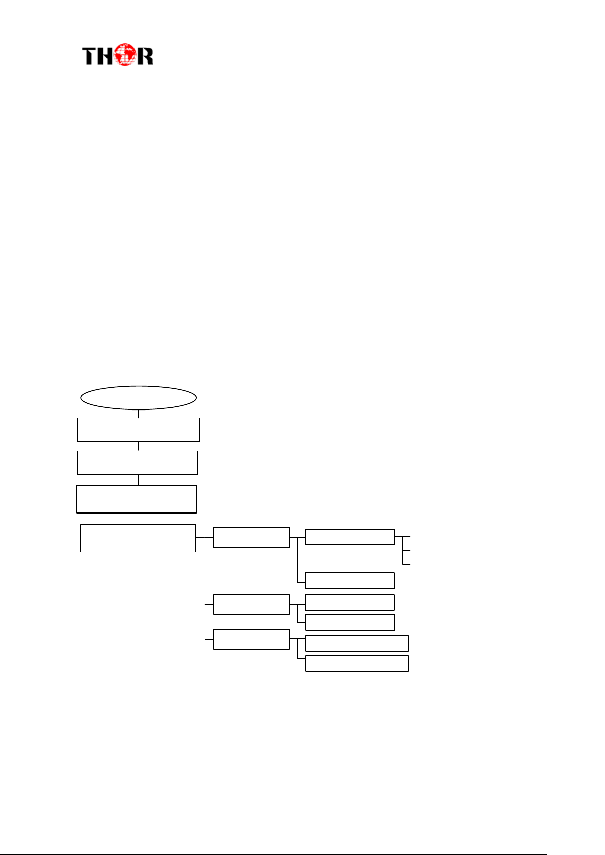
Switch On
Initializing
General Working
Status
1 Status
2 Input Sets
2.1 Input 1
2.3 Input 3
2.2 Input 2
Program Info
2.3.1 Parse Program
2.3.2 Mux Program
2.1.1 Program 1
2.1.2 Program 2
2.2.1 Program 1
2.2.2 Program 2
(Same content with 2.1.1)
(Same content with 2.1.1)
(Same content with 2.1.1)
Video
Audio
Chapter 3 Operation
Keyboard Function Description:
MENU: Cancel current entered value, resume previous setting; Return to previous menu.
ENTER: Activate the parameters which need modifications, or confirm the change after
modification.
LEFT/RIGHT: Choose and set the parameters.
UP/DOWN: Modify activated parameter or paging up/down when parameter is inactivated.
LOCK: Lock the screen/cancel the lock state. After pressing the lock key, the LCD will display the
current configuring state.
3.1 3.1 LCD Menu Structure
7
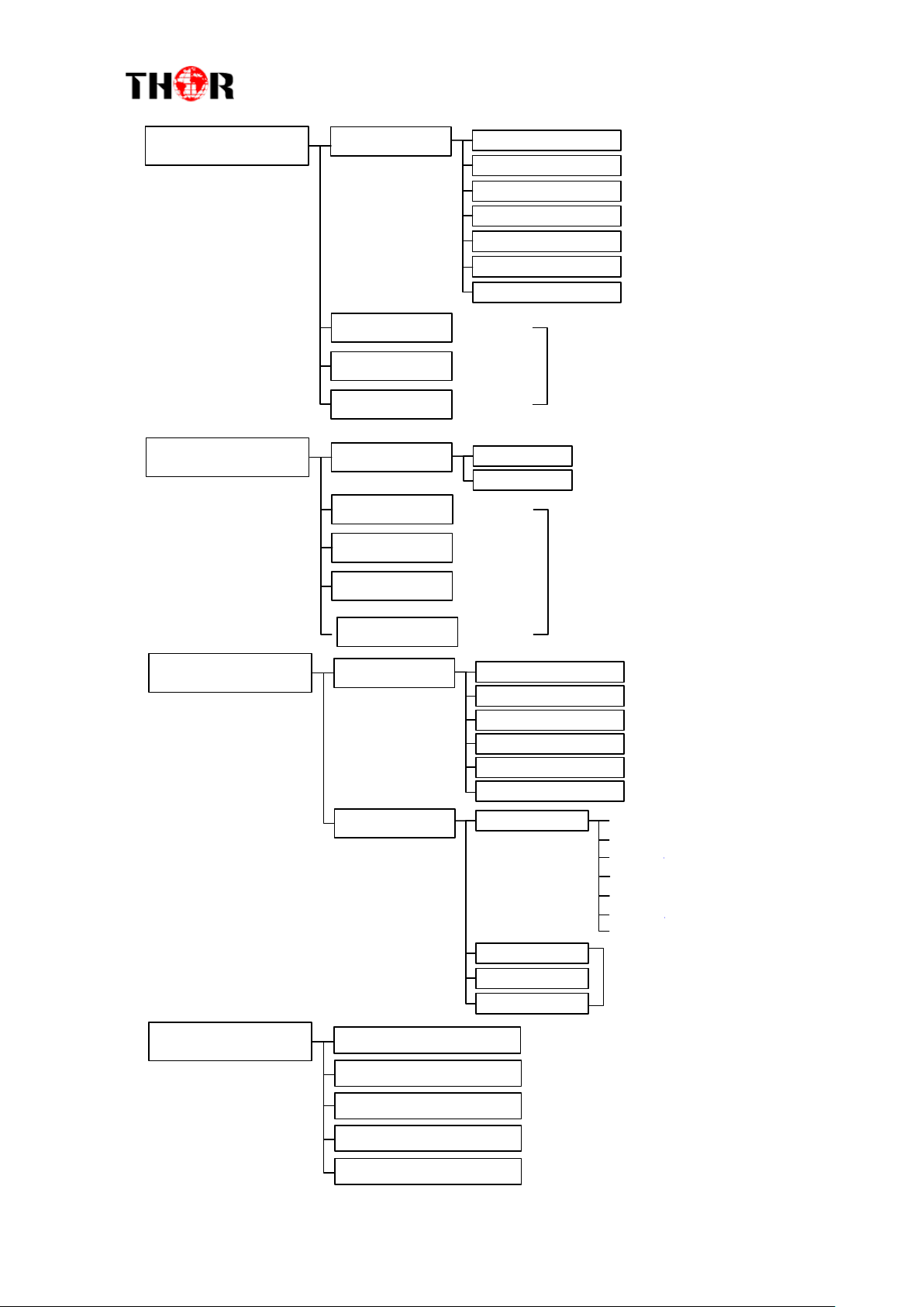
4-ADHD
3 Modulator
3.1 Output A
3.2 Output B
3.3 Output C
3.4 Output D
3.1.2 Standard
3.1.3 Constellation
3.1.4 Symbol Rate
3.1.5 RF Frequency
3.1.6 RF Out Level
3.1.1 RF On
3.2.1-3.2.7
(Same content with 3.1.1-3.1.7)
3.3.1-3.3.7
3.4.1-3.4.7
3.1.7 ASI output
4 TS Config
4.1 Output A
4.2 Output B
4.3 Output C
4.4 Output D
4.1.2 ON ID
4.1.1 TS ID
4.2.1-4.2.2
(Same content with 4.1.1-4.1.2)
4.3.1-4.3.2
4.4.1-4.4.2
4.5 Output E
4.5.1-4.5.2
5 Network
5.1 NMS
5.2 IP Stream
5.1.2 Subnet Mask
5.1.3 Gateway
5.1.4 MAC Address
5.1.5 Web NMS Port
5.1.6 Reset Password
5.1.1 NMS IP
5.2.2 IP Out 2
5.2.3 IP Out 3
5.2.4 IP Out 4
5.2.1 IP Out 1
Output IP
Data Enable
Null PKT Filter
Gateway
Output Port
Subnet Mask
Protocol
(Same content
with 5.2.1)
6 System
6.1 Save Config
6.2 Load Saved CFG
6.3 Factory Reset
6.4 LCD Time-out
6.6 Version
8
 Loading...