


CABLE
THG571 - Voice Over IP Cable Modem
User manual
SATELLITE
TELECOM
TERRES TRIAL
Important Information
This symbol means that your inoperative electronic appliance must be collected separately
and not mixed with the household waste. The European Union has implemented a specific
collection and recycling system for which producers' are responsible.
This appliance has been designed and manufactured with high quality
materials and components that can be recycled and reused. Electrical and electronic
appliances are liable to contain parts that are necessary in order for the system to work
properly but which can become a health and environmental hazard if they are not handled or
disposed of in the proper way. Consequently, please do not throw out your inoperative
appliance with the household waste.
If you are the owner of the appliance, you must deposit it at the appropriate local collection
point or leave it with the vendor when buying a new appliance.
- If you are a professional user, please follow your supplier's instructions.
- If the appliance is rented to you or left in your care, please contact your service
provider.
Help us protect the environment in which we live!
ii

Important Information
iii
North American Cable Installer This reminder is provided to call your attention to Article 820-40 of the
National Electrical Code (Section 54 of the Canadian Electrical Code, Part 1) which provides guidelines for
proper grounding and, in particular, specifies that the cable ground shall be connected to the grounding system
of the building as close to the point of cable entry as practical.
Power Supply Information
The power supply can be unplugged to turn off main power to the cable modem. It should also be easily
accessible in an emergency.
Power Cord Requirement
This product must be operated with the supplied line cord or with a line cord meeting IEC227 H03 VV-F or
IEC227 H03 VVH2-F having conductors with a cross-sectional area not less than .75mm2.
Operating Information
Operating Temperature: 0˚ to 40˚ C (32˚ to 104˚ F)
Storage Temperature: -20˚ to 70˚ C (-4˚ to 158˚ F)
If you purchased this product at a retail outlet, please read the following:
Product Registration
Please fill out the product registration card that came with this product and return it immediately.
Returning the card allows us to contact you if needed.
Keep your sales receipt to obtain warranty parts and service and for proof of purchase. Attach it here and
record the serial and model numbers in case you need them. The numbers are located on the back of the
product.
Model No. ____________________________ Serial No _____________________________
Purchase Date: _________________________ Dealer/Address/Phone: __________________

Table of Contents
Table of Contents
Table of ContentsTable of Contents
CHAPTER 1: CONNECTIONS AND SETUP ............................................................................................................. 1
INTRODUCTION ........................................................................................................................................................... 1
CABLE MODEM FEATURES ............................................................................................................................................................ 1
WHAT’S ON THE CD-ROM ............................................................................................................................................................ 2
ACCESSING THE DIAGNOSTICS DISPLAY THROUGH THE CD-ROM ............................................................................................. 2
COMPUTER REQUIREMENTS ......................................................................................................................................................... 2
CABLE MODEM OVERVIEW ..................................................................................................................................... 3
FRONT PANEL ................................................................................................................................................................................. 3
REAR PANEL................................................................................................................................................................................... 5
WALL MOUNTING .......................................................................................................................................................................... 6
RELATIONSHIP AMONG THE DEVICES ........................................................................................................................................... 7
WHAT THE MODEM DOES ............................................................................................................................................................. 7
WHAT THE MODEM NEEDS TO DO ITS JOB................................................................................................................................... 7
CONTACT YOUR LOCAL CABLE COMPANY ................................................................................................................................... 8
CONNECTING THE CABLE MODEM ....................................................................................................................... 9
CONNECTING THE CABLE MODEM TO A SINGLE COMPUTER ...................................................................................................... 9
ATTACHING THE CABLE TV WIRE TO THE CABLE MODEM ......................................................................................................... 9
IMPORTANT CONNECTION INFORMATION .................................................................................................................................. 10
ETHERNET CONNECTION TO ONE COMPUTER ........................................................................................................................... 10
CONNECTING MORE THAN ONE COMPUTER TO THE CABLE MODEM ....................................................................................... 11
TELEPHONE OR FAX CONNECTION ............................................................................................................................................. 12
ACTIVATING THE CABLE MODEM ............................................................................................................................................... 13
ACTIVATING THE EMTA .......................................................................................................................................... 13
ACCESSING THE INTERNET ................................................................................................................................... 13
BASIC STATUS WEB PAGE GROUP ........................................................................................................................ 14
BASIC LAN .................................................................................................................................................................................. 14
HARDWARE INFO ......................................................................................................................................................................... 15
EVENT LOG .................................................................................................................................................................................. 15
CM STATE .................................................................................................................................................................................... 16
INITIAL SCAN ............................................................................................................................................................................... 17
CHAPTER 2: ADDITIONAL INFORMATION ........................................................................................................ 18
iv

Table of Contents
Table of Contents
Table of ContentsTable of Contents
FREQUENTLY ASKED QUESTIONS ....................................................................................................................... 18
GENERAL TROUBLESHOOTING ........................................................................................................................... 19
FCC DECLARATION OF CONFORMITY AND INDUSTRY CANADA INFORMATION ................................ 20
SERVICE INFORMATION ......................................................................................................................................... 20
GLOSSARY ................................................................................................................................................................... 21
v

Chapter 1: Connection and Setup
Chapter 1: Connection and Setup
Chapter 1: Connection and SetupChapter 1: Connection and Setup
Chapter
Chapter 1: Connections and Setup
ChapterChapter
Introduction
Introduction
IntroductionIntroduction
Cable Modem Features
CableLabs DOCSIS 1.0/1.1/2.0/3.0 Standard Compliant. / Cable Europe Lab EuroDOCSIS
1.0/1.1/2.0/3.0 Standard Certified.
Support Multiple Provisioning Modes.
Support PacketCable / EuroPacketCable NCS 1.0/1.5/2.0 (optional) MGCP 1.0 compliant (Media
Gateway Control Protocol) (optional configuration: SIP).
Standard RJ-45 connector for 10/100/1000BaseT Ethernet with auto-negotiation and MDIX functions;
Support maximum Ethernet cable length up to 100m (Category 5).
Support up to 8 downstream channels and up to 4 upstream channels.
Giga tuner design.
Maximum data rate upstream up to 131Mbps (Theoretical) and downstream up to 440 Mbps
(Theoretical).
1: Connections and Setup
1: Connections and Setup1: Connections and Setup
Two RJ-11 Foreign Exchange Station (FXS) ports for IP telephony; Support a maximum line length
between themselves and an end-receiver (handset, answering phone, etc.) of up to 500 feet (AWG
26/0.4mm).
Support simultaneous voice and data communications.
Two simultaneous voice conversations in the different FXS ports with different CODEC: PCM A-law,
PCM µ-law, G.723.1, G.729, G.729a, G.729e, G.728, G.726, iLBC and BV16.
Echo Cancellation.
Voice Active Detection (VAD).
DTMF detection and generation.
Comfort Noise Generation (CNG).
Support V.90 fax and modem services.
Transparent bridging for IP traffic.
Remote operating firmware downloading.
Support Web pages and private DHCP server for status monitoring.
Clear LED display
Support 5 REN when DC offset disable
Both connections are not linked together (TEL1 is not connected to TEL2). Connection in general used
in Europe: Pin 3 and 4 are used on port Tel1, Pin3 and 4 are used on port Tel2.
Individual FXS ports, Tel1 and Tel2 phone jacks are not cross wired.
TEL 1 and TEL 2 port are not connected on Hardware side.
The following may affect the speed of your cable modem: your computer equipment and configuration
(processor speed, amount of RAM, available disk space); the number of programs you are running at the
same time; the capacity of your ISP; network traffic levels; the Ethernet device in use on your computer.
Your cable company may or may not fully support the speed capabilities of this modem.
1

Chapter 1: Connection and Setup
Chapter 1: Connection and Setup
Chapter 1: Connection and SetupChapter 1: Connection and Setup
What’s on the CD-ROM
Insert the cable modem CD-ROM into your CD-ROM drive to view troubleshooting tips, the internal
diagnostics, and other valuable information.
CD-ROM Contents:
• Electronic file of the instruction book in additional languages
• Usage and troubleshooting tips
Accessing the Diagnostics Display through the CD-ROM
A button on the CD-ROM menu called “Look at Diagnostics” (found under the “About My Cable
Modem” menu) launches your browser and displays status and diagnostic information stored within the
modem in HTML format (if allowed by the cable operator).
You may want to “bookmark” the IP address in your browser after the diagnostics page is displayed.
Computer Requirements
Personal computer with the following minimum system requirements (note that the minimum requirements
may vary by Cable Company):
CPU
System RAM
Operating System
Available Disk Space
Video
CD-ROM Drive
Ethernet
IBM PC COMPATIBLE MACINTOSH**
Pentium preferred PowerPC or higher
16MB (32MB preferred) 24MB (32MB preferred)
Windows* 2000/XP/VISTA Mac OS** 7.6.1 or higher
125MB 50MB
VGA or better (SVGA preferred) VGA or better (SVGA built-in preferred)
Required Required
10BaseT, 100BaseT,1000BaseT 10BaseT, 100BaseT,1000BaseT
An Ethernet card makes it possible for your computer to pass data to
and from the internet. You must have an Ethernet card and software
drivers installed in your computer. You will also need a standard
Ethernet cable to connect the Ethernet card to your cable modem.
*Windows is a trademark of the Microsoft Corporation.
**Macintosh and the Mac OS are trademarks of Apple Computer, Inc.
2
Chapter 1: Connections and Setup
From SYNC compl
eted, receiving UCD to
During DHCP, configuration file
Wait registration with all DS and all
From 1 to 4 DS, from 1 to 4 LEDs are
From 1 to 2 US, from 2 to 3 LEDS are
Wait registration with all DS and all
Registration
Cable Modem Overview
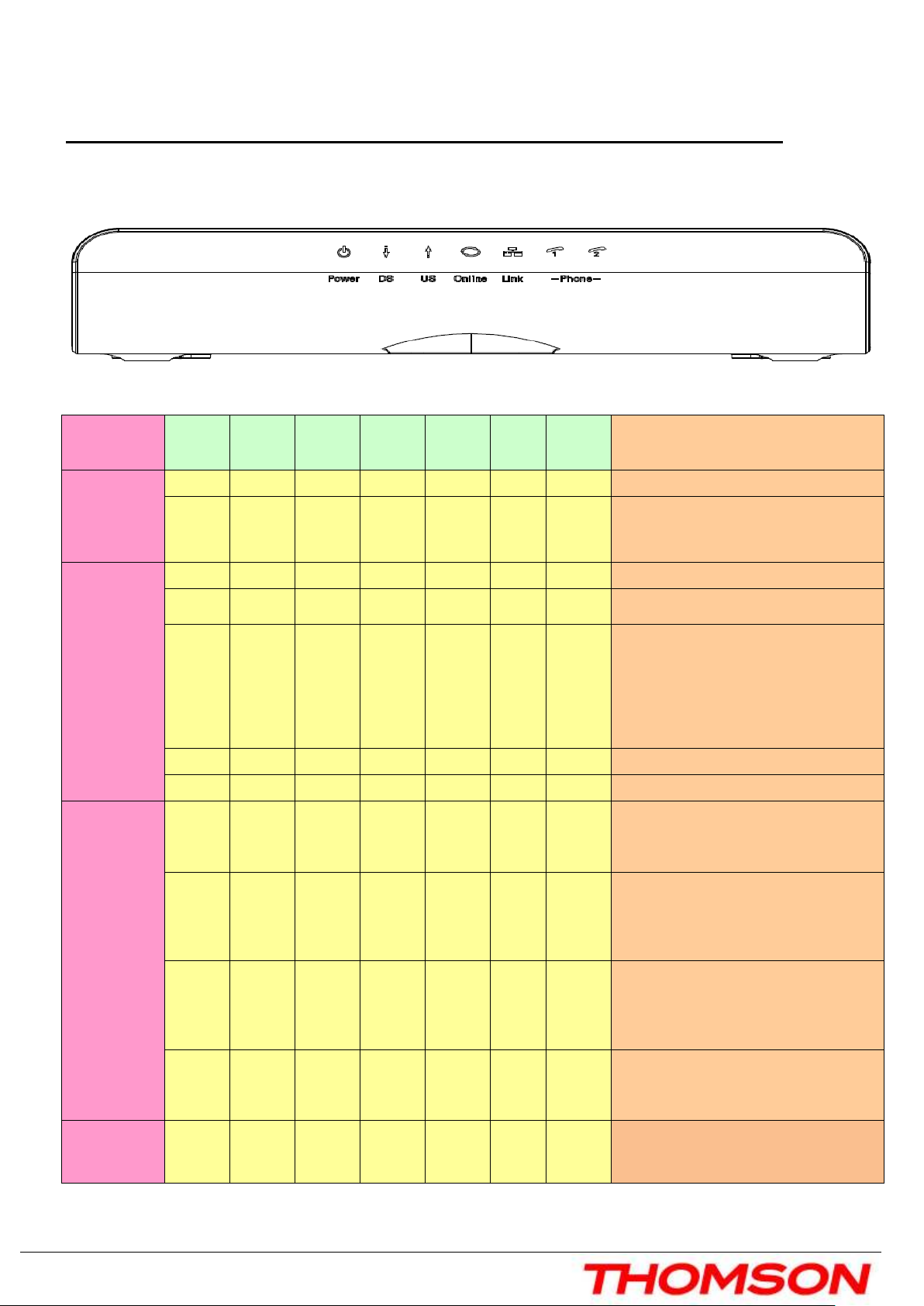
Front Panel
The following illustration shows the front panel of the model:
The LEDs on the front panel are described in the table below (from left to right):
THG57
THG571111 Power
THG57THG57
Boot-up
Operation
ON ON ON ON ON ON ON Power on 0.25 sec
ON FLASH FLASH FLASH
DS US ONLINE LINK TEL1 TEL2 Description
X X X
Following system initialization
complete to (before) DS scanning
DOCSIS
Start-up
Operation
Channel
Bonding
Operation
ON FLASH
ON ON FLASH
ON ON ON FLASH
ON ON ON ON X X X Operational (NACO=ON)
ON FLASH FLASH OFF X X X
FLASH FLASH FLASH FLASH FLASH
X X X X OFF X X
OFF X X OFF OFF X X
X X X X X During DS scanning and acquiring SYNC
X X X X
X X X
X X
ranging completed
download, registration, and Baseline
Privacy initialization
DHCP status, LED SHOULD be ON 1 sec,
and OFF 1 sec
TFTP status, LED SHOULD be ON 0.25
sec, and OFF 0.25 sec
US – Lights Flash sequentially from the
right to left
right to left
right to leftright to left
Minimum duration 3 seconds
ON.
From 5 to 8 DS, From 1 to 4 LEDs are
flashing
Duration 3 seconds
ON.
From 3 to 4 US, from 2 to 3 LEDS are
flashing.
Duration 3 seconds
FLASH FLASH FLASH FLASH FLASH
CM
ON ON ON ON X X X
3
X X
US – Lights Flash sequentially from the
left to right
left to right
left to rightleft to right
Minimum duration 3 seconds
No US/DS Channel Bonding and
Registered with Pre-D30 CMTS (Green
LEDs)

Chapter 1: Connections and Setup
Flavors
Installation 3
.0
Installation D3.0
the color of this LED will be Blue if
SW
ON ON ON ON X X X
ON ON ON ON X X X DS Channel Bonding (BLUE LEDs)
ON ON ON ON X X X US Channel Bonding (BLUE LEDs)
ON FLASH
ON ON X X X
US/DS Channel Bonding and Registered
with D30 mode (BLUE LEDs)
DS Partial service
US Channel bonding
ON ON FLASH
ON X X X
US Partial service
DS channel bonding
Installation D3.0
ON FLASH FLASH
ON X X X
DS & US Partial service
ON ON ON ON X X X
No US/DS Channel Bonding but
Registered with D30 mode
MTA
initialization
CPE
Operation
Download
Operation
ON ON ON ON X FLASH OFF MTA DHCP
ON ON ON ON X OFF FLASH MTA SNMP/TFTP
ON ON ON ON X FLASH FLASH RSIP for NCS/Register for SIP
ON X X X
ON FLASH FLASH
ON X X X
OFF
ON
FLASH
X X
OFF: No Ethernet carrier present
ON: Ethernet carrier present, not traffic
FLASH: Ethernet TX/RX traffic
Note:
Note:
Note:Note:
it's linked to Gigabit
A software download and while
updating the FLASH memory
4
 Loading...