

Page 1
TD5130
Setup & User Guide
Copyright © 2012 Technicolor. All rights reserved.
DMS-CTC-20120508-0000 v1.0.
Page 2

2
SETUP & USER GUIDE
Table of Contents
1 PRODUCT OVERVIEW ....................................................................................... 4
1.1 Features ................................................................................................... 4
1.2 Hardware Overview ..................................................................................... 5
1.2.1 Front Panel ............................................................................................ 5
1.2.2 Rear Panel ............................................................................................. 6
2 INSTALLATION ................................................................................................ 7
2.1 Connect the Power ..................................................................................... 7
2.2 Connect Wired Devices ................................................................................ 7
2.3 Connect Wireless Devices ............................................................................ 8
2.3.1 WLAN ................................................................................................... 8
2.3.2 Wi-Fi Protected Setup (WPS) ....................................................................... 8
2.4 Connect the Broadband (DSL) ....................................................................... 8
2.4.1 Use a Splitter .......................................................................................... 8
2.5 Check the Installation .................................................................................. 9
3 CONFIGURE THE COMPUTER ............................................................................ 10
3.1 Windows XP ............................................................................................. 10
3.2 Windows Vista .......................................................................................... 10
3.3 Windows 7 ............................................................................................... 11
4 ACCESS THE WIRELESS GATEWAY .................................................................... 12
4.1 Login ...................................................................................................... 12
4.2 The Interface ............................................................................................ 13
4.3 Using the Menu ......................................................................................... 14
4.4 Configuration Wizard ................................................................................. 14
5 TECHNICOLOR GATEWAY................................................................................. 20
5.1 System Information .................................................................................... 20
5.2 System Configuration ................................................................................. 21
5.2.1 DSL Service Configuration ........................................................................ 21
5.2.2 Date and Time Configuration...................................................................... 21
5.2.3 Web Browsing Interception ........................................................................ 22
5.3 Event Logs .............................................................................................. 22
6 BROADBAND CONNECTION .............................................................................. 23
6.1 DSL Connection ........................................................................................ 23
6.2 Internet Services ....................................................................................... 24
7 TOOLBOX ...................................................................................................... 25
7.1 Remote Assistance .................................................................................... 25
7.1.1 Enable Remote Assistance ........................................................................ 25
7.1.2 Disable Remote Assistance ....................................................................... 26
Copyright © 2012 Technicolor. All rights reserved.
DMS-CTC-20120508-0000 v1.0.
Page 3

3
SETUP & USER GUIDE
7.2 Game & Application Sharing ........................................................................ 26
7.2.1 Assign a Game or Application .................................................................... 27
7.2.2 Modify Assigned Game or Application ........................................................... 28
7.2.3 Create a New Game or Application .............................................................. 28
7.2.4 Modify a Game or Application ..................................................................... 29
7.3 Parental Control ........................................................................................ 30
7.4 Firewall ................................................................................................... 31
7.4.1 Change Firewall Security Level ................................................................... 31
7.4.2 Create a New Security Level ...................................................................... 31
7.4.3 Set Filter Rules ...................................................................................... 32
7.5 Intrusion Detection .................................................................................... 33
7.6 Dynamic DNS ........................................................................................... 33
7.7 User Management ...................................................................................... 34
7.7.1 Add New User ....................................................................................... 34
7.7.2 Reset Password ..................................................................................... 34
7.7.3 Manage Users ....................................................................................... 34
7.8 DMZ ....................................................................................................... 35
8 HOME NETWORK ............................................................................................ 36
8.1 Devices ................................................................................................... 36
8.1.1 View or Modify Device Information ............................................................... 36
8.1.2 Assign Game or Application to Device ........................................................... 37
8.1.3 Remove a Shared Game or Application ......................................................... 37
8.1.4 Assign a Public IP Address to Device ........................................................... 37
8.2 Interfaces ................................................................................................ 38
8.2.1 Local Network Interface ............................................................................ 38
8.2.2 Wireless Access Point ............................................................................. 39
APPENDIX A WIRELESS CONSIDERATIONS .............................................................. 43
APPENDIX B REGULATORY & SAFETY INFORMATION ................................................ 44
APPENDIX C SPECIFICATIONS .............................................................................. 46
Copyright © 2012 Technicolor. All rights reserved.
DMS-CTC-20120508-0000 v1.0.
Page 4

4
SETUP & USER GUIDE
1 Product Overview
Thank you for choosing Technicolor Wireless n ADSL2+ Gateway. This Wireless Gateway combines the
functionality of an ADSL / ADSL2 / ADSL2+ modem and Internet gateway in one. The var ious security
features, such as WPS, WPA2, SPI, and NAT, protect your data and privacy online . The web-based utility
allows you to configure your Wireless Gateway easily.
1.1 Features
▪ Compliant with ADSL G.dmt (G.992.1), G.lite (G.992.2) standards
▪ Compliant with ADSL2 G.dmt.bis (G.992.3) and ADSL2 + G.992.4 standards
▪ Up to Up to 24Mbps downstream, 1.2Mbp s u p stream with ADSL2+ service
▪ IEEE 802.11b/g/n infrastructure operating modes
▪ Supports IPv4 and IPv6 protocols
▪ Supports web-based configuration
▪ Supports Command Line Interface (CLI) via Telnet
▪ Supports NAT, SPI
▪ Supports VLAN and QoS
▪ Supports firewall protection
▪ Supports up to 8 permanent virtual circuits (PVC)
▪ Supports Wi-Fi Multimedia (WMM)
▪ Supports Wi-Fi Protected Setup (WPS) for easy connection
▪ Supports wireless data encryption with 64/128-bit WEP standard
▪ Supports enhance security for W PA-TKIP, WPA2-AES, WPA, and WPA2
Copyright © 2012 Technicolor. All rights reserved.
DMS-CTC-20120508-0000 v1.0.
Page 5
5
SETUP & USER GUIDE
1 2 3 4 5
6
1.2 Hardware Overview
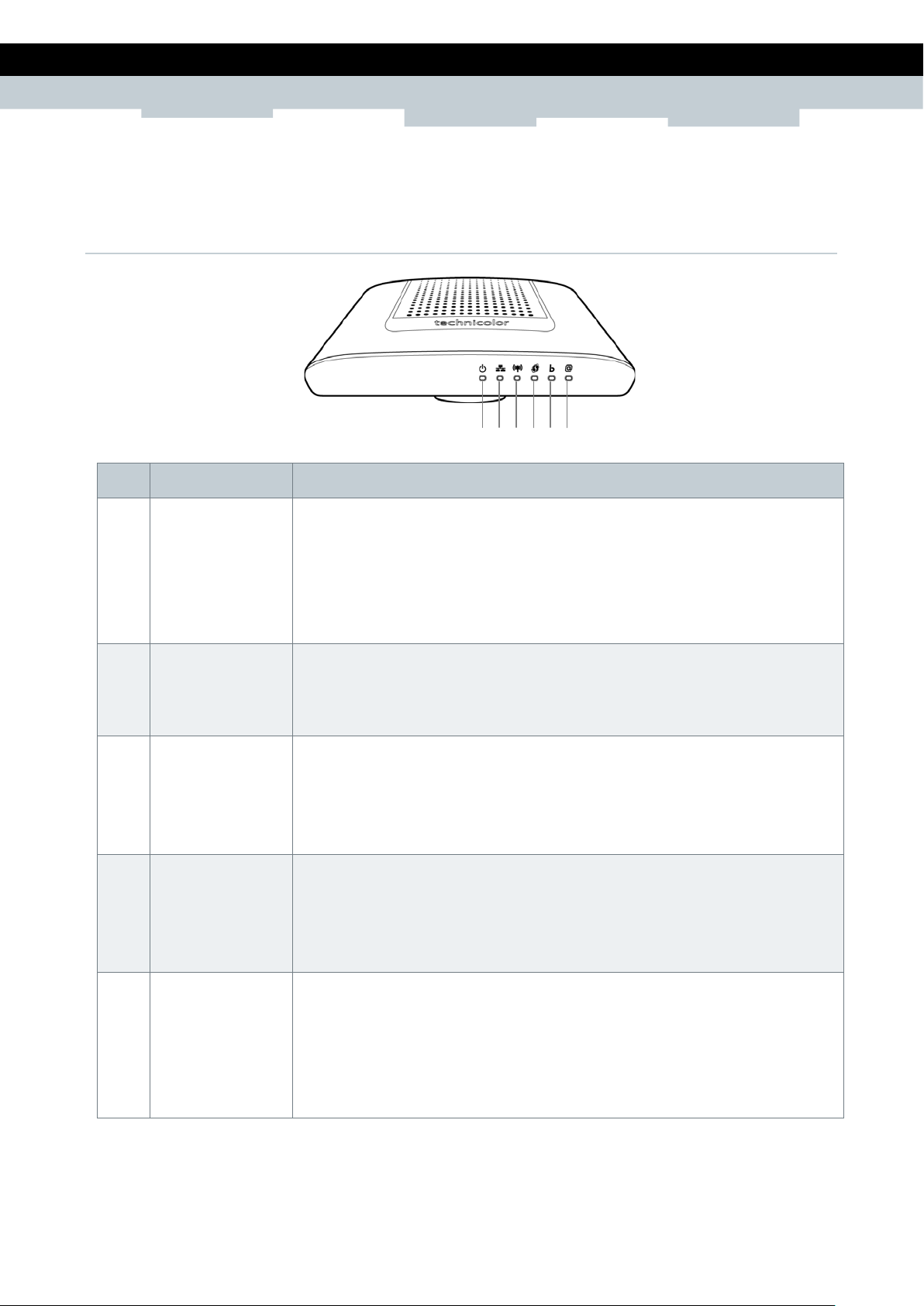
1.2.1 Front Panel
No. LED Description
1 Power LED Lights up when the device is powered on.
▪ Solid GREEN – Indicates normal operation.
▪ Flashing GREEN – Firmware upgr ad e in progress.
▪ Solid RED – Indicates malfunction.
▪ Off – The device is powered off.
2 Ethernet LED
3 WLAN LED Lights up to indicate wireless c onnection.
4 WPS LED Lights up to indicate the Wi-Fi Protected Setup (WPS) connection status.
▪ Solid GREEN – A wired connection is established.
▪ Flashing GREEN – Data transmission is in progress.
▪ Off – No wired connection detected.
▪ Solid GREEN – Wireless connection is established.
▪ Flashing GREEN – Data transmission is in progress.
▪ Off – Wireless connection is disabled.
▪ Solid GREEN – WPS is enabled.
▪ Flashing RED – Failure.
▪ Off – WPS is disabled.
5 Broadband (DSL)
LED
Copyright © 2012 Technicolor. All rights reserved.
DMS-CTC-20120508-0000 v1.0.
Lights up to indicate DSL connection status.
▪ Flashing GREEN (slow) – DSL lin e d e t e ction in progress.
▪ Flashing GREEN (fast) – Attempt s to synchronize with DSL line.
▪ Solid GREEN – DSL connection is established.
▪ Off – Modem power is off.
Page 6
6
SETUP & USER GUIDE
1
2
3 4 5
6 7 8
No. LED Description
6 Internet LED Lights up to indicate Internet connection status.
▪ Solid GREEN – Internet is connected but no activity.
▪ Flashing GREEN – Data transmission is in progress.
▪ Solid RED – Internet connection failed.
▪ Off – No internet connection.
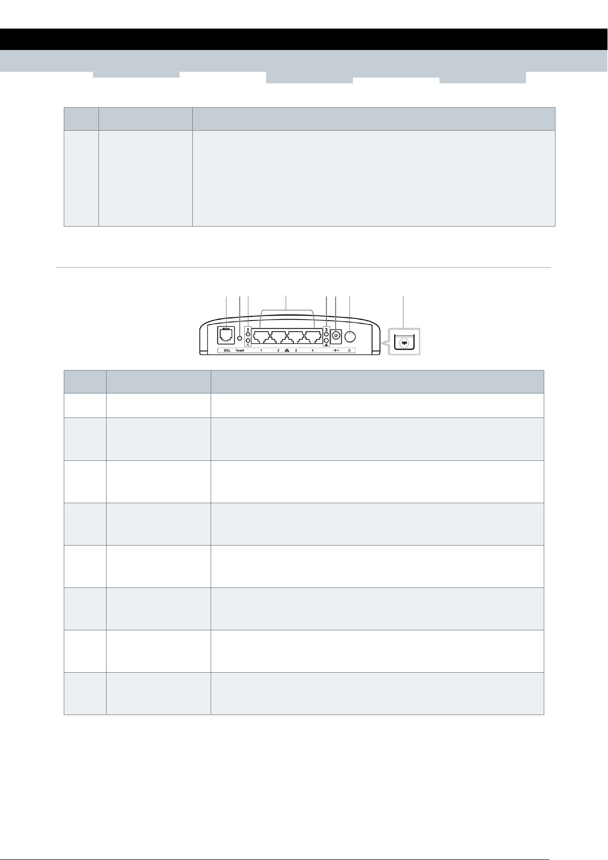
1.2.2 Rear Panel
No. Ports / Buttons Description
1 DSL port Connects to the DSL line using the RJ-11 cable.
2 Reset button Press and hold this button for at least 10 seconds to restore your
device to its original factory default setting.
3 LAN LED 1, 2 The LAN LED (1, 2) lights up when a device is connected to the
Ethernet port (1, 2).
4 Ethernet port
1, 2, 3, 4
5 LAN LED 3, 4 The LAN LED (3, 4) lights up when a device is connected to the
6 DC In jack Connects to the power adapter.
7 Power button Press to turn your device on or of f.
Connects a computer and other Ethernet network devices to the
Wireless Gateway using RJ-45 cables.
Ethernet port (3, 4).
8 WPS button Press 1 to 8 seconds to enable or disable WLAN.
Copyright © 2012 Technicolor. All rights reserved.
DMS-CTC-20120508-0000 v1.0.
Press for more than 8 seconds t o e nable WPS.
Page 7
7
SETUP & USER GUIDE
▪
▪
Connect all devices to your Wireless Gateway before connecting the power adapter to a wall
When setting up the Wireless Gateway for the first time, connect the host computer via Ethern
connection.
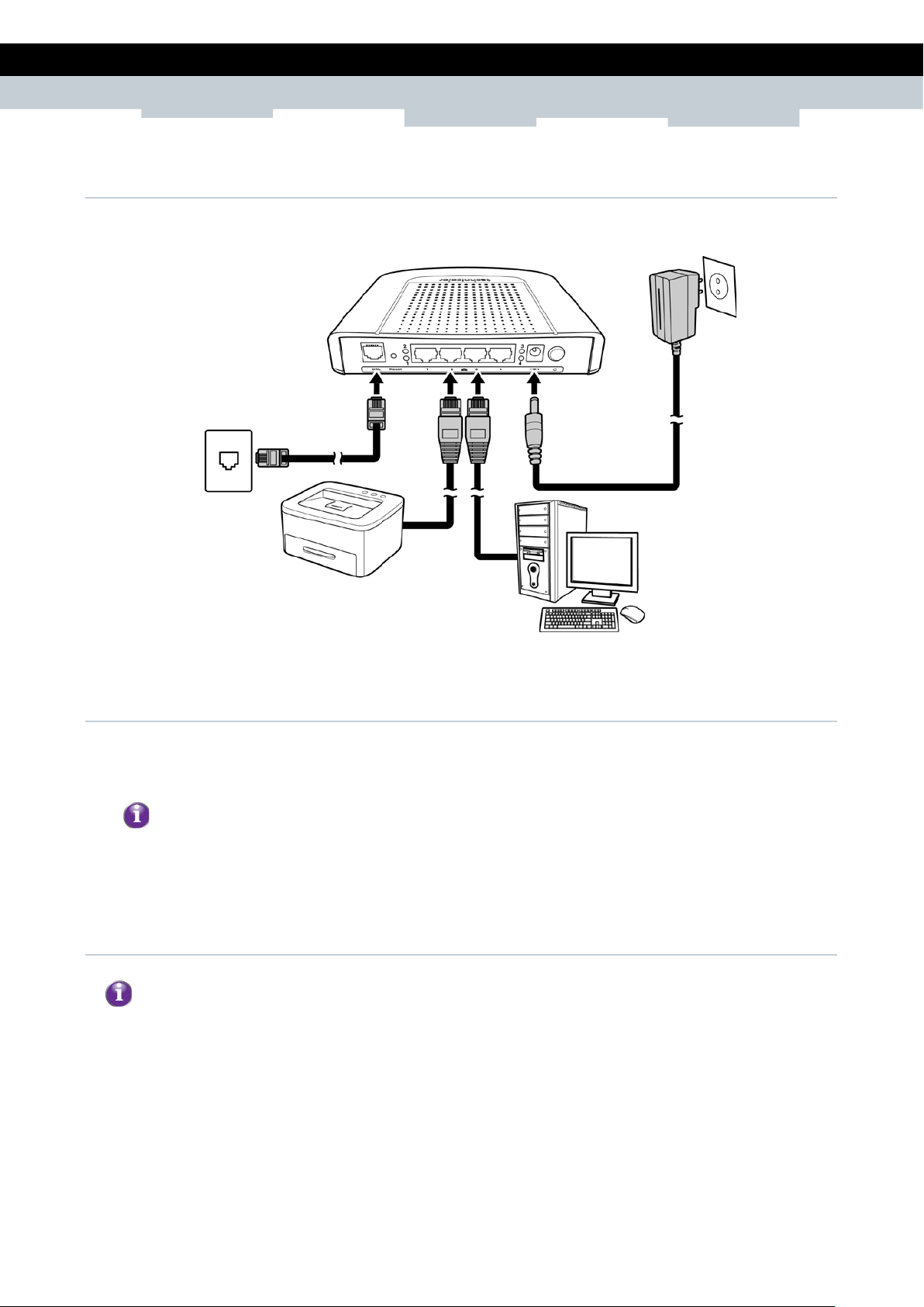
2 Installation
Make sure that all devices are powered off before starting installation.
Installation Diagram
2.1 Connec t the Power
1 Connect the power adapter to th e DC In jack of your Wireless Gateway.
2 Plug the power adapter to a wall outlet or a power strip.
Use only the supplied power adapter. Using other power adapters may cause damag e t o the
device.
outlet.
2.2 Connect Wired Devices
1 Connect one end of the RJ-45 cable to one of the Ethernet (1, 2, 3, 4) ports of your Wireless
Gateway.
et
2 Connect the other end of the RJ-45 cable to the Ethernet port of the computer.
3 Repeat the above steps to connect other computers to the Wireless Gateway via Ethernet
connection.
4 To connect more than four compu t e r s, use a hub or switch. Connect one end of an RJ-45 cable to the
hub or switch and the other end to the computer.
Copyright © 2012 Technicolor. All rights reserved.
DMS-CTC-20120508-0000 v1.0.
Page 8
8
SETUP & USER GUIDE
The SSID and passphrase are the ones you have s
Security Settings
2.3 Connect Wireless Devices
Before connecting wireless devices to the Wireless Gateway, configure th e wireless security settings of
your Wireless Gateway (see “To Set up Security Settings on page 41”). Take note of the SSID and the
password you have set, you need the SSID and the password to connect devices to your Wireless
Gateway.
2.3.1 WLAN
From the wireless device end, se arch for the Wireless Gateway network name (SSID), and enter the
passphrase to connect.
on page 41”).
et in the Wireless Security Settings (see “To Set up
2.3.2 Wi-Fi Protected Setup (WPS)
Press and hold the WPS button of the Wireless Gateway for at least 8 seconds and press the WPS button
on the WPS-enabled device to start pairing.
2.4 Connect the Broadban d (DSL)
1 Connect one end of the RJ-11 cable to the DSL port of your Wirele ss Gateway.
2 Connect the other end of the RJ-11 cable to a wall jack with DSL service.
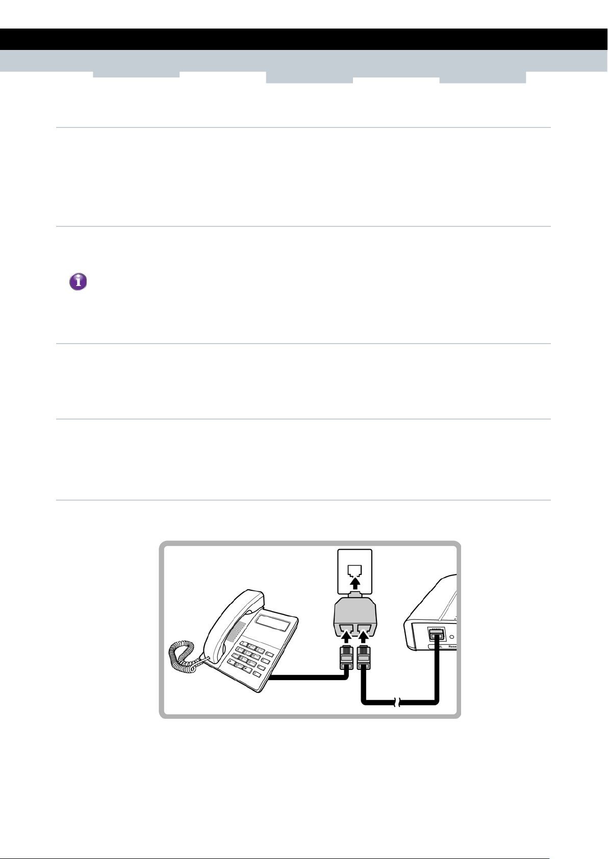
2.4.1 Use a Splitter
You need a splitter when connecting the Wireless Gateway to the wall jack that also connects to a
telephone.
1 Plug the splitter to the wall jack with DSL service.
2 Connect one end of the RJ-11 cable to the DSL port of your Wirele ss Gateway.
3 Connect the other end of the RJ-11 cable to the MODEM port of the splitter.
4 Connect the telephone to the LINE port of the splitter using another RJ-11 cable.
Copyright © 2012 Technicolor. All rights reserved.
DMS-CTC-20120508-0000 v1.0.
Page 9

9
SETUP & USER GUIDE
2.5 Check the Installation
To ensure that all devices are properly connected, check the LED indicators on the front of your
Wireless Gateway. For basic installation, the following LEDs must be l it:
▪ Power LED
▪ Ethernet LED
▪ DSL LED
The lighted LED indicators vary depending on the type of connection that you make. See “Front Panel”
on page 5 for more information about the LED indicators.
Copyright © 2012 Technicolor. All rights reserved.
DMS-CTC-20120508-0000 v1.0.
Page 10
10
SETUP & USER GUIDE
1
2
3
is checked. If not, check it to enable the
4
5
6
1
2
3
4
5
Obtain DNS
6
3 Configure the Computer
This chapter will guide you on h ow to configure your computer according to the op e r ating system you
are using.
▪ Windows
▪ Windows
▪ Windows
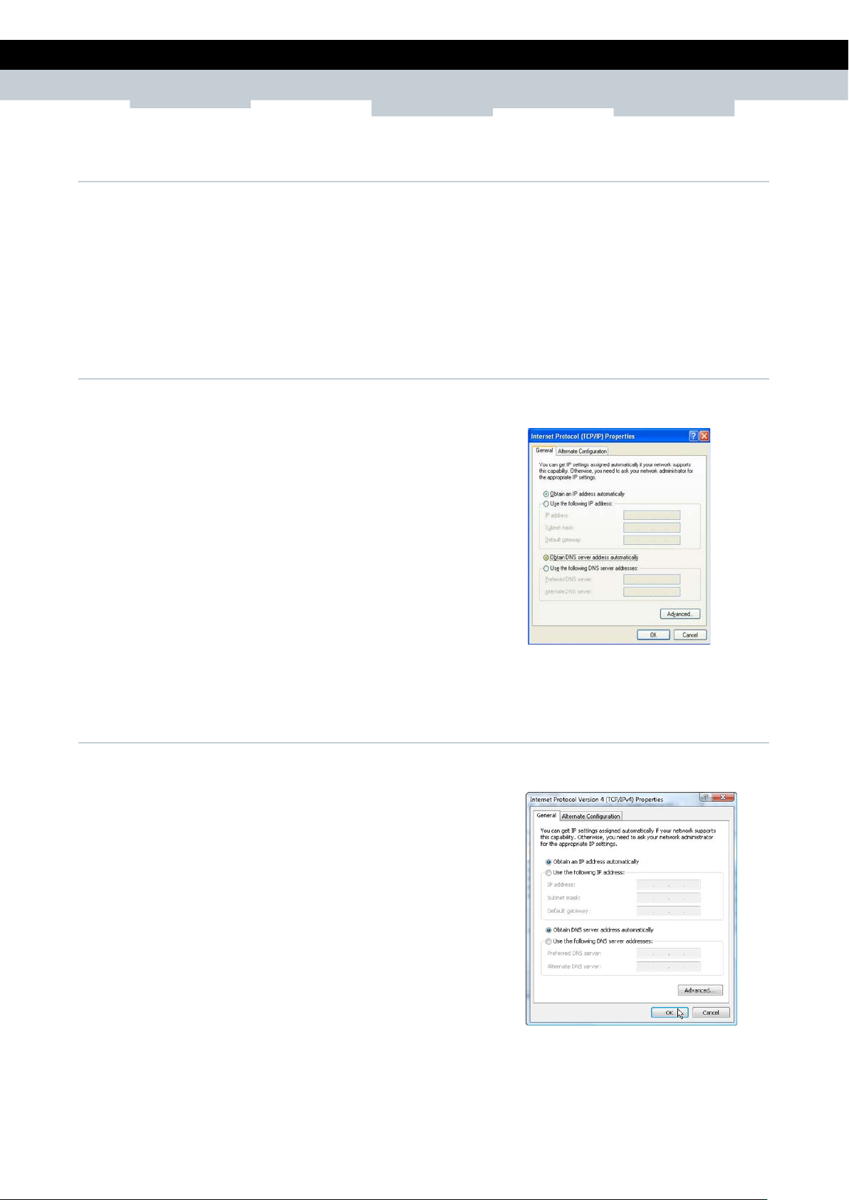
3.1 Windows XP
If you are using Windows XP, follow the instruction s below to configure your computer.
Click Start > Control Panel > Network Connections.
Right-click Local Area Connection, then click Properties.
XP, see below.
Vista, see page 10.
7, see page 11.
On the network components list, make sure that Internet
Protocol (TCP/IP)
Properties button.
Select Internet Protocol (TCP/IP), and then click
Properties.
On the General tab, select Obtain an IP Address
automatically and Obtain DNS server address
automatically.
Click OK.
General Page
3.2 Windows Vista
If you are using Windows Vista, follow the instructions below to configure your computer.
Click Start > Control Panel > Network and Internet
Connections > Network Connections.
Right-click Local Area Connection, then click Properties.
On the General tab, make sure that Internet Protocol
(TCP/IP) is checked. If not, check it to enable the
Properties button.
Select Internet Protocol (TCP/IP), and then click
Copyright © 2012 Technicolor. All rights reserved.
DMS-CTC-20120508-0000 v1.0.
Properties.
Select Obtain an IP Address automatically and
server address automatically.
Click OK.
General Page
Page 11
11
SETUP & USER GUIDE
1
2
3
4
is checked. If not, check it to enable the
5
6
7
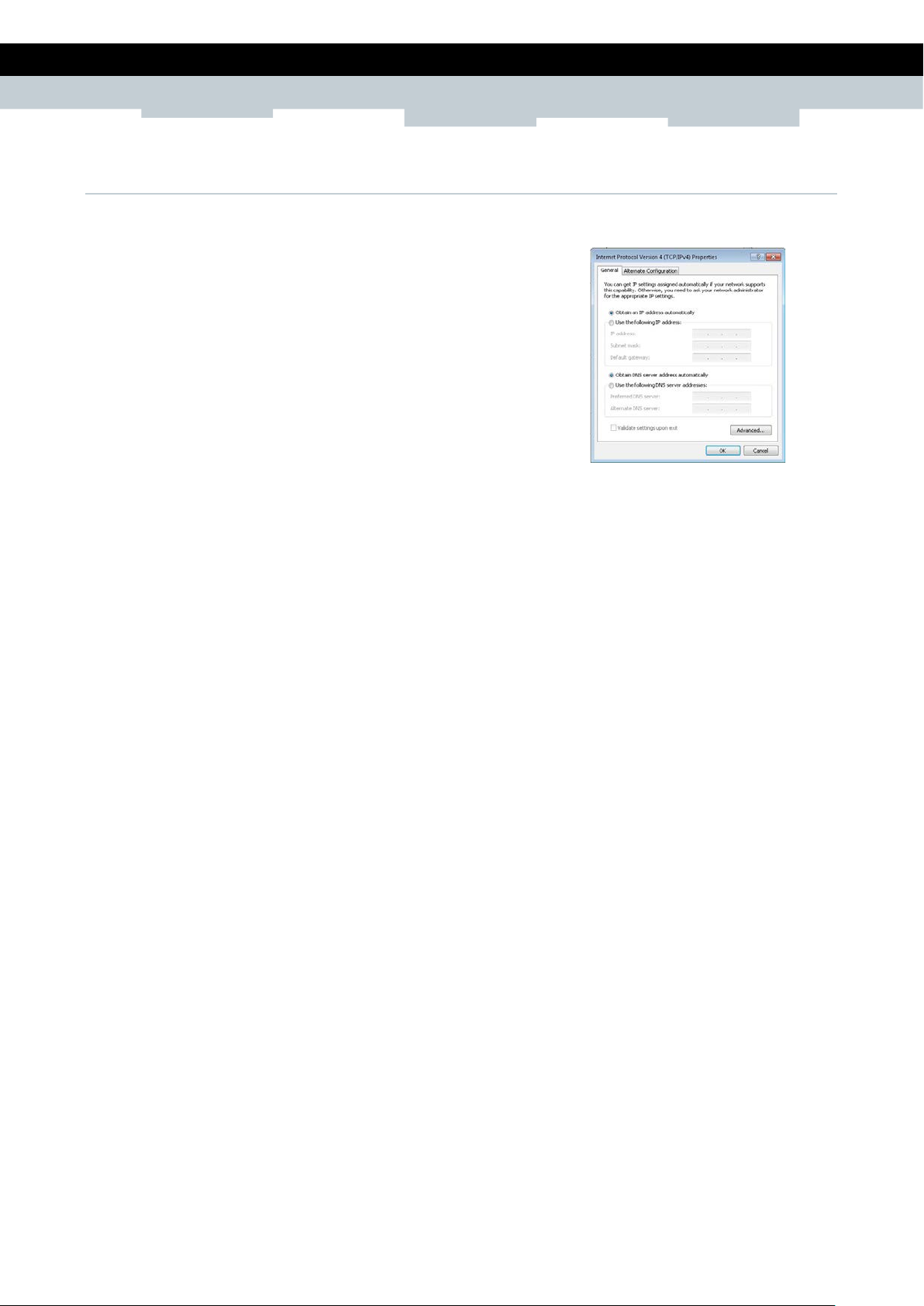
3.3 Windows 7
If you are using Windows 7, follow the instructions b e low to configure your computer.
Click Start > Control Panel > Network & Sharing Center.
Click Local Area Connection.
Click Properties.
On the network components list, make sure that Internet
Protocol (TCP/IP)
Properties button.
Select Internet Protocol (TCP/IP), and then click
Properties.
On the General tab, select Obtain an IP Address
automatically and Obtain DNS server address
automatically.
Click OK.
General Page
Copyright © 2012 Technicolor. All rights reserved.
DMS-CTC-20120508-0000 v1.0.
Page 12
12
SETUP & USER GUIDE
If the Web Configurations util it y has been left idle for some minutes, the syste m may prompt
you to login again; enter the
The default user name and passw or d is “admin”. It is
4 Access the Wireless Gateway
Use the Web Configurations ut ility to configure your Wireless Gateway.
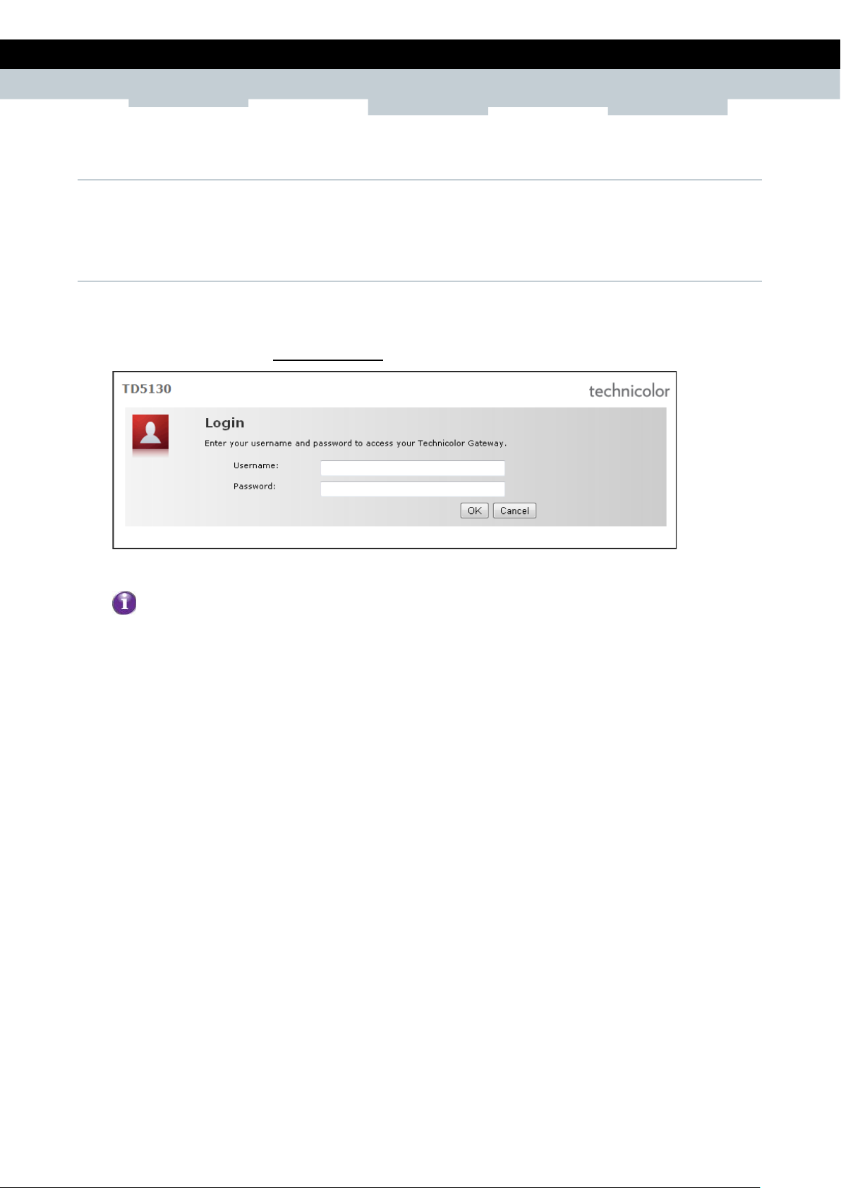
4.1 Login
For more advanced configuration, access the Technicolor web configurat ion utility.
1 Launch the web browser.
2 On the address bar, type http://192.168.1.1, and then press Enter.
3 Type the Username and Password, default values are “ad min”.
4 Click OK.
User name and Password.
advised to change the password.
Copyright © 2012 Technicolor. All rights reserved.
DMS-CTC-20120508-0000 v1.0.
Page 13
13
SETUP & USER GUIDE
4.2 The Interface
Once logged in, the Home screen appears. The Home screen provides quick access to t h e most common
functions of your Wireless Gateway. Click an option to access the function.
To quickly change passwords or switch users, click the user name on the top-left corner of the screen
(in the above example, “admin”). To change the menu language, click es for Spanish or en for English.
In some screens, shortcut items are available on the bottom of the screen. Click a shortcut to access
the page. See example below.
Copyright © 2012 Technicolor. All rights reserved.
DMS-CTC-20120508-0000 v1.0.
Page 14
14
SETUP & USER GUIDE
4.3 Using the Menu
For more advanced users, use th e main menu, located on the left panel of the screen, t o configure your
Wireless Gateway.
Click a menu item, then a submenu to display the page.
The following menu items are available:
▪ Home — Displays the Home screen.
▪ Technicolor Gateway — Allows you to configure your Wireless Gateway, such as system dat e and
time, and to view event logs.
▪ Broadband Connection — Allows you to view the DSL connection s tatus of your Wireless Gateway and
configure a dial-up connection and establish or terminate the Internet connection.
▪ Toolbox — Allows you to configure more advanced functions, such as remot e assistance, firewall,
filter, parental control serv ices, and others.
▪ Home Network — Allows you to view the devices connected to the network of your Wireless
Gateway.
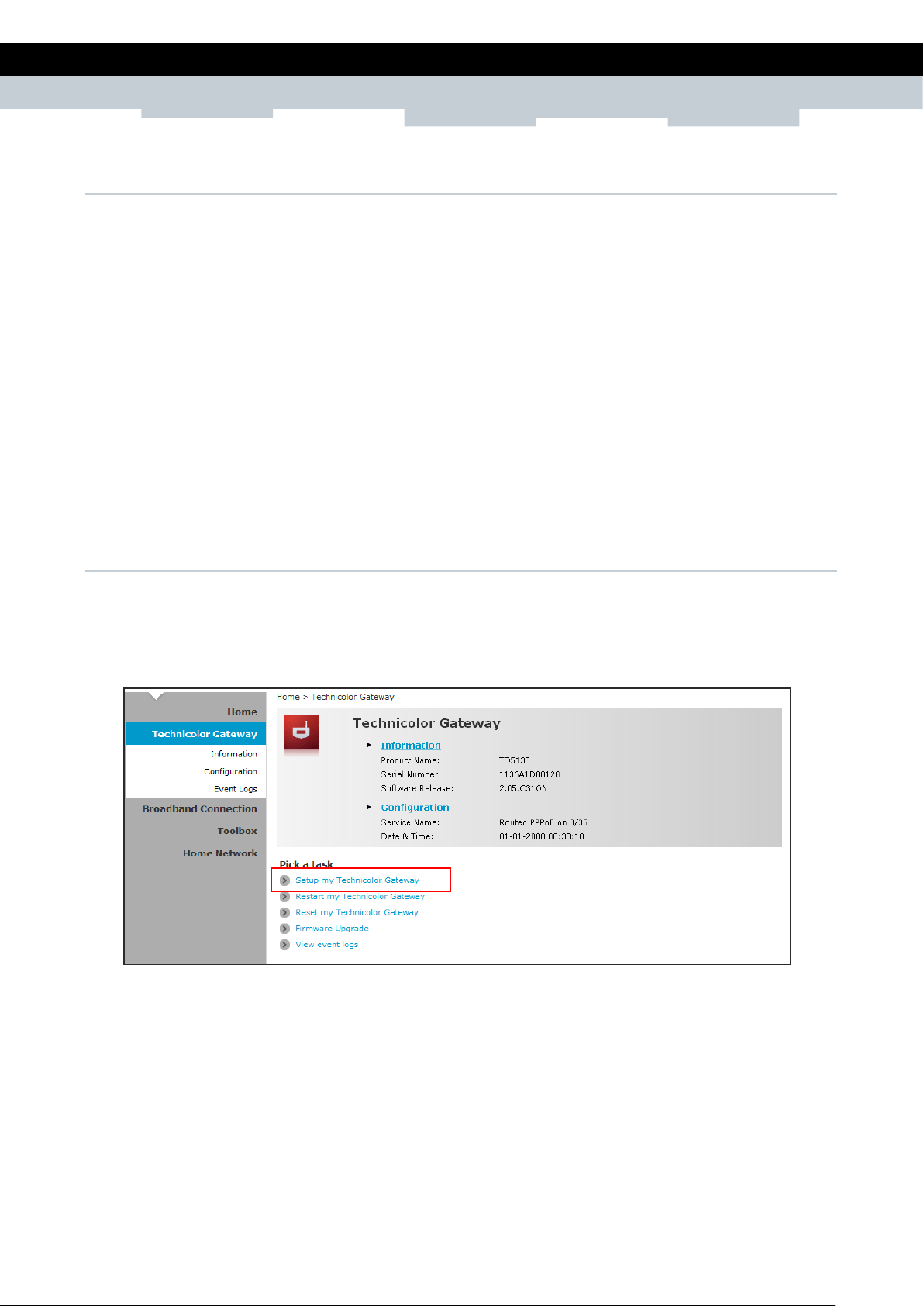
4.4 Configuration Wizard
For first time users, you may want to use the wizard to set up your Wireless Gat e way. Perform the
following:
1 On the main menu, click Technicolor Gateway.
2 Click the Setup my Technicolor Gateway shortcut at the bottom of the screen.
Copyright © 2012 Technicolor. All rights reserved.
DMS-CTC-20120508-0000 v1.0.
Page 15

15
SETUP & USER GUIDE
The required information on the succeeding screens
Service Provider (ISP).
3 The Technicolor Wizard screen appears. Click Next to continue.
4 Select the DSL account service: Bridge, Routed PPP, or Routed IP. Then click Next.
If you select Routed PPP, skip to step 6.
If you select Routed IP, skip to step 7.
must be obtained from your Internet
Copyright © 2012 Technicolor. All rights reserved.
DMS-CTC-20120508-0000 v1.0.
Page 16

16
SETUP & USER GUIDE
5 If you select, Bridge, do the following:
a Select the VPI/VCI, and then click Next.
b If your network is using a DHCP server, keep the DHCP Server box checked, if not, remove it.
c Click Next to continue. Then, skip to step 8.
Copyright © 2012 Technicolor. All rights reserved.
DMS-CTC-20120508-0000 v1.0.
Page 17

17
SETUP & USER GUIDE
6 If you select Routed PPP, do the following:
a Select the VPI/VCI and Connection Type, and then click Next.
b The Internet Account Settings screen appears. Obtain the necess ary information from your ISP.
c Type your Internet account user name in User Name.
d Type your account password in Password and Confirm Password.
e Click Next to continue.
Copyright © 2012 Technicolor. All rights reserved.
DMS-CTC-20120508-0000 v1.0.
Page 18

18
SETUP & USER GUIDE
7 If you select Routed IP, do the following:
a Select the VPI/VCI and Connection Type, and then click Next.
b The Internet Account Settings screen appears. Obtain the necessar y information from your ISP.
c Type External I P Address, S ubnet Mask, and Default Gat eway.
d Click Next to continue. Then, skip to step 8.
Copyright © 2012 Technicolor. All rights reserved.
DMS-CTC-20120508-0000 v1.0.
Page 19

19
SETUP & USER GUIDE
e Type the IP address of the DNS servers, and then click Next.
8 Review your Wireless Gateway settings, and then click Start to apply the settings.
Bridge Connection Routed PPP Connection Routed IP Connection
9 The configuration may take a while to finish. When complete, click Finish.
10 Close the web browser.
Copyright © 2012 Technicolor. All rights reserved.
DMS-CTC-20120508-0000 v1.0.
Page 20

20
SETUP & USER GUIDE
5 Technicolor Gateway
The Technicolor Gateway menu allows you to view th e system information and configure the Wireless
Gateway. This menu is divided in t o three sections: Information, Configuration, and Event Logs.
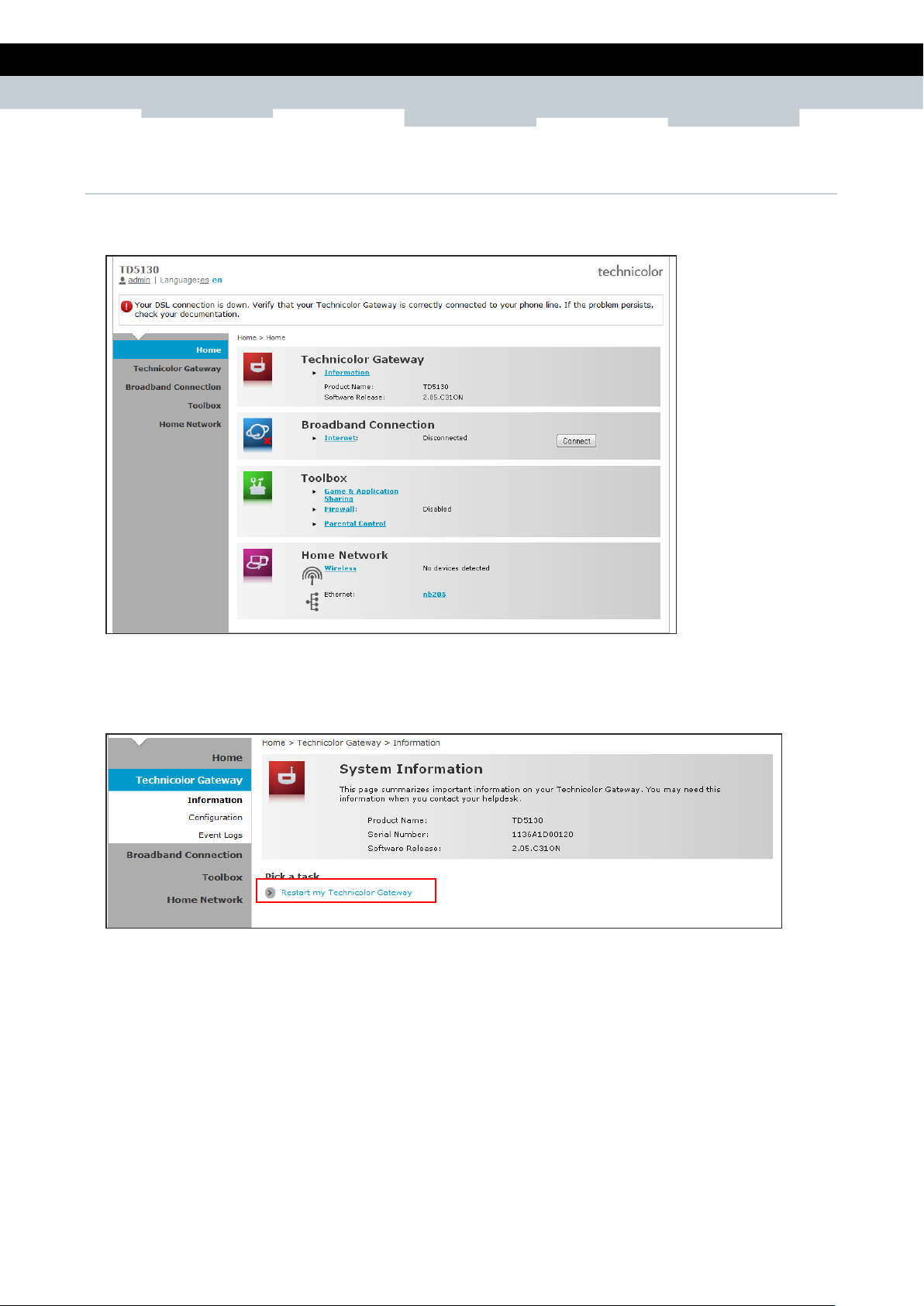
5.1 System Information
The System Information page di sp lays the product name, device serial number, and software release
information. To view the System Information page, do one of the following:
1 On the main menu, click Technicolor Gateway > Information.
2 From the Home screen, click Information.
Copyright © 2012 Technicolor. All rights reserved.
DMS-CTC-20120508-0000 v1.0.
Page 21

21
SETUP & USER GUIDE
5.2 System Configuration
The System Configuration page allows you to configure the Internet service and the system date and
time, and enable web browsing interception.
To view the System Configuration page, click Technicolor Gateway > Configuration.
To modify the system configuration, click Configure.
5.2.1 DSL Service Configuration
To modify the DSL service configuration, click Configuration Wizar d and then follow the instructions on
the screen. See “Configuration Wizard on page 14”.
5.2.2 Date and Time Configuration
To modify the time configuration, do the one of following:
Manual Configuration
To manually set the date and time, enter the date and time values in the corresponding fields. Select a
Timezone or enable Summer Time for applicable areas.
Auto Configuration
To synchronize the date and time wit h a time server, do the following:
1 Check the Auto-configuration box.
2 Enter the values of the applicable items in your location:
Timezone — Enter the time zone in your location.
Summer Time — Check if summer time is applicable in your location.
3 Enter the time server to sync the Wireless Gateway with. You can t ype up to five timer servers.
4 Click Apply to save changes.
Copyright © 2012 Technicolor. All rights reserved.
DMS-CTC-20120508-0000 v1.0.
Page 22

22
SETUP & USER GUIDE
5.2.3 Web Browsing Interception
1 On the Web Browsing Interception box, select one of the following:
Enabled (default) — To enable web browsing interception.
Disabled — To disable web browsing interception. When disabled, address based filtering is also
disabled.
2 Click Apply to save changes.
5.3 Event Logs
The Event Logs page allows you to view an d clear system logs.
To access the Event Logs page, click Techn icolor Gateway > Event Logs.
You can filter the list by sele cting a category from the drop-down lists.
The log is automatically re fr e shed every 10 seconds.
To clear the log, click Clear the event log on the bottom of the page.
Copyright © 2012 Technicolor. All rights reserved.
DMS-CTC-20120508-0000 v1.0.
Page 23

23
SETUP & USER GUIDE
DSL connection cannot be modif ie d from this point. To modify the DSL connection, se e “
DSL
Service Configuration
6 Broadband Connection
The Broadband Connection menu allows you to view and modify the Internet service configuration of
your Wireless Gateway. This menu is divided into two sections: DSL Connection and Internet Services.
To view the Broadband Connect ion page, click Broadband Connection.
6.1 DSL Con ne ction
To view the DSL connection status, do one of the following:
▪ On the Broadband Connection page, click View more under DSL Connection.
▪ On the main menu, click Broadband Connection > DSL Connection.
on page 21”.
5.2.1
Copyright © 2012 Technicolor. All rights reserved.
DMS-CTC-20120508-0000 v1.0.
Page 24

24
SETUP & USER GUIDE
6.2 Internet S ervices
Use the Internet Services page to configure the settings and connect to the Internet. To view the
Internet page, do one of the followin g:
▪ From the Home screen, click Internet
▪ On the Broadband Connection page, click View more under Internet.
▪ On the main menu, click Broadband Connection > Internet Services > View More
To connect to the Internet, click Connect.
To modify the account username and password, re-ty p e the information on the corresponding
boxes, and then click Connect.
To view more connection details, click Details on the upper corner of the page.
Copyright © 2012 Technicolor. All rights reserved.
DMS-CTC-20120508-0000 v1.0.
Page 25

25
SETUP & USER GUIDE
To enable remote assistance, you must be connected to the Interne
▪
▪
7 Toolbox
The Toolbox menu allows you t o p r otect your network, share games and applicat ions with other people
on the Internet, and manage your local network. This menu is divided into eight sections: Remote
Assistance, Game & Application Sharing, Parental Control, Firewall, Intrusion Detection, Dynamic
DNS, User Management, and DMZ.
To view the Toolbox page, click Toolbox on the main menu.
7.1 Remote Assistance
The Remote Assistance page allows you t o make your Wireless Gateway remotely accessible.
t.
7.1.1 Enable Remote Assistance
1 Select the remote assistance Mode:
Permanent Mode — Once remote assistance is enabled, the remote session only ends when users
disable this feature or when the Wireless Gateway is restarted.
Temporary Mode — The remote session automatically ends after 20 minutes of inactivity.
2 Enter the URL address to use to remotely access your Wireless Gateway.
3 Take note of the automatically generated User Name and Password that will be used t o access your
Wireless Gateway remotely. If desired, modify the password.
4 Check Enable Remote Assistance to enable this function.
5 Click Apply to save changes.
Only one remote session is allowed at a time.
The Wireless Gateway also sup p or ts dynamic DNS host names for remote access. See "7.6
Dynamic DNS" on page 33.
Copyright © 2012 Technicolor. All rights reserved.
DMS-CTC-20120508-0000 v1.0.
Page 26

26
SETUP & USER GUIDE
7.1.2 Disable Remote Assistance
Click Disable Remote Assistance to disable this function.
7.2 Game & Appl ication Sharing
The Game & Application Sharing page allows you to create new games and applications and assign
games or applications to the network devices.
To view the Game & Application Sharing page, do one of the following:
▪ From the Home screen, click Game & Application Sharing under Toolbox.
▪ On the main menu, click Toolbox > Game & Application Sharing.
Copyright © 2012 Technicolor. All rights reserved.
DMS-CTC-20120508-0000 v1.0.
Page 27

27
SETUP & USER GUIDE
7.2.1 Assign a Game or Application
Your Wireless Gateway comes with predefined games and applications. Each game or application can be
assigned to a network device.
1 To assign a game or application , do one of the following:
Click Configure on the upper-right corner of the screen.
Click the Assign a game or application to a local network device shortcut at the bottom of the
screen.
2 To enable Universal Plug and Play (UPnP) function, check the Use UPnP box, then click Apply.
3 On the Assigned Games & Applications table, select a game or application on the Game or
Application field.
4 On the Device field, select the network device to assign the game or application to.
5 To log access, check the Log box.
6 Click Add to add the assigned entry to the table.
Copyright © 2012 Technicolor. All rights reserved.
DMS-CTC-20120508-0000 v1.0.
Page 28

28
SETUP & USER GUIDE
7.2.2 Modify Assigned Game or Application
1 On the main menu, click Toolbox > Game & Application Sharing.
2 From the Game & Application page, click Configure on the upper-right corner of the screen.
3 On the Assigned Games & Applications table, click the Edit button of the game or application you
want to modify.
4 Modify the necessary info.
5 Click Apply to save changes.
7.2.3 Create a New Game or Application
If the game or application is not included in the predefined list, you need to create the game or
application.
1 On the main menu, click Toolbox > Game & Application Sharing.
2 From the Game & Application page, click the Create a new game or application shortcut at the
bottom of the screen.
3 On Name, type the name of the game or application.
Copyright © 2012 Technicolor. All rights reserved.
DMS-CTC-20120508-0000 v1.0.
Page 29

29
SETUP & USER GUIDE
4 Select how you want to define the new game or application:
Clone Exiting Game or Application — Select an existing game or application to clone its protocol
and TCP/UDP port range settings.
Manual Entry of Port Maps — To manually select the protocol and enter the port range of the new
game or application.
5 Click Next to continue.
6 If Clone Exiting Game or Application is selected on step 4, skip to step 8.
7 If Manual Entry of Port Maps is selected on step 4, configure the paramet e rs of the Game or
Application Definition table. A preset incoming port range is set by the Wireless Gateway. You may
add, edit, or delete this range. To add a TCP/UDP port range, do the following:
a Select the protocol.
b Enter the incoming port range and the outgoing trigger port.
c Click Add to save the settings.
8 Creating of game or application is complete.
7.2.4 Modify a Game or Application
1 On the main menu, click Toolbox > Game & Application Sharing.
2 From the Game & Application page, click the Modify a game or application shortcut at the bottom
of the screen.
3 The list of games and applications appear. Click the Edit button of the game or application you want
to modify.
4 Modify the necessary infor mation.
5 Click Apply to save changes.
To delete a game or application, click the Delete button of the game or application you want to delete.
Copyright © 2012 Technicolor. All rights reserved.
DMS-CTC-20120508-0000 v1.0.
Page 30

30
SETUP & USER GUIDE
7.3 Parenta l C o ntrol
The Parental Control page all ows you to filter web sites that a network device may access or be denied
access.
To view the Parental Control page, do one of the following:
▪ From the Home screen, click Parental Control under Toolbox.
▪ On the main menu, click Toolbox > Parental Control.
To configure parental control, click Configure on the upper-right corner of the screen.
▪ Use Address Based Filter — Check to filter web sites by address.
▪ Actionfor Unknown Sit es — Select whether to Block or Allow unknown sites.
▪ Click Apply to save changes.
▪ Web Site — Enter the URL of the web site to block or allow.
▪ Action — Select one of the following option s:
Block: To block the web site.
Allow: To allow access to the web site.
Redirect: To redirect to another web site if the web site defined on the Web Site field is being
accessed.
▪ Redirect — If Redirect is selected in Action, enter the URL address to where you want to redirect
the site.
▪ Click Add to save the changes to the table.
Copyright © 2012 Technicolor. All rights reserved.
DMS-CTC-20120508-0000 v1.0.
Page 31

31
SETUP & USER GUIDE
7.4 Firewall
The Firewall page allows you to set the firewall security of your Wireless Gateway.
To view the Firewall page, do one of the following:
▪ From the Home screen, click Firewall under Toolbox.
▪ On the main menu, click Toolbox > Firewall.
7.4.1 Change Firewall Security Level
1 On the Firewall page, click Configure on the upper-right corner of the screen.
2 Select the desired security level:
Block All — Block all traffic from and to the Internet.
Standard — Block all incoming traffic but allow outgoing traffic.
Disabled — Disable firewall security, all traffic is allowed.
3 Click Apply to save changes.
7.4.2 Create a New Security Level
1 On the Firewall page, click Configure on the upper-right corner of the screen.
2 Click the Create a new Security Level shortcut at the bottom of the screen. The New Firewall Level
screen appears.
3 Enter the name for the new firewall security level.
4 Select a security level.
5 Click Apply to save changes.
Copyright © 2012 Technicolor. All rights reserved.
DMS-CTC-20120508-0000 v1.0.
Page 32

32
SETUP & USER GUIDE
7.4.3 Set Filter Rules
After you create a new security level, you can set firewall rules.
1 On the Firewall page, click Configure on the upper-right corner of the screen.
2 Click Edit. The Firewall Settings appears.
3 On the Firewall Settings table, click Add.
4 Enter the necessary parameters:
Name — Enter desired firewall rule name
Enabled — Check this box to enable this firewall rule.
Source Interface — Select the interface to apply the firewall rule.
Source Address — Select the firewall source address.
User-Defined — If the address is not listed in the Source Address box, enter a user-defined address
here.
Destination Interface — Select the destination interface.
Destination address — Select the destination address.
User-Defined — If the address is not listed in the Destination Address box, enter a user-defined
address here.
Service — Select a service.
Action — Select the action to take: Deny or Accept.
5 Click Apply to save changes. The new firewall rule appears on the Firewall Settings table.
To edit a firewall rule, click Edit.
To delete a firewall rule, click Delete.
Copyright © 2012 Technicolor. All rights reserved.
DMS-CTC-20120508-0000 v1.0.
Page 33

33
SETUP & USER GUIDE
7.5 Intrusio n De te ction
Your Wireless Gateway prot e ct s your network against malicious intrusions. T h e Intrusion Detection
page shows you the intrusions t hat you are protected against. The Protected Intrusions table shows the
number of times the Wireless Gateway actively protected your network against each intrusions.
To view the Intrusion Detection page, on the main menu, click Toolbox > Intrusion Detection.
7.6 Dynamic DNS
The Dynamic DNS (DDNS) service allows you to assign a fixed DNS host name to an Internet connection
even if it is using a dynamic IP ad d r e ss. As soon as your Wireless Gateway internal connection gets a
new IP address, the dynamic DNS service updates the host name entry to the new IP address. The
dynamic DNS service relies on se r v ers that link the public IP address to a subscribed DNS host name.
To view the Dynamic DNS page, on the main menu, click Toolbox > Dynamic DNS.
In order to use a dynamic DNS service, you must first register and enroll for DNS service with a Dynamic
DNS service provider. The DDNS service provider will provide the necessary parameters to complete
your Wireless Gateway Dynamic DNS setup.
To configure the Dynamic DNS ser vice of your Wireless Gateway, click Configure on the upper-right
corner of the screen.
▪ Enabled — Check this box to enable the DDNS.
▪ Interface — The DDNS interface is the Internet.
▪ Username — Enter the username provided by the DDNS service provider.
▪ Password — Enter the password provided by the DDNS service provider.
Copyright © 2012 Technicolor. All rights reserved.
DMS-CTC-20120508-0000 v1.0.
Page 34

34
SETUP & USER GUIDE
▪ Confirm Password — Re-type the password to conf irm.
▪ Service — Select the DDNS service provider where your account is registered.
▪ Host — Type the host name.
Click Apply to save changes.
To use multiple hosts, click the Use multiple hosts shortcut at the bottom of the screen. Then click
Add to add host name.
7.7 User Management
The User Management page allows you to configure the users who can access the Wireless Gatew ay
web configuration utility.
To view the User Management page, click Toolbox > User Management.
7.7.1 Add New User
1 Click the Add new user shortcut at the bottom of the screen.
2 On Name, type desired user name. This will be the login name and the password of the new user.
3 On Administrator Privileges, select the user privilege.
4 Click Apply to save changes.
7.7.2 Reset Password
To reset a password, on the User Management screen, click on the user account that you want to reset
the password. Then click Reset Passw ord.
Aside from resetting the pas sword, no other setting can be modified unless by users of higher privileges.
7.7.3 Manage Users
To change the default user, click the Set the default user shortcut at the bottom of the screen.
To switch to another user, click the Switch to another user shortcut at the bottom of the screen. This
brings you back to the login page, then login with the desired user account.
Copyright © 2012 Technicolor. All rights reserved.
DMS-CTC-20120508-0000 v1.0.
Page 35

35
SETUP & USER GUIDE
7.8 DMZ
The DMZ page allows you to configure a computer, called the DMZ host, on your network to have
unrestricted Internet access. This function is useful for gaming purposes. However, this places the DMZ
outside the firewall and is expo se d to security risks.
To assign a DMZ host, do the foll owing:
1 On the main menu, click Toolbox > DMZ.
2 Click Configure on the upper-right corner of the screen.
3 Check the Status box to enable the DMZ host function.
4 On IP Address, type the IP address of the computer you want to assign as the DMZ host.
5 Click Apply to save changes.
Copyright © 2012 Technicolor. All rights reserved.
DMS-CTC-20120508-0000 v1.0.
Page 36

36
SETUP & USER GUIDE
8 Home Network
The Home Network menu displays the network configuration of your Wireless Gateway, along with
interfaces and connected devi ce s. This menu is divided into two sections: Devices and Interfaces.
To view the Home Network page, click Home Network on the main menu.
8.1 Devices
This page displays the device s con nected on your network via the Wireless Gateway Ethernet ports. You
can do the following:
▪ View the device information, IP address and connection services
▪ Assign a public IP address to a de vice
To access the Devices page, click Home Network > Devices.
8.1.1 View or Modify Device Information
1 Click the device name. The device information is displayed on screen.
2 To modify the device information, click Configure on the upper right corner of the screen.
3 Type desired device name in New Name.
4 Select the device type in Type.
5 To assign a static IP address, che ck the Always use the same IP address box.
6 Click Apply to save changes.
Copyright © 2012 Technicolor. All rights reserved.
DMS-CTC-20120508-0000 v1.0.
Page 37

37
SETUP & USER GUIDE
8.1.2 Assign Game or Application to Device
1 Click the device name. The device information is displayed on screen.
2 Click Configure on the upper-right corner of the screen.
3 On the Connection Sharing section, select the game or application on the table.
4 Click Add.
8.1.3 Remove a Shared Game or Application
1 Click the device name. The device information is displayed on screen.
2 Click Configure on the upper-right corner of the screen.
3 On the Connection Sharing se ction, click the corresponding Unassign button of to remove the shared
game or application.
8.1.4 Assign a Public IP Address to Device
The Assign Public IP page allows you to assign the public IP address of your Internet connection to a
specific device on your local ne t work.
1 Cick Home Network > Devices.
2 Click the Assign the public IP address of a con nection to a device shortcut. The Assign Public IP
screen appears.
3 Click Edit.
4 On Device, select the network device that you want to assign the public IP address.
5 Click Apply.
Or, to remove the assigned IP address from a network device, click Unassign.
Copyright © 2012 Technicolor. All rights reserved.
DMS-CTC-20120508-0000 v1.0.
Page 38

38
SETUP & USER GUIDE
8.2 Interfaces
The Interfaces page allows you to configure the network device TCP/IP settings such as IP address
subnet mask, assign a DHCP server , and configure the wireless network secu r ity settings.
To view the Interfaces page, click Home Network > Interfaces.
8.2.1 Local Network Interface
Click Home Network > Interfaces > LocalNetwork to open the Local Network page.
This page displays the interface information including the TCP/IP configu r ation, IP Addresses, DHCP
pool. To modify the settings, click Configure on the upper-right corner of the screen.
To use a DHCP Server, check the Use DHCP Server box, then click Apply.
To Add an IP Address
1 On the IP Addresses table, type the IP address you want to add on the first box.
2 Type the subnet mask on the second box.
3 Click Add.
To Modify the IP Address
1 On the IP Addresses table, click the corresponding Edit button of the IP address you want to modify.
2 Modify the IP address (first box) and the subnet mask (second box).
3 Click Apply to save changes.
Copyright © 2012 Technicolor. All rights reserved.
DMS-CTC-20120508-0000 v1.0.
Page 39

39
SETUP & USER GUIDE
To Modify the DHCP Pool
1 Click the Edit button of the pool you want to mod ify. The LAN_Private screen appears.
Interface — Displays the current network interface.
Start Address — Type the starting address of the DHCP pool.
End Address — Type the ending address of the DHCP pool.
Subnet Mask — Type the subnet mask.
Gateway — Type the gateway.
Primary DNS — Type the primary DNS.
Secondary DNS — Type the secondary DNS.
Always give same address to DHCP clients — Check to always give the same address f or all DHCP
clients. Otherwise, remove the check.
2 When done, click Apply.
8.2.2 Wireless Access Point
Click Home Network > Interfaces > WLAN to open the Wireless Access Point page.
This page displays the information of your wireless network. To view the adv anced settings, click
Details on the upper-right corner of the screen.
Copyright © 2012 Technicolor. All rights reserved.
DMS-CTC-20120508-0000 v1.0.
Page 40

40
SETUP & USER GUIDE
To Configure the Wireless Network
1 Click Configure on the upper-right corner of the screen.
2 Enter or take note of the follow ing information:
Interface Enabled — Check to enable the wireless access point.
Physical Address — Displays the MAC address of the wireless device.
Network Name (SSID) — Enter desired wireless network name. This is the name shown to other
wireless devices to connect t o your network.
Actual Speed — Displays the network speed
Band — Displays the channel band.
Channel Selection — Select the automatic or manual channel selection.
Region — Displays your current region.
Channel — If Channel Selection is set to manual, select the channel from the list.
3 If necessary, configure the se cu rity settings, see "To Set up Security Settings" on page 41 .
4 If necessary, set up MAC filter. See "To Set up MAC Filter" on page 42.
5 Click Apply to save changes.
Copyright © 2012 Technicolor. All rights reserved.
DMS-CTC-20120508-0000 v1.0.
Page 41

41
SETUP & USER GUIDE
To Set up Security Settings
1 Click Home Network > Interfaces > WLAN to open the Wireless Access Point page.
2 Click Configure on the upper-right corner of the screen.
3 Under the Security section, check the Broadcast Network Name to enable wireless devices to see
the SSID of your wireless network.
4 On Encryption, select an encryption method:
Disabled — No encryption.
Use WEP Encryption — To use WEP encryption.
▪ WEP Key Length — Select the key length.
▪ WEP Encryption Key — Type the desired encryption key. Users need to enter this passkey to
connect to the wireless network.
Use WPA-PSK Encryption — To use a WPA-PSK encryption for more security.
▪ WPA-PSK Preshared Key — Type the desired passkey. Users need to enter this passkey to
connect to the wireless network.
▪ WPA-PSK Version — Select the WPA-PSK version to use.
5 Click Apply at the bottom of the page to save changes.
Copyright © 2012 Technicolor. All rights reserved.
DMS-CTC-20120508-0000 v1.0.
Page 42

42
SETUP & USER GUIDE
To Set up MAC Filter
1 Click Home Network > Interfaces > WLAN to open the Wireless Access Point page.
2 Click Configure on the upper-right corner of the screen.
3 Under the MAC Filter section, MAC address field, type the MAC address of a device to add to the
MAC filter.
4 Click Add. The MAC address is displayed on the MAC List table below. Repeat step 3 and 4 to add
more MAC addresses.
5 On Restrict Mode, select the restriction mode:
Disable — To disable the MAC filter.
Deny — To deny Internet access to devices with MAC address listed on the MAC List table.
Allow — To allow Internet access only to devices with MAC ad d res s listed on the MAC List table.
6 Click Apply to save changes.Appendix
Copyright © 2012 Technicolor. All rights reserved.
DMS-CTC-20120508-0000 v1.0.
Page 43

43
SETUP & USER GUIDE
Appendix A Wireless Considerations
Connection Performance
A number of factors affect wir e less connections. To ensure high-range and stable con nectivity, do the
following:
1 Keep the Wireless Gateway and other wireless devices away from obstructions, such as walls or
buildings. Each obstruction can reduce the range of a wireless device.
2 Keep the Wireless Gateway and other wireless devices away from devices that p r od uce radio
frequency (RF) noise, such as m icrowave ovens or radios.
3 Keep the Wireless Gateway and other wireless devices away from any device op e r ating on the 2.4GHz
frequency, such as cordless ph ones or remote controls.
Security Checklist
Wireless network signals can be intercepted easily. To prevent unauthorized users from connecting to
your wireless network, follow the guidelines below.
1 Change the default wireless network name.
2 Your device has a default Service Set Identifier (SSID) which is the wireless net work name. Change
the SSID with a unique name to identify your network. The SSID can be up to 32 characters in length.
3 Change the default password.
4 Your device has a default password. You have to enter this password to chang e your network
settings. Change the password to prevent unauthorized users from hacking into your network and
changing the settings.
5 Enable MAC address filtering.
6 Your device supports Media Access Control (MAC) address filtering. You can assign a MAC address on
each computer that you want to connect to your wireless network. When MAC address filtering is
enabled, only the computers with the specified MAC addresses are allowed acce ss.
7 Enable encryption
8 Your device supports Wired Eq uivalent Privacy (WEP), and Wi-Fi Protected Acc e ss (WAP/WPA2)
encryption. To ensure a high level of security, enable the highest security encryption and use strong
passphrases, avoid using wor d s t hat can be found in the dictionary.
Copyright © 2012 Technicolor. All rights reserved.
DMS-CTC-20120508-0000 v1.0.
Page 44

44
SETUP & USER GUIDE
Appendix B Regulatory & Safety Information
Wireless LAN, Health and Authorization
Radio frequency electromagnetic energy is emitted from Wireless LAN dev ices. The energy levels of
these emissions however ar e far much less than the electromagnetic energy emissions from wireless
devices like for example mob ile phones. Wireless LAN devices are safe for use frequency safety
standards and recommendations. The use of Wireless LAN devices may be restricted in some situations
or environments for exampl e :
▪ Onboard airplanes, or
▪ In an explosive environment, or
▪ In case the interference risk to other devices or services is perceived or identified as harmful
In case the policy regarding t he use of Wireless LAN devices in specific organizations or environments
(e.g. airports, hospitals, c hemical/oil/gas industrial plants, privat e b uildings etc.) is not clear, please
ask for authorization to use these devices prior to operating the equipment.
Disclaimers
Installation and use of this Wireless LAN device must be in strict accordance with the instructions
included in the user documentation provided with the product. Any changes or modifications made to
this device that are not expressly approved by the manufacturer may void the user’s authority to
operate the equipment. The Manufacturer is not responsible for any radio or television interference
caused by unauthorized modification of this device, of the substitution or attachment. Manufacturer
and its authorized resellers or distributors will assume no liability f or an y damage or violation of
government regulations arising from failing to comply with these guidelines.
FCC (Federal Communications Commission) Statement
This equipment has been tested an d found to comply with the limits for a Class B digital device,
pursuant to Part 15 of the FCC Rules. These limits are designed to provide reas on ab le protection
against harmful interference in a residential installation. This equipment generates, uses and can
radiate radio frequency energy and, if not installed and used in accordance with the instructions, may
cause harmful interferenc e to radio communications. However, there is no guarantee that interference
will not occur in a particular installation. If this equipment does cause harmful interference to radio or
television reception, which can be determined by turning the equipment off and on, the user is
encouraged to try to correct the interference by one of the following measures:
▪ Reorient or relocate the receiving antenna.
▪ Increase the separation between the equipment and receiver.
▪ Connect the equipment into an outlet on a circuit different from that to which the receiver is
connected.
▪ Consult the dealer or an experienced radio/TV technician for help.
FCC Caution: Any changes or modificati on s not expressly approved by the party responsible for
compliance could void the user’s authority to operate this equipment. This device complies with Part 15
of the FCC Rules. Operation is subject to the following two conditions:
1 This device may not cause interfere nce, and
2 This device must accept any interf e r ence, including interference that my cause unde sired operation
of this device.
Copyright © 2012 Technicolor. All rights reserved.
DMS-CTC-20120508-0000 v1.0.
Page 45

45
SETUP & USER GUIDE
IMPORTANT NOTE:
FCC Radiation Exposure Statement:
This equipment complies wit h FC C radiation exposure limits set forth for an uncontrolled environment.
This equipment should be installed and operated with minimum distance 20cm between the radiator &
your body.
This transmitter must not be co-located or operating in conjun ction with any other antenna or
transmitter.
The availability of some spe cific channels and/or operational frequen cy bands are country dependent
and are firmware programmed at the factory to match the intended destination. The firmware setting
is not accessible by the end user.
CE statement
Europe – EU Declaration of Conformit y
This device complies with the e sse ntial requirements of the R&TTE Directive 199 9/5/EC. The following
test methods have been applied in order to prove presumption of conformity with the essential
requirements of the R&TTE Directive 1999/5/EC:
EN60950-1: 2006
Safety of Information Technology Equipment
EN 50385: 2002
Product standard to demonst r ate the compliance of radio base stations and fixed terminal stations for
wireless telecommunication systems with the basic restrictions or th e r e f e r e nce levels related to human
exposure to radio frequency el e ct r omagnetic fields (110MHz - 40 GHz) - General public
EN 300 328 V1.7.1 (2006-10)
Electromagnetic compatibility and Radio spectrum Matters (ERM); Wideband t r ansmission systems; Data
transmission equipment operating in the 2,4 GHz ISM band and using wide band modulation techniques;
Harmonized EN covering essential requirements under article 3.2 of the R&TTE Directive
EN 301 489-1 V1.8.1 (2008-04)
Electromagnetic compatibility and Radio Spectrum Matters (ERM); ElectroMagnetic Compatibility (EMC)
standard for radio equipment and services; Part 1: Common technical requirements
EN 301 489-17 V2.1.1 (2009-05)
Electromagnetic compatibility and Radio spectrum Matters (ERM); Electr oMagnetic Compatibility (EMC)
standard for radio equipment; Part 17: Specific conditions for Broadband D ata Transmission Systems.
This device is a 2.4 GHz wideband transmission system (transceiver), intended for use in all EU member
states and EFTA countries, e xce p t in France and Italy where restrictive use applies.
In Italy the end-user should apply for a license at the national spectrum authorities in order to obtain
authorization to use the device f or setting up outdoor radio links and/or for supplying public access to
telecommunications and/or network se rvi ces.
This device may not be used for setting up outdoor radio links in France and in some areas the RF
output power may be limited to 10 mW E IRP in the frequency range of 2454 – 2483.5 MHz. For detailed
information the end-user should contact the national spectrum authority in France.
Copyright © 2012 Technicolor. All rights reserved.
DMS-CTC-20120508-0000 v1.0.
Page 46

46
SETUP & USER GUIDE
IC
▪
▪
▪
▪
▪
▪
User Interface
▪
▪
▪
Buttons
▪
▪
▪
LEDs
Front panel
▪
▪
▪
▪
▪
▪
Back panel
▪
IO Ports
▪
▪
▪
Antenna
Standard: 1 internal printed antenna
Reserved: 1 IPEX connectors
DC inputs
12
Temperature
Operating: 0
Storage:
Humidity
Operating: 10% ~ 9
PCB
142 x 117
Appendix C Specifications
Main chip: RTL8672-VK
AFE: RTL8271B-VR
Ethernet: RTL8305N-GR
WiFi: RTL8188RE-GR
DDR1: 32MB
Flash: 4 MB Serial
ADSL2+: POTS
1x1 11n 2.4GHz single band
4x 10/100 Base-T Ethernet LAN ports
1 x Power ON/OFF button
1 x WPS button
1 x Reset to default button
Power LED
Ethernet LED
Wi-Fi LED
Dimensions
WPS LED
ADSL LED
Internet LED
4 x Ethernet LEDs
1 x RJ-11 DSL connector
4 x RJ-45 Ethernet connector
1 x DC In jack
for external dipole antenna connection
VDC 1A
°C ~ 40° C
-10°c ~ 70°C
5%, RH, no condensation
x 1.6 mm
Copyright © 2012 Technicolor. All rights reserved.
DMS-CTC-20120508-0000 v1.0.
 Loading...