

digital
TCW710
BROADBAND
BROADBAND
BROADBANDBROADBAND
WIRELESS CABLE MODEM
WIRELESS CABLE MODEM
WIRELESS CABLE MODEMWIRELESS CABLE MODEM
CAUTION
Disconnect power before
servicing.
CAUTION
This device is intended for
indoor operation only.
Telephone jacks Line 1 and
Line 2 mu st not be
connected to outside
wiring.
CAUTION
To ensure reliable operation and to prevent
overheating, provide adequate ventilation for this
modem and keep it away from heat sources. Do
not locate near heat registers or other
heat-produ cing equip ment. Provid e for free air flow
around the Cable Modem and its power supply.
EURO-DOCSIS/DOCSIS compliant
TCW710 is a EURO-DOCSIS 1.0/1.1/2.0 and CableHome 1.1 compliant cable residential gateway
that provides high-speed connectivity to residential, commercial, and education subscribers on
public and private networks via an existing cable infrastructure. TCW710 is equipped with
Ethernet, USB and IEEE802.11g Wireless interfaces. TCW710 uses the advanced PHY
(A-TDM A/S-CDMA) technologies to support higher bandwidth in the upstream. TCW710 can
inter-operate with any EURO-DOCSIS and CableHome compliant headend equipment. It provides
access to local area networks and w ord-wide Interne t as well as the rich management fea tures of
CableLabs CableHome 1.1. The data security secures upstream and downstream
communications.

Operating Information
Operating Temperature:0˚ - 40˚ C (32˚ - 104˚ F)
Storage Temperature: -30˚ to 65˚ C
If you purchased this product at a retail outlet, please read the following:
Product Information
Keep your sales receipt to obtain warranty parts and service and for proof of purchase. Attach it
here and r ec o r d the s e rial and mo de l nu mbers in ca s e you need them. The nu mbers are l o c a ted
on the back of the product.
Model No. ____________________________Serial No ________________________________
Purchase Date: ________________________Dealer/Address/Phone: _________________________
Illu strations contained in this document are for representation only.
iii

Important Information
iv

Contents
Table of Contents
Chapter 1: Connections and Setup.....................................................................................................................1
Introduction...................................................................................................................... 1
Wireless Cable Gateway Features................................................................................. 1
What’s on the CD-ROM................................................................................................ 2
Computer Requirements............................................................................................. 2
Wireless Cable Gateway Overview...................................................................................... 3
Cable Internet Service Requirements ........................................................................... 3
What the Wireless Cable Gateway Does ....................................................................... 3
What the Wireless Cable Gateway Needs to Do Its Job.................................................. 3
Contact Your Local Cable Company............................................................................. 4
Please verify the following with the cable company: .................................................... 4
Important Information ................................................................................................ 4
System Overview............................................................................................................... 5
Understanding the Wireless Cable Gateway........................................................................ 6
Connect...................................................................................................................... 6
Your PC: Installing a PC Network Card............................................................................... 7
Your PC: Installing a TCP/IP Stack...................................................................................... 8
Your PC: Configuring DHCP on a TCP/IP Stack on a PC.....................................................10
Configuring Windows Me PCs.......................................................................................... 11
Configuring Windows 2000 PCs....................................................................................... 12
Illu strations contained in this document are for representation only.
v

Table of Contents
Configuring Windows XP PCs........................................................................................... 12
Connecting Your Devices................................................................................................. 13
Activating the Wireless Cable Gateway............................................................................. 13
Initialization.............................................................................................................. 13
Mandatory User Configuration......................................................................................... 14
Overview......................................................................................................................... 17
Front Panel ............................................................................................................... 17
Rear Panel................................................................................................................. 19
Chapter 2: Networking.......................................................................................................................................... 20
Communications............................................................................................................. 20
Type of Communication............................................................................................ 20
Cable Modem (CM) Section........................................................................................ 21
Networking Section................................................................................................... 22
Three Networking Modes.......................................................................................... 23
Cable Modem (CM) Mode .......................................................................................... 23
Residential Gateway (RG) Mode................................................................................. 25
CableHome (CH) Mode.............................................................................................. 27
USB MAC Address .....................................................................................................28
MAC and IP Addresses Summary............................................................................... 29
Chapter 3: Advanced Configuration...............................................................................................................30
Advanced User Configuration.......................................................................................... 30
vi

Table of Contents
Status Web Page Group ................................................................................................... 32
Software Web Page.................................................................................................... 32
Connection Web Page................................................................................................ 33
Password Web Page................................................................................................... 34
Diagnostics Web Page............................................................................................... 35
Network Web Page Group................................................................................................ 36
WAN Web Page.......................................................................................................... 36
LAN and Computers Web Pages................................................................................. 37
Advanced Web Page Group.............................................................................................. 39
Options Web Page..................................................................................................... 39
IP Filtering Web Page................................................................................................. 40
MAC Filtering Web Page............................................................................................ 41
Port Filtering Web Page ............................................................................................. 42
Forwarding Web Page................................................................................................ 43
Port Triggers Web Page............................................................................................. 44
DMZ Host Web Page.................................................................................................. 46
Routing Information Protocol Setup Web Page........................................................... 47
Firewall Web Pages Group................................................................................................48
Web Content Filter and Parental Control Web Pages...................................................48
Time of Day Access Filter Web Page .......................................................................... 50
Local Log and Remote Log Web Pages....................................................................... 51
Illu strations contained in this document are for representation only.
vii

Table of Contents
Wireless Web Pages Group............................................................................................... 53
Performance ............................................................................................................. 53
Authentication.......................................................................................................... 53
Privacy...................................................................................................................... 54
802.11b/g Basic Web Page........................................................................................ 54
802.11b/g Privacy Web Page..................................................................................... 56
802.11b/g Advanced Web Page.................................................................................59
802.11b/g Access Control Web Page......................................................................... 61
Bridging Web Page.................................................................................................... 63
Chapter 4: Additional Information.................................................................................................................. 64
Frequently Asked Questions............................................................................................ 64
General Troubleshooting................................................................................................. 66
FCC Declaration of Conformity and Industry Canada Information..................................... 68
Service Information ......................................................................................................... 70
Glossary.......................................................................................................................... 71
viii

Chapter 1: Connections and Setup
Chapter 1: Connections and Setup
Introduction
Wireless Cable Gateway Features
Thank you for purchasing the TCW710 Wireless Cable Gateway. This device delivers the highest
performance in data over ca ble technology. Ideal for home and sm a ll business users, this easyto-use communication device offers reliable connectivity as well as remarkable data transfer
rates – up to 600 times faster than a 56K dial-up m odem. Once the TCW710 is activa ted, you are
online to enjoy real-time 3D animation, video conferencing, and perform other data intensive
tasks.
The Wireless Cable Gateway prov ides high-speed, reliable and secu re transport capabilities and
is designed with EURO-DOCSIS upgrade ability for both EURO-DOCSIS 1.0, 1.1, and 2.0. The
gatew ay offe rs an ti- spoo fin g func tio ns, resu ltin g in grea ter s ubs crib er pr iv acy a nd hi gher sys tem
availability. Advanced features such as WLAN IEEE 802.11b/g, NAT, Firewall, VPN pass through
and CableHome are also available now and can be configured.
Illu strations contained in this document are for representation only.
1

Chapter 1: Connections and Setup
What’s on the CD-ROM
If you connect a PC using the USB port on your gateway, you’ll need the USB drivers found on the
CD-ROM.
CD-ROM Contents:
z Electronic copy of this user’s guide (.pdf format)
z Adobe Acroba t Reader — appl ication you can load to rea d .pdf form at, if you don’ t have
it loaded already
z USB drivers — required if connecting by USB
Computer Requirements
• USB 1.0 or 1.1 (PC only), Ethernet (10/100), 802.11b or g
• A TCP/IP network protocol for each machine
• A network cable with RJ-45 connector for Ethernet connection
• Microsoft Internet Explorer 4.0 or later, or Netscape Navigator 4.0 or later. (5.0 and 4.7
or later, respectively, are strongly recommended.)
• Windows Me, 2000, or XP for USB
2
Chapter 1: Connections and Setup
Wireless Cable Gateway Overview
Cable Internet Service Requirements
• Cable company that offers EURO-DOCSIS-compliant Internet services
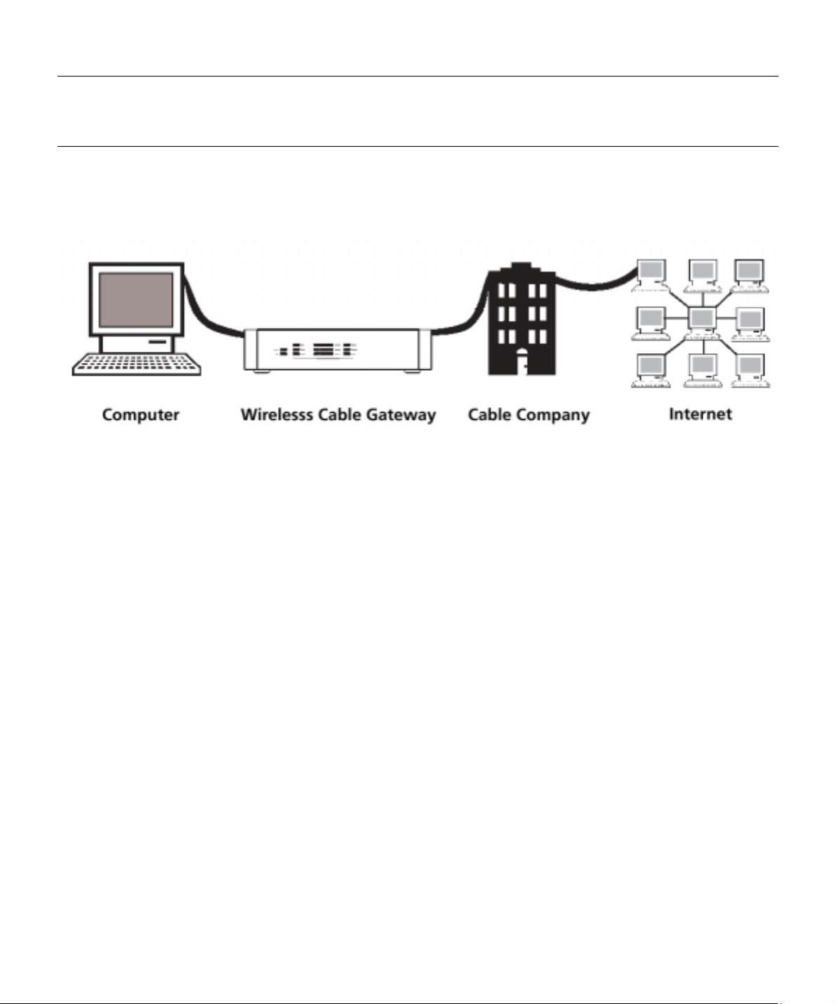
What the Wireless Cable Gateway Does
The Digital Wireless Cable Gatewa y serves as a two-way high-speed bridge between your
personal computer and a cable Internet Service Provider (ISP). It converts information that
originates from the Internet or your computer into electronic messages that can be transported
over the same wires your cable company uses to transport video signals.
What the Wireless Cable Gateway Needs to Do Its Job
• The Right Cable Company: Make sure your cable company provides da ta services that use
cable TV industry-standard EURO-DOCSIS technology.
• The Internet Service P rovi de r ( ISP) : Your cable company provides you access to an Internet
Service Prov ider (ISP). The ISP is you r ga tew ay to the Internet. It provides you with a pipeline
to access Internet content on the World Wide Web ( WWW).
Check with your cable company to make sure you have everything you need to begin; they’ll
know if you need to install special software or re-configure your computer to make your cable
Internet service work for you.
Illu strations contained in this document are for representation only.
3
Chapter 1: Connections and Setup
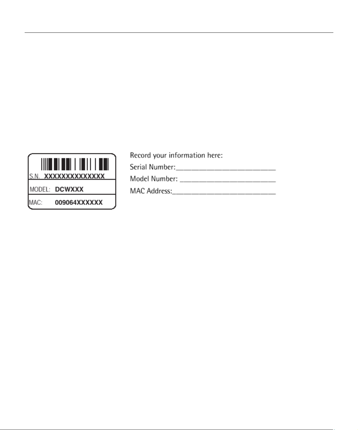
Contact Your Local Cable Company
You will ne ed to co ntac t your c able c ompa ny to estab lish a n In ternet ac coun t before y ou can use
your gateway. You should have the following information ready (which you will find on the
sticker on the gateway):
• The serial number
• The model number
• The Media Access Control (MAC) address
Please verify the following with the cable company:
• The cable service to your home supports EURO-DOCSIS-compliant two-way modem access.
• Your Internet account has been set up.
• You have a cable outlet near your PC and it is ready for cable modem service.
Note: It is important to su pply power to the modem a t all times. Keepin g you r modem plugged in
will keep it connected to the Internet. This means that it will always be ready when you are. To
disconnect your computer from the Internet, use the ON/OFF button to put the modem in
standby mode.
Important Information
Your cable company should always be consulted before installing a new cable outlet. Do not
attempt any rewiring without contacting your cable compan y first.
4

Chapter 1: Connections and Setup
System Overview
The Wireless Cable Gateway is connected between your cab le c om p any and the PCs w ithin y our
home, as pictured previously in the Wireless Cable Gateway Overview. The connection to the
cable company is made by a coaxial cable, and is referred to as the WAN (Wide Area Network)
side of your Wireless Cable Gateway. The connections to your PCs are made by your choice of
several standard home networking methods: Ethernet, USB, or 802.11b Wireless, and are
referred to as the LAN (Local Area Network) side of your Wireless Cable Gateway. Multiple PCs
can use any or all of the LAN side connections simultaneously to share your single cable
company connection, up to a maximum of 254 PCs total.
Unlike a simple hub or switch, the gateway’s setup consists of more than simply plugging
hardware together. You’ll need to configu re your netw orked P Cs to ac cep t the IP a dd ress es the
gateway assigns them (if applicable), and you will also need to configure the gateway with
settings provided by your cable company.
Illu strations contained in this document are for representation only.
5
Chapter 1: Connections and Setup
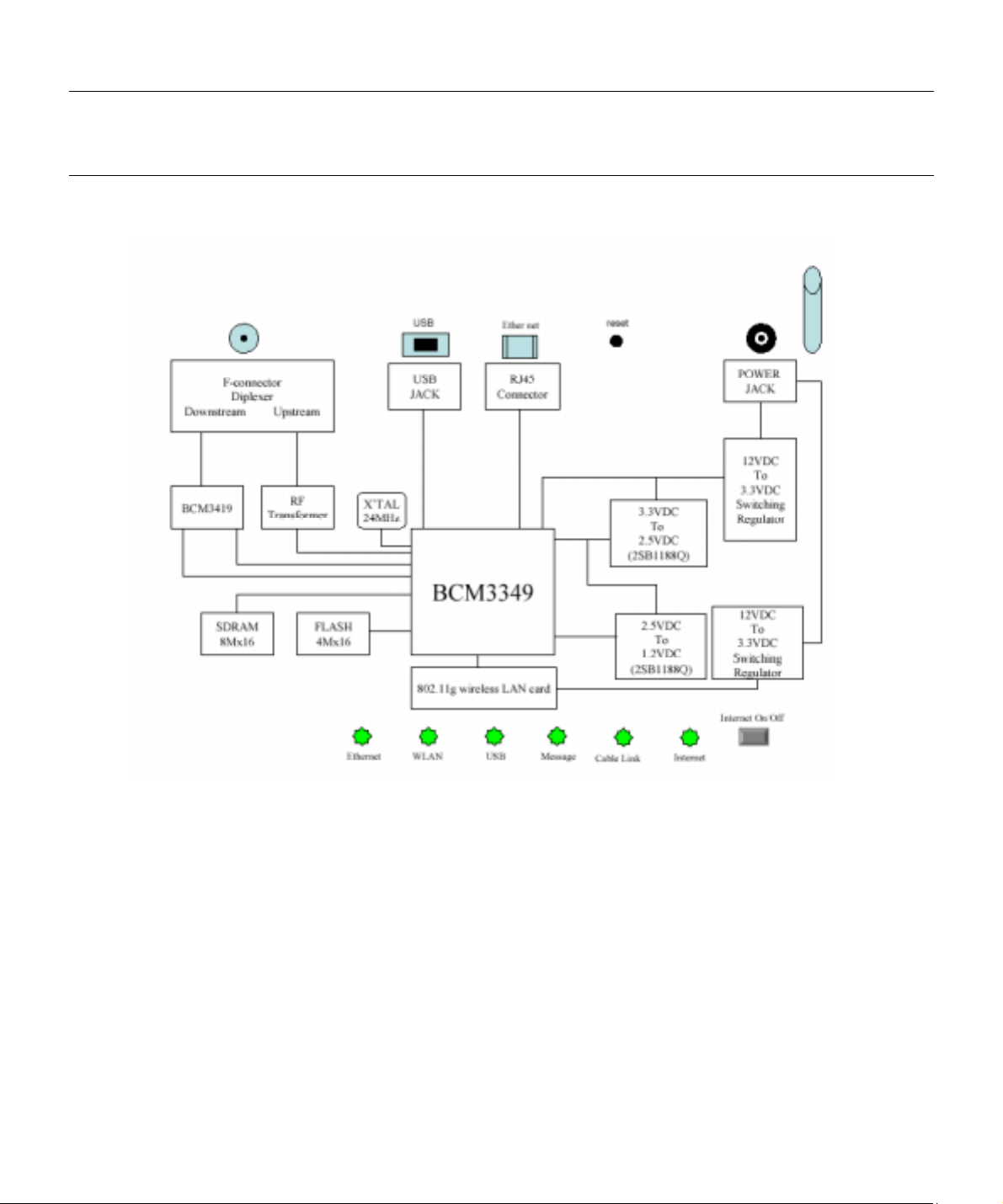
Understanding the Wireless Cable Gateway
Connect
Fig. 1
6

Chapter 1: Connections and Setup
Your PC: Installing a PC Network Card
If your PC does not already support Ethernet or USB, you must install a network interface card.
Following is an example setup procedure:
1. Install an Ethernet card on your motherboard, following the card’s directions.
2. Power up your PC and follow the Add New Hardware Wizard’s instructions to install the
driver. When asked to restart your computer at the end of the installation, click Yes.
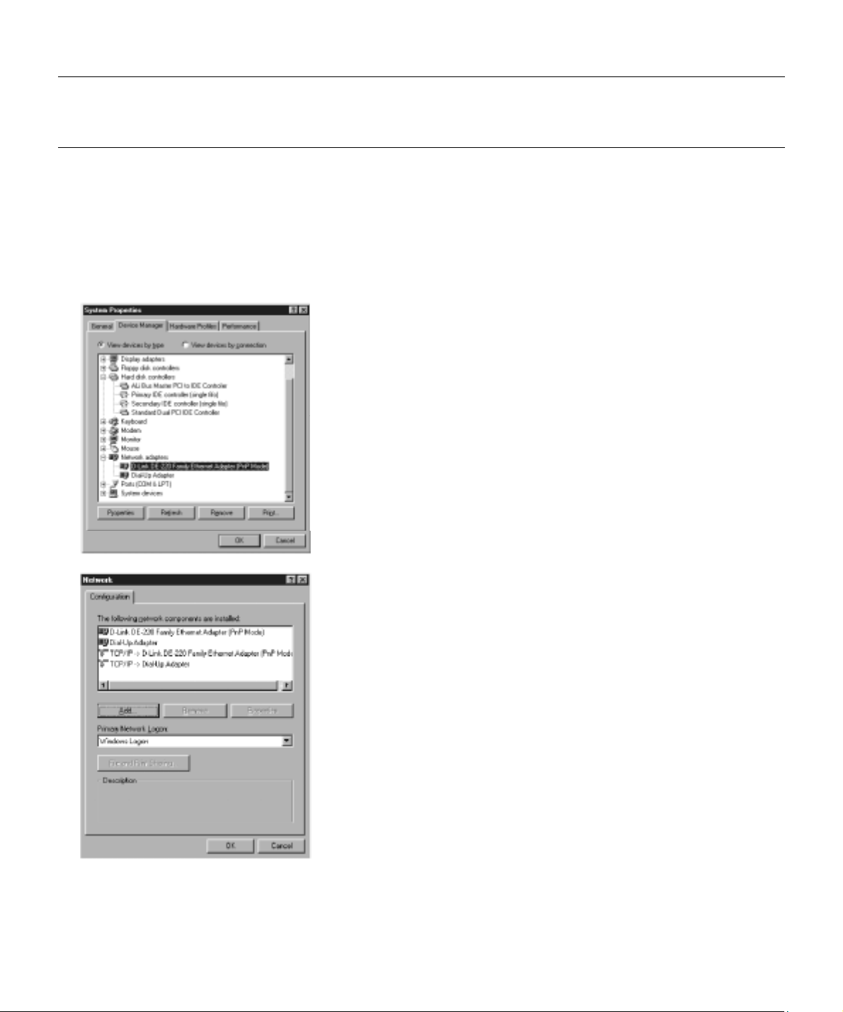
3. After re sta r tin g th e sy st em, ri gh t-c li ck M y Com pu ter on th e d es kto p , se lec t P rop er ti es, cl ic k
the Device Manager tab, and then double-click Network adapters to confirm that the
Ethernet driver is properly installed.
Illu strations contained in this document are for representation only.
7
Chapter 1: Connections and Setup
Your PC: Installing a TCP/IP Stack
Follow these instructions to install the TCP/IP protocol stack on one of your PCs only after a
network card has been successfully installed inside the PC. These instructions are for Windows
Me. For TCP/IP setup under Windows NT, 2000, and XP, refer to your Windows documentation.
1. Click the Start button . Choose Settings and then Control Panel.
2. Double-click on the Network icon to bring
up your Network window. Select the
Configuration tab.
3. Click the Add button.
4. Double-click on Protocol.
8
Fig. 2
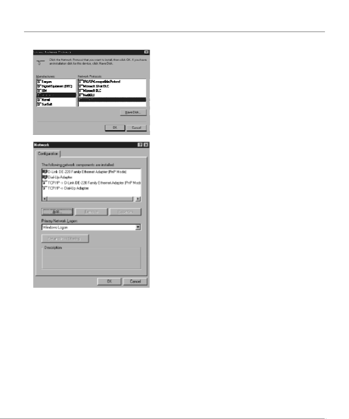
5. Highlight Microsoft under the list of
manufacturers.
6. Find and double-click TCP/IP in the list to
the right (see Figure 3).
Fig. 3
Chapter 1: Connections and Setup
7. After a few seconds, the main Network
window will appear. The TCP/IP Protocol
should now be listed.
Fig. 4
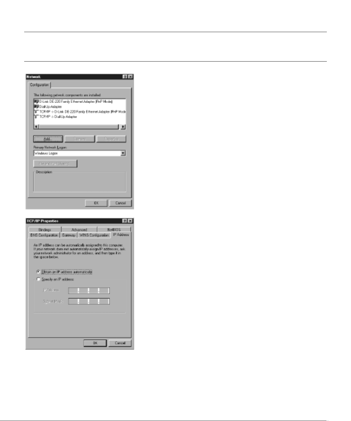
8. Click the OK button again. Windows may
ask you for the original Windows
installation disk or additional files. Supply
them by pointing to the correct file
location, e.g., D:\win9x,
Fig. 5
c:\windows\options\cabs, etc. (if “D” is the
letter of your CD-ROM drive).
9. Windows will ask you to restart the PC.
Click the Yes button.
10. The TCP /IP installation is now complete.
Illu strations contained in this document are for representation only.
9

Chapter 1: Connections and Setup
Your PC: Configuring DHCP on a TCP/IP Stack on a PC
These instructions will help you configure each of your computers to be able to communicate
with the gateway to obtain an IP (or TCP/IP) add ress automatically (called DHCP, Dynamic Host
Configuration Protocol).
Find out which operating system your computer is running by clicking the Start button and then
going to the Settings option. Then click Control Panel and double-click the Sy stem ic on. If your
Start menu doesn’t have a Settings option, you ’r e ru nning Wind ows XP . Clic k the Canc el b u tton
when done.
You may need to do this for each computer you are connecting to the gateway.
Important: Th ese instructions apply only to Windows Me, 2000, or XP machin es. For TCP/IP setup
under Windows NT, see your Windows manual. By default Windows 2000, Me, and XP have
TCP/IP installed and set to obtain an IP address automatically.
The next few pages tell you, step by step, how to configure your network settings, based on the
type of Wind ows operating sys tem y ou are usi ng. Ma ke sure that an E therne t card o r adap ter has
been successfully installed in each PC you want to configure.
10
Configuring Windows Me PCs
Chapter 1: Connections and Setup
1. Go to the Network screen by clicking the Start
button. Clic k Settings and then Control Pane l.
From there, double-click the Network icon.
2. On the Configuration tab, select the TCP/IP
line for the applicable Ethernet adapter. Do
not choose a TCP/IP entry whose name
mentions DUN, PPPoE, VPN, or AOL. If TCP/IP
appears by itself, select that line. (If there is
no TCP/IP line listed, you need to install a
TCP/IP stack). Refer to Your PC: Installing a
TCP/IP Stack. Click the Properties button.
Fig. 6
Fig. 7
3. Click the IP Ad d r e ss ta b. Se l ec t Obtain an IP
address automatically.
4. Now click the Gateway ta b to ens ur e th at th e
Installed gateway field is left blank. Click the
OK button.
5. Click the OK button again. Windows ma y a sk
you for the original Wi ndows ins talla tion disk
or additional files. Supply them by pointing
to the correct file location, e.g., D:/win9x,
c:¥windows¥optionscabs, etc. (if “D” is the
letter of your CD-ROM drive).
6. Windows may ask you to restart your PC.
Click the Yes button. If Window s does not ask
you to r e s ta r t, r e s ta rt y ou r c o m puter a ny way .
Illu strations contained in this document are for representation only.
11

Chapter 1: Connections and Setup
Configuring Windows 2000 PCs
1. G o to the N etwo rk sc r ee n by cl ic k i ng the S ta r t button . Cl i c k S etti n gs a nd th en C on tr ol P a ne l .
From there, double-click the Network and Dial-up Connections icon.
2. Select the Local Area Connection icon for the applicable Ethernet adapter (it’s usually the
first Local Area Connection listed). Double-c lick the Local Area Connection. Click the
Properties button.
3. Select Internet Protocol (TCP/IP), and click the Properties button.
4. Select Ob tain an IP address automati cally. Once the new window appears, click the OK
button. Click the OK button again to complete the PC configuration.
5. Restart your computer.
Configuring Windows XP PCs
The following instruc tions assu me y ou are runni ng Window s XP w ith the defaul t interface. If you
are using the Classic interfac e (where the ico ns and menus look like previous Windows vers ions),
please follow the instructions for Windows 2000.
1. Go to the Network screen by clicking the Start button and then Control Panel. From there,
double-click the Network Internet Connections icon and then the Network Connections icon.
2. Select the Local A rea C onn ec tion ico n for the app lic able E therne t ad apter ( i t’s usu ally the fi rs t
Local Area Connection listed). Double-click the Local Area Connection. Click the Properties
button.
3. Select Internet Protocol (TCP/IP), and click the Properties button.
4. Select Ob tain an IP address automati cally. Once the new window appears, click the OK
button. Click the OK button again (or the Close button if any settings were changed) to
12

Chapter 1: Connections and Setup
complete the PC configuration.
5. Restart your computer.
Connecting Your Devices
1. Before you begin, make su re that all of your hardw are is powered off, including the gateway ,
PCs, hubs, and switches.
2. Connect one end of an Ethernet cable to one of the LAN ports (labeled 1, 2, 3, or 4) on the back
of the gateway and the other end to a standard port on a network device, e.g., a PC, print
server, hub, or switch. Repeat the above step to connect more PCs or network devices to the
gateway.
3. Connect the coaxial cable from the wall to the CABLE jack on the back of the gateway.
4. Connect the power supply cable to the Power ja c k on the back of the gateway , then plug the
supplied power cable into an AC power outlet.
Activating the Wireless Cable Gateway
Initialization
1. Connect the power cable to the back of the gateway. For the first few seconds of operation,
multiple LEDs will flash in unison while the gateway performs self-test diagnostics.
The Cable Modem section of the gateway proceeds with EURO-DOCSIS initialization. In this
process, the CM performs the following sequence of steps. For a newly-installed gateway, this
can take as much as 2 0 m inutes to comp lete.
• Tuning - searching for a downstream EURO-DOCSIS CM signal
• Ranging - establishing 2-way communication with the cable company
• Connecting - obtaining the CM IP Address (for IP Stack 1)
Illu strations contained in this document are for representation only.
13

Chapter 1: Connections and Setup
• Configuring - downloading and applying the cable company CM configuration file
• Registering - establishing Internet access with the cable company
During this process, the LED indicators on the front of the unit indicate progress.
• DS – Flashing indicates Tuning; lit solid indicates Tuning step completed successfully.
• US – Flashing indicates Ranging; lit solid indicates Ranging step completed successfully.
• Online – Flashing indicates Connecting, Configuring, Registering in progress; lit solid
indicates these steps completed successfully.
When the Online LED is lit solid, all gateway initialization and startup steps have been
completed successfully, and the gateway should be capable of providing connectivity
between your PCs on the gateway LAN-side and your cable operator on the gateway
WAN-side.
Mandatory User Configuration
This feature a l lows you to c onfi g ure the ga tewa y to fu n ctio n in yo u r network a n d g a in ac cess to
the Internet through your c able company. Your ISP may require the use of a Host Name and
Domain Name. You w ill need to get the setup information from your ISP. If you do not have this
information, please contact your ISP before proceeding.
The instructions from your ISP will tell you how to set up your PC for Internet access. Also, you
must disable any Internet log-on software (such as Ivasion Winpoet or Enternet 300) and any
rewall software (such as ZoneAlarm and Watchdog) on all of your PCs.
To set up your gateway for internet access, you will use its built-in web pages feature. The
gateway includes a built-in HTTP server which can deliver many web-style pages of information
with which you can observe your current gateway settings and make changes.
14
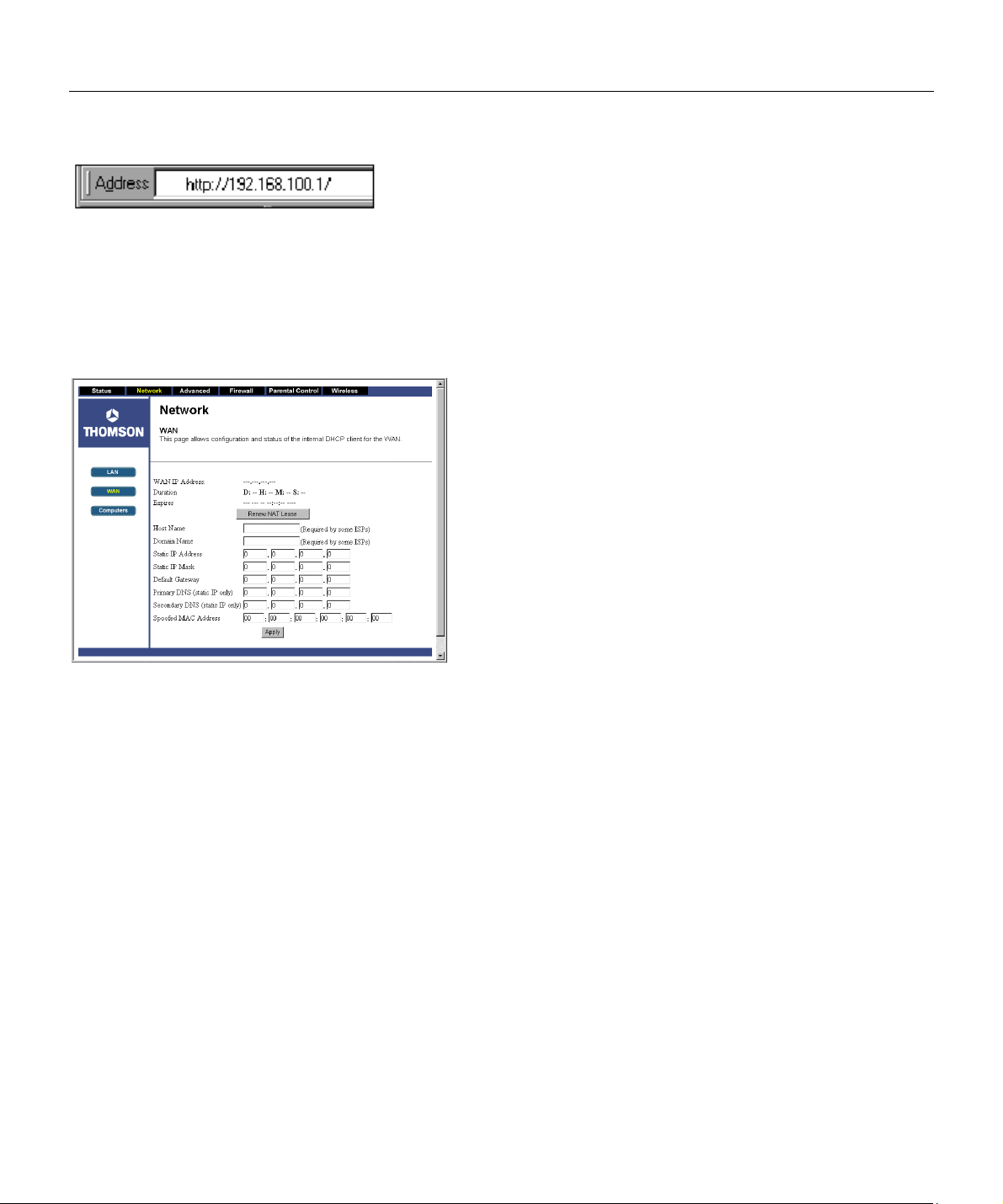
Fig. 8
Chapter 1: Connections and Setup
1. Open your web browser. (It’s all right if you
get an error message at this point. Continue
following these directions). Enter
http://192.168.100.1 in the browser’s
Address field if your gateway is in the CM
Mode, or http://192.168.0.1 if it is in the RG
or CH Mode. Press the Enter key.
2. An Enter Network Password window appears
(for Windows XP us ers, the screen may look
different). Leave the User Name field empty,
and enter admin in lowercase letters in the
Password field (admin is the default
password). Then, click the OK button.
Fig.9
3. This step is not required with most installations. However, based on setup instructions from
your ca ble co mpa ny , you may need to e nter the f oll ow ing i nform a tion. To e nter it, nav iga te to
the Network – WAN gateway web page by clicking Network at the top of the page, then click
WAN (on the left side of the page). Click the Apply button to save your settings.
Host Name and Domain Name: These fields allow you to provide a host name and domain
name for the gatew ay. These fields a re usuall y left bla nk. If requ ested by your cable comp any ,
complete these two fields.
Static IP Address and IP Mask: If your cable company says that you are connected through a
static or fixed IP address, you should enter the field of Default Gateway, Prim ary DNS and/or
Secondary DNS also.
Spoofed MAC Address: You can give a spoofed MAC Address to hide your gateway’s real MAC
address. Howev er, this is NOT recomme nded, as this c ould caus e an address c onflic t, causing
Illu strations contained in this document are for representation only.
15
Chapter 1: Connections and Setup
your connection to the network to be rejected.
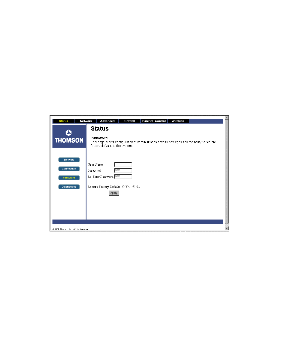
4. The gateway provides a Status Password webpage where you can change the web page’s
access password and res tore fac tory default of the gateway. Also, you can c hange the def au lt
“admin” password to the desired password. Click the Apply button to save your settings.
IMPORTANT: If you have previously enabled any Internet-Sharing Proxy server software on any of
your PCs, disable it.
Fig. 10
Some examples of Internet-sharing software are Internet LanBridge, Wingate, ICS, and Sygate. To
disable your Internet-sharing software:
• If you are running Netscape Navigator: Click Edit >> Preference >> Advanced >> Proxies >,
and click Direct Connection to the Internet.
• If you a re running Internet Explorer v5 or better, click Start >> Settings >> Control P anel >>
Internet Options >> Connections >> LAN Settings. Remove the checks from a ll three boxes .
Click OK to continue.
16
Chapter 1: Connections and Setup
Overview
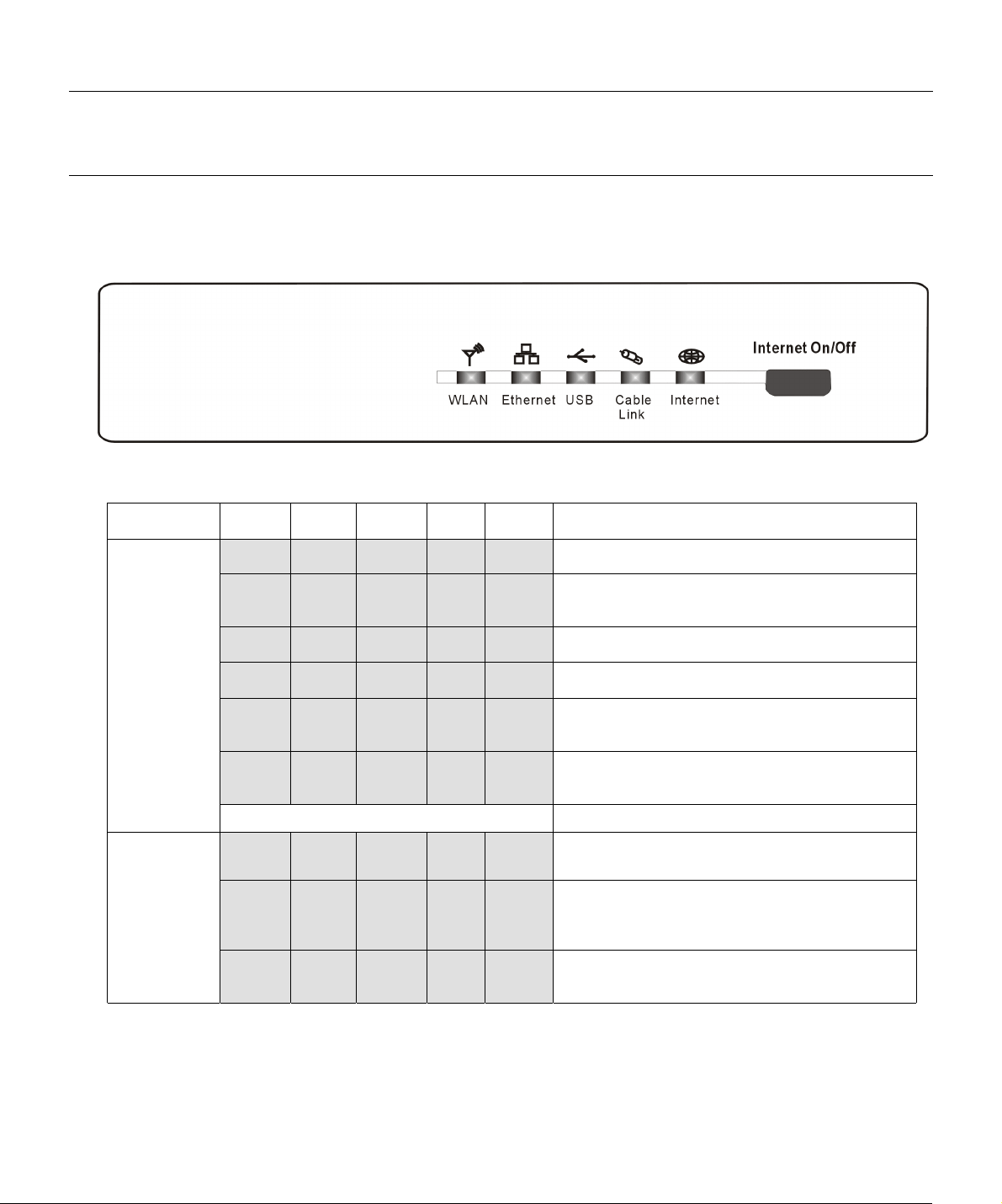
Front Panel
The following illustration shows the front panel of the Gateway machine:
The LEDs on the front panel are described in the table below (from left to right):
TCW710 WLAN Ethernet USB
OFF OFF OFF OFF
OFF OFF OFF
OFF OFF OFF
Start-up
Operation
Normal
Operation
OFF OFF
OFF
FLASH FLASH FLASH FLASH FLASH
FLASH FLASH FLASH FLASH
Enter Normal Operation Mode Registration complete
X X X X
X X X
X X
FLASH FLASH FLASH
OFF
ON
Cable
Link
FLASH FLASH
FLASH FLASH
OFF
FLASH
Internet Description
FLASH
OFF
ON
X
ON
X X
Tuning (Searching downstream signal)
Ranging - Awaiting Response
(DS carrier acquire, ranging in process but RNG-RSP
has not been detected)
Any RNG-RSP detected
(Normalizing power level and timing offset)
Connecting
(Ranging complete, DHCP in progress)
Configuring
(DHCP complete, configuration file download in
process)
Registering and Baseline Privacy Initializing
(configuration file download complete, initialize BPI if
BPI is ON, registration in process)
Internet ON-OFF switch off
Internet ON-OFF switch on
NO Cable Link
Cable BSS/OSS has set the CM into de-activated
state
CM is registered
NO USB carrier present
USB carrier present, no traffic
Illu strations contained in this document are for representation only.
17

Chapter 1: Connections and Setup
SW Download
Operation
No service
Operation
Press Button
Internet
On/Off
Button
OFF
FLASH
X
ON
OFF
FLASH
ON
FLASH FLASH FLASH FLASH FLASH
X X X Wink X
Three seconds ON followed by a flash OFF
X X X X
From Right to Left
On Internet ON-OFF switch on.
X X X
Off Internet ON-OFF switch off.
NO Ether carrier present
Ether TX/RX traffic
Ether carrier present, no traffic
No 802.11g installed or wireless is disabled from
WEB
Wireless TX/RX traffic
802.11g is functional
A software download and while updating the FLASH
memory
NACO =OFF
BPI unauthorize (when BPI is ON)
18

Rear Panel
9-12VDC: Power connector
Chapter 1: Connections and Setup
Reset Reset-to-Default push button
Ethernet: Ethernet 10/100BaseT RJ-45 connector
USB: USB Connector
CABLE: F-Connector
Illu strations contained in this document are for representation only.
19

Chapter 2: Networking
Chapter 2: Networking
Communications
Data communication involves the flow of packets of data from one device to another. These
devices include personal computers, Ethernet and USB hubs, cable modems, digital routers and
switches, and highly integrated devices that combine functions, like the Wireless Cable Gateway.
The g ate w ay inte gr a tes the fu nc tio na li ty o fte n f ou nd in tw o sep ar at e d evi ces i nto on e. I t’ s bo th a
cable modem and an intelligent wireless gateway networking device that can provide a host of
networking features, such as NAT and firewall. Figure 2 illustrates this concept, with the cable
modem (CM) functionality on the left, and networking functionality on the right. In this figure,
the numbered arrows represent communication based on source and destination, as follows:
Type of Communication
1. Communication between the Internet and your PCs
Example: The packets created by your request for a page stored at a web site, and the
contents of that page sent to your PC.
2. Communication between your cable company and the cable modem side
Example: When your cable m odem starts up, it must initialize with the cable company, which
requires the cable company to communicate directly with the cable modem itself.
3. Communication between your PCs and the networking side
20

Chapter 2: Networking
Fig.11
Example: The Wireless Cable Gateway offers a number of bu ilt-in web pages, which y ou can
use to configure its networking side; w hen you com municate w ith the networking side, y our
communication is following this path.
Each packet on the Internet addressed to a PC in your home travels from the Internet downstream on the ca ble c omp any ’s sy stem to the WAN si de of you r Wire less Ca bl e Gatew ay . T here i t
enters the Cable Modem section, which insp ects the packet, and, based on the resu lts, proceeds
to either forward or block the packet from proceeding on to the Networking section. Similarly,
the Networki ng section then decides w hether to f orward or b lock the packet from pr oceeding o n
to your PC. Communication from your home device to an Internet device works similarly, but in
reverse, with the packet traveling up stream on the cable system.
Cable Modem (CM) Section
The cable modem (or CM) section of your gateway uses EURO-DOCSIS Standard cable modem
technology. EURO-DOCSIS specifies that TCP/IP over Ethernet style data communication be used
between the WAN interface of your cable modem and your cable company.
A EURO-DOCSIS modem , w hen connec ted to a Cable System equipped to supp or t such modems ,
performs a fully au tomated initialization process that requires no user intervention. Part of this
Illu strations contained in this document are for representation only.
21

Chapter 2: Networking
initialization configures the cable modem with a CM IP (Cable Modem Internet Protocol) address,
as shown in Figure 3, so the cable company can communicate directly with the CM itself.
Networking Section
The Networking section of your gateway also uses TCP/IP (Transmission Control Protocol/
Internet Protocol) for the PCs you connected on the LAN side. TCP/IP is a networking protocol
that provides commu nication across interconnected networks, between c ompu ters with div erse
hardware architectures and various operating systems.
TCP/IP requires that each communicating device be configured with one or more TCP/IP stacks,
as illustrated by Figure 4. On a PC, y ou often use software that came with the PC or its network
interface (if you purchased a network interface card separately) to perform this configuration. To
comm un ica te w ith the In tern et, th e s tack mu st a lso be a ss ign ed a n IP ( Inter ne t Pr otoc ol ) a ddre ss.
192.168.100.1 is an example of an IP address. A TCP/IP stack can be configured to get this IP
address by various m eans, inc ludi ng a DHCP serv er, by y ou directly enteri ng it, or som etim es by
a PC generating one of its own.
Etherne t requires that each T CP/IP s tack on the Wir eless Cab le Gate way also hav e associ ated with
it an Ethernet MAC (Media Access Control) address. MAC addresses are permanently fixed into
network devices at the time of their manufacture. 00:90:64:12:B1:91 is an example of a MAC
address.
Data packets enter and exit a device through one of its network interfaces. The gateway offers
Ethernet, USB, and 802.11b/g wireless network interfaces on the LAN side and the EURO-DOCSIS
network interface on the WAN side.
When a pac ket ente rs a netw ork i nter fac e, i t is of fere d to a ll the TC P/I P stac ks a sso cia ted w ith the
device side from which it entered. But only one stack can accept it — a stack whose configured
Ethernet address matches the Ethernet destination address inside the packet. Furthermore, at a
packet’s final destination, its destination IP address must also match the IP address of the stack.
Each packet that enters a device contains source MAC and IP addresses telling w here it came
from, and destination MAC and IP addresses telling where it is going to. In addition, the packet
contains all or part of a message destined for some application that is running on the destination
22

Chapter 2: Networking
device. IRC used in an Internet instant messaging program, HTTP used by a web browser, and
FTP used by a file transfer program are all examples of applications. Inside the packet, these
applications are designated by their port number. Port 80, the standard HTTP port, is an example
of a port number.
The Networking section of the router performs many elegant functions by recognizing different
packet types based upon their contents, such as source and destination MAC address, IP address,
and ports.
Three Networki ng Modes
Your gateway can be configured to provide connectivity between your cable company and your
home LAN in any one of three Networking Modes: CM, RG, and CH. This mode setting is under
the control of your cable company, who can select the mode to match the level of home
networking suppo rt for w hich y ou have subsc ribed. A ll units sh ip from the factory set for the RG
mode, but a configuration file which the cable company sends the cable modem section during
its initialization can change it.
Cable Modem (CM) Mode
Fig. 12
Illu strations contained in this document are for representation only.
23

Chapter 2: Networking
Fig. 13
CM (Cable Modem) Mode prov ides basic hom e networki ng. In this mod e, two IP s tacks are active:
• IP Sta ck 1 - fo r us e by the c abl e co mpa ny to co mmu nic ate w i th the cab le m ode m sec ti on o nly .
This stack receives its IP address from the cable company during CM initialization. It uses the
MAC address printed on the label attached to the Wireless Cable gateway.
• IP Stack 2 - for use by you, the end user, to communicate with the cable modem and
Networking sections, to access the internal web page diagnostics and configuration. This
stack uses a fixed IP address: 192.168.100.1. It uses a MAC address of MAC label + 1 (the
MAC label is found on the bottom of the unit). E.g., if the MAC address is 00:90:64:12:B:91
this MAC address would be 00:90:64:12:B1:92.
With CM Mode, you r cable compa ny must prov ide one IP addr ess for the CM section, plu s one for
each PC you connect from their pool of available addresses. Your cable company may have you
or your installer manually e nter these assigned addresse s into your PC, or use a DHCP Server to
comm un ica te th em to y ou r PC s, or us e a m eth od tha t inv olv es you en teri ng hos t nam es in to y our
PCs.
24

Chapter 2: Networking
Note that i n CM Mode, packets passing to the Internet to/from your PCs do not travel through
any of the IP stacks; instead they are directly bridged between the WAN and LAN sides.
Residential Gateway (RG) Mode
Fig. 14
Fig. 15
Illu strations contained in this document are for representation only.
25

Chapter 2: Networking
RG (Residential Gateway) Mode provides basic home networking plus NAT (Network Address
Translation). In this mode, three IP stacks are active:
• IP S tac k 1 - for use by the c ab le c omp any to com mu nic ate w i th th e C abl e Mod em sec tio n o nly .
This stack receives its IP address from the cable company during CM initialization. It uses the
MAC address printed on the label attached to the Wireless Cable Gateway.
• IP Stack 3 - for u se by you to rem otely ( i.e. fr om somew her e on the WA N si de, su ch as at y our
remote workplace) communicate with the Cable Modem and Networking sections, to
remotely acc ess the i nter nal web page diagnos tics a nd configuration . T his s tac k is al so u se d
by y our cab le c om pa ny to d el iv er p ac ke ts b et we en th e I nte rn et and th e ga tew ay ’ s ne tw or kin g
section so they can be routed to/from your PCs. This stack requires an IP address assigned by
the cabl e com pany fro m their po ol o f av ailabl e add ress es. Y ou r cab le c ompa ny m ay ha ve you
or your installer manually enter as s i g ned a d d r esses into y our gatew ay, or use a DHCP Server
to communic ate them, or use a method that involves you entering host names. This stack
uses a MAC address o f MAC label + 2 (the MAC lab el is found o n the bottom of the unit). E. g.,
if the MAC address is 00:90:64:12:B1:91, this MAC address would be 00:90:64:12:B1:93.
• IP Stack 5 - for use by you to locally (i.e. from somewhere on the LAN side in your home)
comm unicate with the Cable Modem and Networking sections, to access the inte rna l web
page diagnostics and configuration. This stack is also used by the gateway’s networking
section to route packets between the gateway’s Netw orking section and you r PCs. This stack
uses a fixed IP address: 192.168.0.1. It uses a MAC address of MAC label + 4 (the MAC label
is found on the bottom of the unit). E.g., if the MAC address is 00:90:64:12:B1:91, this MAC
address would be 00:90:64:12:B1:95.
With RG M ode, y ou r cab le co mpa ny m us t prov ide one IP ad dr ess f or the CM sec tion, plus one f or
the Networking section, from their pool of available addresses. With RG Mode, each PC you
connect gets an IP address from a DHCP Server that is part of the Networking section of the
gateway.
26

CableHome (CH) Mode
Chapter 2: Networking
Fig. 16
CH (CableHome) Mode pr ovides all the func tionality of RG m ode and adds the ability of the cable
company to control the home networking configuration of y ou r Wireless Cabl e Gateway for you,
so you don’t need to perform the configuration yourself. In this mode, four IP stacks are active:
• IP S tac k 1 - for use by the c ab le c omp any to com mu nic ate w i th th e C abl e Mod em sec tio n o nly .
This stack receives its IP address from the cable company during CM initialization. It uses the
MAC address printed on the label attached to the Wireless Cable Gateway.
• IP Stack 3 - for use by your cable company to communicate with the Networking section to
help you configure and manage your home networking. This stack requires an IP address
assigned by the cable co mpany from their pool of available addresses. Your cable company
may have you or your installer manually enter assigned addresses into your gateway, or use a
DHCP Server to communic ate them, or use a method that involves y ou entering host names.
This stack us es a M AC addr ess of MA C labe l + 2 ( the M AC lab el is fou nd on the bottom of the
unit). E.g., if the MAC address is 00:90:64:12: B1:91, this MAC address wou ld be 00:90:64:12:
B1:93.
Illu strations contained in this document are for representation only.
27

Chapter 2: Networking
• IP Stack 4 - for u se by you to rem otely ( i.e. fr om somew her e on the WA N si de, su ch as at y our
remote workplace) communicate with the Cable Modem and Networking sections, to
remotely acc ess the i nter nal web page diagnos tics a nd configuration . T his s tac k is al so u se d
by your cable company to deliver pa ckets between the Internet and the Wireless Cable
Gateway ’s Ne two rk in g se cti o n s o th ey ca n b e r ou ted to /f rom y ou r PC s. T hi s s ta ck re qu ire s a n
IP address assigned by the cable c ompa ny fro m their pool of av ailab le ad dr esse s. You r cab le
company may have you or your installer manually enter these assigned addresses into your
gateway, or use a DHCP Server to communicate them, or use a method that involves you
entering host names. This stack uses a M AC address of MAC lab el + 3 (the MAC l abel is found
on the bottom of the unit). E.g., if the MAC address is 00:90:64:12:B1:91, this MAC address
would be 00:90: 64:12:B1:94.
• IP Stack 5 - for use by you to locally (i.e. from somewhere on the LAN side in your home)
comm unicate with the Cable Modem and Networking sections, to access the inte rna l web
page diagnostics and configuration. This stack is also used by the Wireless Cable Gateway
Networking section to route packets between the Wireless Cable Gateway’s Networking
section and your PCs. This stack uses a fix ed IP address: 192.168.0 .1. It uses a MAC ad dress
of MAC label+ 4 ( the MAC label is f ound on the b ottom of the unit). E.g. , if the MAC addr ess is
00:90:64:12:B1:91, this MAC address would be 00:90:64:12:B1:95.
With CH Mode, your cable company must provide one IP address for the CM section, plus two for
the Networking section, from their pool of available addresses. Each PC you connect gets an IP
address from a DHCP Server that is part of the Netw orking section of the gateway.
USB MAC Address
USB allows a single PC to be connected directly via your Wireless Cable Gateway USB port. Other
PCs can, of course, be connected to your other networking interfaces: wireless, HPNA, and
Ethernet. If you have a PC connected by USB, the following information is helpful.
The PCs you have connected by 802.11b/g Wireless, and Ethernet technologies associated with
your gateway all send and receive packets that contain the Ethernet-style MAC address
associated with that network interface. USB technology, however, uses a different addressing
approach. In this situation, your gateway modi es the packets going to and from your
28

Chapter 2: Networking
USB-connected PC to make them look Ethernet-style when passed between you and your cable
company. To do this, the gateway must effectively “loan” an Ethernet-style address for u se in all
these pac kets. For thi s purpose, the gatew ay uses a M AC address of MAC label + 5 (the MAC la bel
is found on the bottom of the unit). E.g., if the MAC address is 00:90:64:12:B1:91, this MAC
address would be 00: 90:64:12:B1:96.
MAC and IP Addresses Summary
This table summarizes all the MAC and IP addresses that may be associated with the TCP/IP
commu nicati on s tack s and USB ha ndl ing in y our Wir ele ss Ca ble G ate w ay. The o nes actu ally us ed
depend upon your gateway Operating Mode, as explained above. At minimum, your cable
company will need to know the MAC address associated with IP Stack 1, which is the MAC
address shown on the modem label.
Stack Name Purpose - Mode MAC Address IP Address
IP Stack 1
IP Stack 2
IP Stack 3
IP Stack 4
IP Stack 5
---
WAN data access -
local management -
CM WAN access - all Modes
local management - CM Mode
only CM label + 1 fixed at 192.168.100.1
CableHome remote management CH Mode only
end-user remote management,
LAN WAN access - RG Mode only
CH Mode only
RG, CH Modes only
LAN gateway
MAC and IP Addresses
per label on CM assigned by cable company during
initialization
CM label + 2
CM label + 3
CM label + 4 fixed at 192.168.0.1
CM label + 5
assigned by cable company
assigned by cable company
Illu strations contained in this document are for representation only.
29

Chapter 3: Advanced Configuration
Chapter 3: Advanced Configuration
Advanced User Configuration
The Wireless Cable Gateway offers local management capability through a built in HTTP server
and a number of diagnostic and configuration web pages. These pages are available from
http://192.168.0.1 in RG and CH modes, and http://192.168.100.1 in CM Mode. Not all pages
are available in some modes.
Some information on two of the following web pages MUST BE configured, as explained in
Mandatory User Configuration.
In addition, more configuration and diagnostics are possible through the following additional
web pages, most of which are aimed at controlling the advanced networking functions of the
gateway.
To navigate between pages, use the hyperlinks on the top of the page, and the side bar on the
left side of the page. For easy navigation, the pages are organized in groups, with group names
at the top of the pages. Indiv idual page names wi thin each group are pr ovided i n the sidebar. T o
navi g a te to a pa g e , c l ic k th e g r oup hy pe r li n k a t the to p , th en t he pa g e hyperl i n k o n th e si d ebar.
Your cable company may not support the repor ting of some items of i nformation listed on your
gateway’s internal w eb pages. In such cases, the information fi eld appears bla nk. This is norm al.
In th e CM Mode , the sim p l e st confi g ura tion mode o f the g ateway, or in the CH Mo de, wher e you
have subsc ribed to an ou tside serv ice (y our cable c ompany or ano ther par ty) to rem otely manage
your home ne twork conf igura tion, y ou will se e only the Statu s and Wir eless w eb page hy perlinks
in the sidebar, indicating only these page groups are available.
In the RG M ode, the mode w here you manage y our hom e netw ork configu ration, y ou w ill see web
page hyperlinks to all five page groups: Status, Basic, Advanced, Firewall, and Wireless.
The following section explains all of the available pages for all of the modes.
30

Chapter 3: Advanced Configuration
Note: Your gateway c omplies with EURO-DOCSIS standards regarding software upgrades.
EURO-DOCSIS requires that an y software upgrade to a device that is conn ected to a cable system,
like your gateway, must be "pushed" to the gateway by the cable operator. Also, the features of
the gateway, and the embedded web pages that control those features, can vary by software
version. Therefore, yo u may find that you r gatew ay's web pages an d featu res vary sligh tly from
those shown here. This is normal, and is the result of a software upgrade your cable operator
has made to your gateway.
Illu strations contained in this document are for representation only.
31

Chapter 3: Advanced Configuration
Status Web Page Group
Software Web Page
The Information section of this page provides hardware and softw a re information about your
gateway that may be useful to your cable company. You can view your operating software version
but not change it. This is because your gateway adheres to the EURO-DOCSIS Ca ble Mo dem
standard, which requ ires tha t your cable com pany perf orm any softw are upgrade of the gateway
from the gateway WAN side.
The Status section of this page shows how long your gateway has operated since last being
powered up, and some key information the Cable Modem section received during the
initialization process with your ca ble company. If Network Access shows “Allowed,” then your
cable company has configured your gateway to have Internet connectivity. If Network Access
shows otherwise, you may not have Internet access, and should contact your cable company to
resolve this.
Fig. 17
32

Chapter 3: Advanced Configuration
Connection Web Page
This page reports diagnostic information about the initialization and operating status of your
gateway that can be useful at the time of installation. It can also be useful to your cable
company’s support technician if you’re having problems.
Fig.18
Illu strations contained in this document are for representation only.
33

Chapter 3: Advanced Configuration
Password Web Page
This pag e is u sed to se t a p assw ord tha t enab les you to ac cess all the gatew ay inte rnal we b pag es.
The password can be a maximum of 8 characters and is case sensitive. In addition, this page can
be used to restore the gateway to its original factory settings. Use this with caution, as all the
settings you have made will be lost. To perform this reset, set Restore Factory Defaults to YES
and click Apply. This has the same effect as a factory reset using the rear panel reset switch,
where you hold in the switch for 15 seconds, then release.
34
Fig. 19

Chapter 3: Advanced Configuration
Diag nostics Web P age
This page verifies you have IP connectivity from your gateway to other IP addresses on the LAN
side, such as when you want to confirm you have successfully configured one of your PCs for
TCP/IP operation.
When you ping an Internet device, you send a packet to its TCP/IP stack, and i t sends one back to
you rs . E n te r the IP a d d r e ss you w an t to pi n g, the n c l ick S ta r t Tes t. Wai t a f ew sec o n ds , th e n c l ick
your web browser’s refresh bu tton. Success repor ted in the Results box mea ns IP connec tiv ity is
working from your CM TCP/IP stack to the target’s stack.
Note: Firewalls may cause pings to fail but still provide you TCP/IP access to selected devic es
behind them. Keep th is in mind when pin ging a device that may be b ehind a firewall. Ping is most
useful to verify connectivity with PCs you know have no firewall, such as your own PCs on your
LAN side.
Fig.20
Illu strations contained in this document are for representation only.
35

Chapter 3: Advanced Configuration
Network Web Page Group
WAN Web Page
This page gives you the ability to enter some data your cable company may require, as explained
before in Mandatory User Configuration. In addition, it enables you to view your WAN side IP
address and lease information.
Your gateway can provide NAT/PAT (Network and Port Address Translation) as an element of
security to p reve nt others from r eaching you r PCs when n ot au th ori z ed. T o accompli sh th is, the
gateway watches packets you send from your PC to Internet sites. Each time you send to a site
(destination IP address) and application at that site (port), it translates your PC’s original IP and
sour ce por t to n ew one s, and ad ds a r ow to i ts Con nec ti on Ta bl e ma in ta in ed i nte rn al ly . ( Not e th e
different meaning of ‘connection’ here to describe an IP connection versus a physical cabling
connection). If and when that site/application replies, it looks up the connection and reverses the
IP/port process to direct the response to your PC.
The Conn ection T able mana ges itse lf, but y ou can als o force this tabl e to be cl eared ma nually . To
do this, click the Renew NAT Lease button.
Fig. 21
You can enter a spoofed MAC address that causes your gateway networking stack to use that
MAC address when communicating instead of the usual WAN MAC address (CM label + 2, as
36

Chapter 3: Advanced Configuration
explained in Chapter 2). Enter the desired MAC address and click Apply.
Caution: If you enter a MAC address in use by another party, it can cause an address conflict on
the network that could affect both you and that party.
LAN and Computers Web Pages
These pages give you the ability to activate and deactivate the DHCP server function of your
gateway, and, if the DHCP server is activated, to see DHCP leases it has provided.
With th is fu nc ti o n a c tiv a te d, y ou r c ab l e co mp a ny ’ s D HCP s er v er p r ov i des o ne I P add r es s f o r y ou r
gateway, and your ga tew ay ’s DHCP server provides IP addr esses, s tarting at the address you se t
in IP Address on the LAN page, to your PCs. A DHCP server leases an IP address with an
expiration time.
To change the lowest IP address that your gateway will issue to your PCs, enter it into the IP
Address box and then click Apply.
To set the maximum number of PCs to which the gateway will issue IP addresses, enter it in the
Number of CPEs box and then click Apply. (CPE is another term sometimes used for PC.)
The Computers w eb page section shows leases the gateway DHCP server has mad e, including the
IP and MAC addresses of each PC’s TCP/IP stack. Since MAC addresses are unique and
perm an en tly fi xed i nto ha rdwar e, y ou c an i de nti fy an y P C li ste d by it s M AC a dd re ss. T he g ate w ay
provides leas es f or 7 d ays, and has an autom a tic r en ew al m ec ha nis m tha t will ke ep extending a
lease as long as the associated PC remains active. If your PC is set to “obtain an IP address
automatically,” it is set to perform DHCP each time it is rebooted.
You can cancel an IP address lease by selecting it in the DHCP Client Lease Info list and then
clicking the Force Available button. If you do this, you may have to perform a DHCP Renew on
that PC, so it can obtain a new lease.
Illu strations contained in this document are for representation only.
37

Chapter 3: Advanced Configuration
Fig. 22
38
Fig. 23

Chapter 3: Advanced Configuration
Advanced Web Page Group
Options Web Page
This page allows you to enable/disable some features of the Wireless Cable Gateway. Check WAN
Blocking and then click Apply to prevent others on the WAN side from being able to ping your
gateway. With WAN Blocking on, your gateway will not respond to pings it receives, effectively
“hiding” your gateway.
Check Ipsec Pass Through and then click Apply to enable IpSec type packets to pass WAN <=>
LAN. IpSec (IP Security) is a security mechanism used in Virtual Private Networks (VPNs). E.g.,
your employer may offer VPN connectivity to your office network to provide security.
Check PPTP Pass Through and then click Apply to enable PPTP type packets to pass WAN <=> LAN.
PPTP (Point to Point Tunneling Protocol) is another mechanism sometimes used in VPNs. Check
Remote Config Management and then click Apply to make the configuration web pages in y ou r
gateway accessible from the WAN side. Then you could, for example, access your home gateway
configuration from your workplace, if that location also had Internet connectivity. Page access is
limited to only those who know the gateway access password you set using the Status...Passw ord
web page.
Fig. 24
Illu strations contained in this document are for representation only.
39

Chapter 3: Advanced Configuration
This function works o nly if y our gatew ay is in th e RG m ode. When accessi ng you r gatew ay from a
remote location, you must use HTTP port 8080 and your IP Stack 3 address. This is the "WAN IP
address" that appears at the Network...WAN page. For example, if this IP address were
157.254.5.7, you wou ld navigate to http://157.254.5.7:8080 to reach your gateway from a
remote location.
Check Multicast Enable and then click Apply to enable multicast traffic to pass WAN <=> LAN.
You may need to enable this to see some types of broadcast streaming and content on the
Internet, such as webcasting of a popular live event.
IP Filtering Web Page
This p age e nables y o u to enter t he IP a ddress range s o f PCs on yo ur LAN th at y o u don’t want to
have ou tbound ac cess to the WAN . These PCs ca n still co mmunic ate w ith each o ther on y our LAN ,
but packets they originate to WAN addresses are blocked by the gateway.
40
Fig. 25

Chapter 3: Advanced Configuration
MAC Filtering Web Page
This page enables you to enter the MAC address of specific PCs on your LAN that you wish to
NOT h av e ou tb ou nd acc ess to th e WA N. As w ith IP f il ter in g, th es e P Cs ca n s till co mm un ica te wi th
each other through the gateway, but pac kets they send to WAN addresses are blocked.
Fig.26
Illu strations contained in this document are for representation only.
41

Chapter 3: Advanced Configuration
Port Filtering Web Page
This page enables you to enter ranges of destination ports (applications) that you don’t want
your LAN PCs to send pac kets to. Any packets y ou r LAN P Cs se nd to thes e d estination ports w ill
be blocked. For example, you could block access to worldwide web browsing (HTTP = port 80)
but still allow email service (SMTP port 25 and POP-3 port 110). To enable ltering, set Start
Port and End Por t for each ra nge, and clic k A pply . T o block only one po rt, s et bo th Star t and E nd
ports the same.
42
Fig.27

Chapter 3: Advanced Configuration
Forwarding Web Page
For LAN <=> WAN communications, the gateway normally only allows you to originate an IP
connection w ith a PC on the WAN; i t will ignore attem pts of the WA N PC to origina te a connectio n
onto yo ur PC. Thi s pr o tec ts y o u fr om m al ici ou s a tta cks fr om ou tsi der s. How ev er, so me tim es yo u
may wish for anyone outside to be able to originate a connection to a particular PC on your LAN
if the destination port (application) matches one you specify.
This page allows you to specify up to 10 such rules. For example, to specify that outsiders
should have access to an FTP server you have running at 192.168.0.5, create a rule with that
address and Start Port = 20 and End Port = 21 (FTP port ranges) and Protocol = TCP (FTP runs
over TCP v s the o ther transport p r o toc ol, UDP ) , and c lick Apply. This will cause i nb ound packets
tha t matc h to be f orw ard ed to th at PC ra ther tha n bl ock ed. As th es e con nec tio ns a re no t tr ac ked,
no e ntr y is m ad e f or th em i n the C on ne c ti on T ab le. T he sa m e I P a d dr es s c a n b e en te re d m u l tip l e
times with differen t ports.
Fig.28
Illu strations contained in this document are for representation only.
43

Chapter 3: Advanced Configuration
Port Triggers Web Page
Some Internet activities, such as interactive gaming, require that a PC on the WAN side of your
gatew ay be a bl e to o rig ina te c onn ec tio ns du ri ng th e ga me wi th y our game play in g PC on the L AN
side. You could use the Advanced...Forwarding page to construct a forwarding rule during the
gam e, and then remove it afterwards (to rest o re fu l l protection to y o ur LAN PC) to faci l ita t e this .
Port Triggering is an elegant mechanism that does this work for you, each time you play the
game.
Fig.29
Port Triggering works as follows. Imagine you want to play a particular game with PCs
somewhere on the Internet. You make on e time effort to set up a Port Trigger for that game, by
entering into Trigger Range the range of destination ports your game will be sending to, and
entering in to Targe t Rang e the ra nge of d estina tion po rts the o ther play er ( on the WA N side) will
be sending to (ports your PC’s game receives o n). Application programs like games publish this
information in user manuals . Later, each time you play the game, the g ateway automatically
creates the forwarding ru le necessary (see Advanced...Forw arding discussion abov e). This ru le is
valid until 10 minutes after it sees game activity stop. After 10 minutes, the rule becomes
inactive until the next matched outgoing traffic arrives.
44

Chapter 3: Advanced Configuration
For example, suppose you specify Trigger Range from 6660 to 6670 and Target Range from 113
to 113. An outbound packet arrives at the gateway with your game-playing PC source IP address
192.168.0.10, destination port 6666 over TCP/IP. This destination port is within the Trigger
Range, so the gateway automatically creates a forwarding rule to forward any inbound packets
destined for port 113 to your game-playing PC at 192.168.0.10.
You can specify up to 10 port ranges on which to trigger.
Illu strations contained in this document are for representation only.
45

Chapter 3: Advanced Configuration
DMZ Host Web Page
Use this page to designate one PC on your LAN that should be left accessible to all PCs from the
WAN side, for all ports. For example, if you put an HTTP server on this machine, anyone will be
able to access that HTTP server by u sing your gatew ay IP addr ess as the des tination. A se tting of
“0” indicates NO DMZ PC. “Host” is another Internet term for a PC connected to the Internet.
46
Fig.30

Chapter 3: Advanced Configuration
Routing Information Protocol Setup Web Page
This feature enables the gateway to be used in small business situations where more than one
LAN (local area network) is installed. The RIP protocol provides the gateway a means to
"advertise" available IP routes to these LANs to your cable operator, so packets can be routed
properly in this situation.
Your cable operator will advise you du ring installation if any setting changes are required here.
Fig.31
Illu strations contained in this document are for representation only.
47

Chapter 3: Advanced Configuration
Firewall Web Pages Group
Web Content Filter and Parental Control Web Pages
These pag e s allow you to ena b l e, di s ab l e, a n d c o nf igure a variety of firew a ll f eatures ass o c iated
with web browsing, which uses the HTTP protocol and transports HTML web pages. On these
pages, you designate the gateway packet types y ou want to have forw arded or bloc ked. You can
activate settings by checking them and clicking Apply. Here are some of your choices on the
Parental Control page:
• Activate Keyword Blocking and specify som e keywords in the Keyword List to cause b loc ki ng
of web pages on the WAN side with the specified keyword in the content.
• Activate Domain Blocking and specify some Domain Names ( e.g. disney.com ) in the Domain
List.
Other types of web-related filtering features can be activated from the Web Content Filter page,
including Filter Proxy, Filter Cookies, Filter Java Applets, Filter ActiveX, Filter Popup Windows,
and Firewall Protection.
If you want the gateway to exclude your selected filters to certain computers on your LAN, enter
their MAC addresses in the Trusted Computers area of this page.
Fig. 32
48

Chapter 3: Advanced Configuration
Fig. 33
Illu strations contained in this document are for representation only.
49

Chapter 3: Advanced Configuration
Time of Day Access Filter Web Page
Use this page to set rules that will block specific LAN side PCs from ac cessing the Internet, but
only at specific days and times. Sp ecify a PC by its hardware MAC address, then u se the tools to
speci fy blocking time. Finally, click the Apply button to save your settings.
50
Fig. 34

Chapter 3: Advanced Configuration
Local Log and Remote Log Web Pages
The gateway builds a log of firewall blocking actions that the Firewall has taken.
Using the Local Log page lets you specify an email address to which you want the gateway to
emai l th is l og. You mu st a lso tel l th e g atew ay y our o utg oin g ( i.e. SM TP) em ail s erv er’ s na me, so it
can direct the email to it. Enable Email Alerts has the gateway forward email notices when
Firewall pro tection even ts occu r. Cli c k E- m ail Lo g to imm ed iately send the ema il l o g. Click Clear
Log to clear the table of entries for a fresh start.
The log of the se ev en ts is als o vis ibl e on the s cree n. For each b lock ing ev ent type that has take n
place since the table was last cleared, the table shows Description, Count, Last Occurrence,
Target, and Source.
Fig. 35
Illu strations contained in this document are for representation only.
51

Chapter 3: Advanced Configuration
The Remote Log page allow s you to specify the IP add ress where a SysL og server is located and
select different types of firewall events that may occur. Then, each time such an event occurs,
notification is automati cally sent to this log server.
52
Fig. 36

Chapter 3: Advanced Configuration
Wireless Web Pages Group
Important: Changes to the wireless web pages should be made from a PC that is hard wired to
the gatew ay.
The Wireless web pages group enables a variety of settings that can provide secure and reliable
wireless communications for even the most demanding tech-savvy user.
The TCW710 gateway offers a choice of 802.1X, WPA and WPA-PSK authentication of your PCs to
the gateway, 64 and 128 bit WEP encryption of communication between the gateway and your
PCs to guaranty privacy , and an Access Con trol List function that enables you to restrict wirel ess
access to only your specific PCs.
The wireless function will probably w ork in your home as shipped from the factory, but w ithout
the s ec u r i ty f e ature s ac ti v a te d . I n ad d i tio n , the fa c to ry d ef a u l t wir e le s s ch a nn el s e tti ng m a y no t
provide optimum performance in your home due to interference from other wireless devices.
Therefore, the following minimum changes are recommend ed from the factory defaults, to
secure your wireless communications and provide optimum performance.
Performance
Because your wireless communicatio n tra vels th rough the air, the factory default wireless
channel setting may not provide optimum performance in your home if you or your neighbors
have other interfering 2.4 GHz devices such as cordless phones. If your wireless PC is
experiencing very sluggish or dramatically slower communication compared with the speed you
achieve on your PC that is wired to the gateway, try changing the channel num ber. See the
802.11b/g Basic Web Page discussion below for details.
Authentication
Authentication enables you to r estrict your gateway from communicating with any remote
wir el ess P Cs th a t a re n’ t y o u rs. T he fo ll owing m ini m u m a u the n tic a ti o n- re la te d c h an ge s to f ac to ry
defaults are recommended. See the 802.11b/g Basic and Access Control Web Page discussions
below for details.
Network Name (SSID) – set to a unique name you choose
Illu strations contained in this document are for representation only.
53

Chapter 3: Advanced Configuration
Network Type – set to Open
Access Control List - enter your wireless PCs' MAC addresses
Privacy
Privacy secures or scrambles messages traveling through the air between your wireless PCs and
the g a tew ay , s o the y can' t be o bs erv ed by o the rs. Th e fo ll ow ing mi nim um pr iv acy -r ela ted s et tin g
changes to factory defaults are recommended. See the 802.11b/g Privacy Web Page discussion
below for details.
Data Encryption – se t to WEP (64-bit)
PassPhrase – use this feature to generate security keys
802.11b/g Basic Web Page
Use this page to configure the wireless 802.11b/g channel in the 2.4 GHz band you want to use
and the SSID y ou will use. T hese mu st match the se ttings you make on you r wireless-equ ipped PC
you want to be a part of your LAN.
The SSID is your Network Name. Change the factory default to a name of your choice up to 32
characters long. The wireless radio in your gateway can be completely de-activated by changing
Inte rface to Disabled. Click the Apply button to save your settings.
The Network Type control is used to hide or reveal your network name to any remote, wireless
equipped PC in the area that may be scanning WiFi channels to find av ailabl e WiFi ne tworks. The
gateway WiFi radio frequently transmits a bea con signal which can contain this network name
(SSID). If you set Network Type to Open, your SSID is included in that beacon, and is therefore
detectable by any nearby wireless equipped PCs in the area. The benefit of using Open, is it can
speed your WiFi setup on some PCs. If you set Network Type to Closed, your SSID is not included
in the beacon. This hides your network name, but as a result may require a bit more effort on
you r pa r t to se t up yo ur w i rel ess PC s. De tai ls of al l se tti ng s o n the 8 02 .1 1b /g Bas ic We b P ag e ar e
provided in Table 1.
54

Chapter 3: Advanced Configuration
Fig. 37
Setting Description Value List or Range Default
Network Name
(SSID)
Network Type
New Channel
Interface
Sets the Netw ork Name (also
known as SSID) of this network.
Selecting Closed hides the
network from active scans.
Selecting Open reveals the
network to activ e scans.
Selects a particular channel on
which to operate.
Enables or disables the wireless
interface.
Up to 32-character string
containing ASCII characters
with codes between 0x20 and
0x7e
Open, Closed Open
1 - 13 11
Enabled, Disabled Enabled
THOMSON
Table 1. Basic Settings Definitions
Illu strations contained in this document are for representation only.
55

Chapter 3: Advanced Configuration
802.11b/g Privacy Web Page
The Privacy feature in the wireless section encrypts, i.e. effectively “scrambles,” all radio
communi c a ti o n b e tween you r gatew ay and remote w i re l e ss - c o n n ec t e d PCs. This p r o v i de s W i r ed -
Equivalent Privacy (WEP) on your wireless LAN. Use this page to activate encryption if desired,
and set the type to use, as well as the encryption keys.
An ea sy wa y to g e ne rate e ncry p ti o n k eys f or W E P is to use th e Gene r a te W E P Ke ys button o n th i s
page . Fi rs t, se t D a ta En cr y p tio n to WE P ( 6 4) or WE p ( 1 29 ) . T he n, en te r a w o rd or ph ra se ( u p to 3 2
char ac te r s l on g) i n the P as sP hr a se bo x. F in al ly , cl ic k th e G e ne ra te WE P Ke y s b u tto n. T he g at ew ay
will genera te digital e ncryp tion keys fr om the phra se and p opula te the Ne twork Key 1, 2, 3 a nd 4
boxes with them. You may have to refresh the page in your web browser to see the results.
Advanced users m ay want to adjust additional security settings. Details of all available settings
on the 802.11b/g Privacy Web Page are provided in Tables 2, 3, and 4.
56
Fig. 38

Chapter 3: Advanced Configuration
Setting Description Value List or Range Default
Network
Authentication
WPA Pre-Shared
Key
WPA Group Rekey
Interval
RADIUS Server
RADIUS Port
RADIUS KEY
Data Encryption
Shared Key
Authentication
PassPhrase1 Sets the text to use for WEP keys
Network K ey 1 th r u
Network Key 4
Current Network
Key
Sets the network authentication
method. 802.1X and WPA require t hat
valid RADIUS parameters be set .
WPA-PSK requires a va lid WPA
Pre-Shared Key to be set.
Sets the WPA Pre-Shared Key (PSK). Depends on Network
Sets the WPA Group Rekey Interval in
seconds. Set to zero to disable
periodic rekeying.
Sets the IP address of the RADIUS
server to use for authentication and
dynamic key derivation.
Sets the UDP port number of the
RADIUS server. The port number is
usually 1812 or 1645 and depends
upon the server.
Sets the shared secret for the RADIUS
connection.
Selecting Off disables data encryption.
Selecting WEP enables WEP data
encryption and requires that a valid
network key be set and selected
unless 802.1X is enabled.
Sets whether shared key
authentication is required to
associate. A valid network key must be
set and selected if require d.
generation.
Enter 5 ASCII characters or 10
hexadecimal digits for a 64-bit key.
Enter 13 ASCII characters or 26
hexadecimal dig its for a 128-bit key.
Selects which network key is used for
encrypting outbound data and/or
authenticating clients.
Table 2. Privacy Settings Definiti ons
Disabled, 802.1x, WPA, WPA-PSK
Authentication setting. See Table
3.
Depends on Ne twork
Authentication setting. See Table
3.
Depends on Ne twork
Authentication setting. See Table
3.
Depends on Ne twork
Authentication setting. See Table
3.
Depends on Ne twork
Authentication setting. See Table
3.
Depends on Ne twork
Authentication setting. See Table
3.
Depends on Ne twork
Authentication setting. See Table
3.
Depends on Ne twork
Authentication and Data
Encryption settings. See Table 3
and Table 4.
Depends on Ne twork
Authentication and Data
Encryption settings. See Table 3
and Table 4.
Depends on Ne twork
Authentication and Data
Encryption settings. See Table 3
and Table 4
Disabled
<NULL>
0
<NULL>
1812
<NULL>
Off (Disabled, 802.1x);
TKIP (WPA, WP-PSK)
Optional
<NULL>
<NULL>
1
Illu strations contained in this document are for representation only.
57

Chapter 3: Advanced Configuration
Network
Authentication
WPA Pre-Shared
Key
WPA Group
Rekey Interval
RADIUS Server
RADIUS Port
RADIUS Key
Data Encryption
Shared Key
Authentication
PassPhrase See Table 4. Disabled
Network K ey 1 th r u
Network Key 4
Current Network
Key
Disabled
(grayed out)
Disabled
(grayed out)
Disabled
(grayed out)
Disabled
(grayed out)
Disabled
(grayed out)
Off, WEP (64-bit),
WEP (128-bit)
Optional, Required Disabled
See Table 4. Disabled
See Table 4. Disabled
Table 3. Parameter Value List/Range Dependencies on Network Authentication Setting
Disabled 802.1x WPA WPA-PSK
Disabled
(grayed out)
Disabled
(grayed out)
IP v.4 address
0 to 65535
0 to 255 character
ASCII string
WEP (128-bit)
(grayed out)
(grayed out)
(grayed out)
(grayed out)
Disabled
(grayed out)
0 to 232-1
IP v.4 address
0 to 65535
0 to 255 character
ASCII string
TKIP, AES
Disabled
(grayed out)
Disabled
(grayed out)
Disabled
(grayed out)
Disabled
(grayed out)
Either a 64-digit
hexadecimal number *or*
an 8 to 63 character
0 to 232-1
Disabled
(grayed out)
Disabled
(grayed out)
Disabled
(grayed out)
TKIP, AES
Disabled
(grayed out)
Disabled
(grayed out)
Disabled
(grayed out)
Disabled
(grayed out)
Data Encryption Setting Off WEP (64-bit), WEP (128-bit)
PassPhrase Disabled (grayed out) Up to 32 character string
containing ASCII characters wi th
codes between 0x20 and 0x7e
Network Key 1 thru Network
Key 4
Disabled (grayed out) 5 or 13 ASCII characters or 10 or
26 hexadecimal digits
Current Network Key Disabled (grayed out) 1 to 4
Table 4. WEP-Specific Parameter Value List/Range Dependencies on Data Encryption Setting
58

Chapter 3: Advanced Configuration
802.11b/g Advanced Web Page
This page enables some advanced 802.11b settings to be made. The factory default values
should provide good results in most cases. We don’t recommend you change these settings
unless you have technical knowledge of 802.11b wireless technology.
For expert users, details of all settings on the 802.11b/g Privacy Web Page are provided in Table
5.
Fig. 39
Illu strations contained in this document are for representation only.
59

Chapter 3: Advanced Configuration
Setting Desc ription Value List or Range Default
54g™ Network M ode Sets the network mode. Max
compatibility interoperates with
the widest variety of 54g and
802.11b clients. 54g only
accepts 5 4g clients. Max
performance provides the
highest throughout and accep ts
only 54g clients; nearby
802.11b networks may have
degraded performance.
54g™ Protection In Auto mode, the AP will use
RTS/CTS to improve 802.11g
performance in mixed
802.11g/802.11b networks.
Turn protection Off to
maximize 802.11g throughput
under mo st conditions.
Rate Forces the transm issi on rate fo r
the AP to a particular speed.
Output Power Sets the ou tput power relative
to the hardware's maximum
capability.
Max compatibility, 54g
only, Max performance
Off, Auto Auto
Auto, 1 Mbps, 2 Mbps, 5.5
Mbps, 6 Mbps, 9 Mbps, 11
Mbps, 12 Mpbs, 18 Mbps,
24 Mbps, 36 Mbps, 48
Mbps, 54 Mbps
100%, 75%, 50%, 25% 100%
Max compatibility
Auto
Beacon Interval Sets the beacon interva l for the
AP.
DTIM Interval Sets the wakeup interval for
clients in power-save mode
Fragmentation
Threshold
RTS Threshold Sets the RTS threshold. 1. .2347 2347
Sets the f ragmentation
threshold.
1..65535 100
1..255 3
Sets the f ragmentation
threshold.
2346
Table 5. Advanced Settings Definitions
60

Chapter 3: Advanced Configuration
802.11b/g Access Control Web Page
The access control feature enables y ou to restrict wireless access to specific compu ters. Use this
feature to prevent outsider wireless PCs from connecting to your private network.
Fig.40
Your Gateway identifi es wireless PCs by their WiFi MAC Addr ess. This address co nsists of a s tring
of 6 pairs of numbers 0 – 9 and letters A - F, such as 00 90 4B F0 FF 50. It is usually printed on the
WiFi card of the device (e.g. the PCMCIA card in a laptop). It can also be determined from a
Windows DOS prompt as explained below.
The Connected Clients lis t on the Access Control Web Page alw ays shows PCs that curr ently have
wireless connections to your Gatew ay.
Your Gateway default access control configuration (MAC Restrict Mode Disabled) allows access
within reception range by any computer that has your same privacy (key) settings.
To restrict access to only specific computers:
1. Set MAC Restrict Mode to Allow.
2. Enter the WiFi MAC addresses of the PCs you want to have access.
Illu strations contained in this document are for representation only.
61

Chapter 3: Advanced Configuration
3. Click on the Apply button.
To remove access privileges for a listed computer:
1. Select the MAC address in the list.
2. Press the DELETE key on your keyboard.
3. Click on the Apply button to make the changes effecti ve.
More details of settings on the 802.11b/g Access Control Web Page are provided in Table 6.
62

Chapter 3: Advanced Configuration
Bridging Web Page
The B ridg ing page pro vide s a lo cati on w here setti ngs can b e ad jus ted re la ted to the w irel es s WDS
(Wireles s Dis tri bu tion Sy s tem) f eatur e. T he w irel ess gatew ay can b e pla ce d in a mod e tha t all ow s
the gateway to communicate with other “extender” wireless acc ess points either exclusively or
mi xed with communications to local PCs. Use this page to designate the Re mote Bridges the
gateway is allowed to communicate with, and to select the Wireless Bridging mode.
Fig. 42
Illu strations contained in this document are for representation only.
63

Chapter 4: Additional Information
Frequently Asked Questions
Q. What if I don’t subscribe to cable TV?
A. If cable TV is availabl e in your area, data service may be made avail ab l e w i th or wi thou t cable
TV service. Contact your local cable company for complete information on cable services,
including high-speed internet access.
Q. How do I get the system installed?
A. Professional installation from your cable provider is strongly recommended. They will ensure
proper cable connection to the modem and your computer. However, your retailer may have
offered a self installation kit, including the necessary software to communicate with your cable
ISP.
Q. Can I watch TV, surf the Internet, and talk to my friend s through the Cabl e Modem at the
same time?
A. Absolutely!
Q. What do you mean by “Broadband?”
A. Simply put, it means you’ll be getting information through a “bigger pipe,” with more
bandwidth, than a standard phone line can offer. A wider, “broader” band means more
information, more quickly.
Q. What is EURO-DOCSIS/DOCSIS and what does it mean?
A. “Data Over Cable Service Interface Specifications” is the industry standard that most cable
companies are adopting as they upgrade their systems. Should you ever decide to move, the
Cable Modem will work with all upgraded cable systems that are
EURO-DOCSIS/DOCSIS-compliant.
64

Chapter 4: Additional Information
*Monthly subscription fee applies.
** Additional equipment required. Contact your cable company and ISP for any restrictions or
additional fees.
Illu strations contained in this document are for representation only.
65

General Troubleshooting
You can correct most problems you have with your product by consulting the troubleshooting
list that follows.
I can’t access the internet.
z Check all of the connections to your Cable Modem.
z Your Ethernet card or USB port may not be working. Check each product’s
documentation for more information.
z The Network Properties of your operating sys tem may not be installed correctly or the
settings may be incorrect. Check with your ISP or cable company.
All of the lights are flashing in sequence.
z This me ans th e C ab le Mo dem is au tom a tic all y upd ati ng i ts sy s tem sof tw ar e. P le as e w ai t
for the lights to stop flashing. The updating process typically lasts less than one
minute.
z Do not remove the power supply or reset the Cable Modem during this process.
I can’t get the modem to establish an Ethernet connection.
z Even new co mpu ter s do n’ t alw ay s ha ve E the rn et ca pa bil iti es – be s ur e to ver ify tha t y our
computer has a properly installed Ethernet card and the driver software to support it.
z Check to see that you are using the right type of Ethernet cable.
The modem won’t register a cable connection (CABLE LINK light not on
continuously).
z If the modem is in Initialization Mode, the INTERNET light will be flashing. Call you r
Cable co mpan y if it ha s no t comp lete d thi s 5-s te p pro cess with in 3 0 minutes, and note
which step it is getting stuck on. (See page 24 for details.)
z The modem should work with a standard RG-6 coaxial cable, but if you’re using a cable
66
other than one your Cable company recommends, or if the terminal connections are

Chapter 4: Additional Information
loose, it may not work. Check with your Cable company to determine whether you’re
using the correct cable.
z If you subscribe to video service over cab le, the cable signal may not be reaching the
modem. C o nf irm th at good qu al ity cable tel evision pi ctures ar e a vailable to the coaxi a l
connector you are using by connecting a television to it. If your cable outlet is “dead”,
call your Cable company.
z Verify that the Cable Modem service is EURO-DOCSIS/DOCSIS-compliant and
CableHome 1.1 compliant cable residential gateway by calling your cable provider.
I don’t hear a dial tone when I use a telephone.
z Te le p ho ne se r v i c e i s no t a c tiva ted . If th e r i gh tm o s t li g ht o n th e Ca b l e M o d em sta ys o n
while others flash, check with your TSP or cable company.
z If the Cable Modem is connected to existing house telephone wiring, make sure that
another telephone service is not connected. The other service can normally be
disconnected at the Network Interface Device located on the outside of the house.
z If using the second line on a two-line telephone, use a 2-line to 1-line adapter cable.
For more Usage and Troub leshooting Tips use the web site links provided on the CD-ROM:
http://www.cable-modem.rca.com/help
Illu strations contained in this document are for representation only.
67

FCC Declaration of Conformity and Industry Canada Information
This device complies with Part 15 of the FCC Rules. Operation is subject to the following two
conditions: (1) this device may not cause harmful interference, and (2) this device must accept
any interference received, including interference that may cause undesired operation.
Trade Name: RCA Model: DHG525
Equipment Classification: Computing Device Accessory
Responsible Party: Thomson Inc.
10330 N. Meridian Street
Indianapolis, IN 46290
Telephone 317-415-4151
This e q uipment h as b e en tested and found to c o mply wi th the l i mits f or a Clas s B digital device,
pursuant to Part 15 of the FCC Rules. These limits are designed to provide reasonable
pro te c ti o n a g ai n s t ha r mfu l i n ter fere n c e i n a r es i d e n ti a l i n s tallatio n. This eq u i pmen t g e n er ates ,
uses, and can radiate radio frequency energy and, if not installed and used in accordance with
the instruc tions, may cause harm ful interfer ence to ra dio commu nications. However there i s no
guarantee that interference will not occur in a particular installation. If this equipment does
cause harmful interference to radio or televisi on reception, which can be determined by turnin g
the equipment off and on, the user is encouraged to try and correct the interference by one or
more of the following measures:
Reorient or relocate the receiving antenna.
Increase the separation between the equipment and receiver.
Connect this equipment into an outlet on a circuit different from that to which the
receiver is connected.
Consult the dealer or an experienced radio/TV technician for help.
68

Chapter 4: Additional Information
FCC regulations state that unauthorized changes or modif ications to this equipment may void
the user’s authority to operate it.
This Class B digital apparatus meets all requirements of the Canadian Interference Causing
Equipment Regulations .
Illu strations contained in this document are for representation only.
69

Service Information
If you purchased or leased your Cable Modem directly from your cable company, then warranty
service for the Cable Modem may be provided through your cable provider or its authorized
representative. For information on 1) Ordering Service, 2) Obtaining Customer Support, or 3)
Additional Service Information, please contact your cable company. If you purchased your Cable
Modem from a retailer, see the enclosed warranty card.
70

Chapter 4: Additional Information
Glossary
10BaseT – Unshielded, twisted pair cable with an RJ-45 connector, used with Ethernet LAN (Local
Area Network). “10” indicates speed (10 Mbps), “Base” refers to baseband technology, and “T”
means twisted pair cable.
Authentication - The process of verifying the identity of an entity on a network.
DHCP (Dynamic Host Control Protocol) – A protocol which allows a server to dynamically
assign IP addresses to workstations on the fly.
EURO-DOCSIS/DOCSIS (Data Over Cable Service Interface Specifications) – A proje c t w it h th e
objective of developing a set of necessary specifications and operations support interface
specifications for Cable Modems and associated equipment.
Ethernet card – A plug-in circuit board installed in an expansion slot of a personal computer.
The Ethernet card (sometimes called a Network Interface Card or NIC) takes parallel data from
the computer, converts it to serial data, puts it into a packet format, and sends it over the
10BaseT or 100BaseT LAN cable.
F Connector – A type of coaxial connector, labeled CABLE IN on the rear of the Cable Modem,
that connects the modem to the cable system.
HTTP (Hyper Text Tra nsfer P rotocol) – Invis ible to the user, HTTP is used by serv ers and c lients
to communicate and display information on a client browser.
Hub – A device used to connect multiple computers to the Cable Modem.
IP Address – A unique, 32-bit address assigned to every device in a network. An IP (Internet
Protocol) address has two parts: a network address and a host address. This modem receives a
new IP address from your cable operator via DHCP each time it goes through Initialization Mode.
Key exchange - The swap ping o f m a them ati ca l v alu es b etw een en ti ties o n a ne tw ork i n or de r to
allow encrypted com munication between them.
MAC Address – The permanent “identity” for a device programmed into the Media Access
Illu strations contained in this document are for representation only.
71

Control layer in the network architecture during the modem’s manufacture.
Network D r i ver – A file that is loaded on the computer to allow the computer to recognize the
Ethernet card or USB port.
NID - Netw ork Inter face Dev ice, the interc onnec tion be tween the in ternal hou se tel ephone wiring
and a conventional telephone service provider’s equipment. These wiring connections are
normally housed in a small plastic box located on an outer wall of the house. It is the legal
demarcation between the subscriber’s property and the service prov ider’s property.
TCP/IP (Transmission Control Protocol/Internet Protocol) – A networking protocol that
provides communication across interconnected networks, b etween computers with diverse
hardware architectures and various operating systems.
TFTP - Trivial File Transfer Protocol, the system by which the Media Terminal Adapter’s
configuration data file is downloaded.
TSP - Telephony Serv ice Prov ider, an organization that provides telephone services such as dial
tone, local service, long distance, billing and records, and maintenance.
Universal Serial Bus (USB) – USB is a “plug-and-play” interface between a computer and add-on
devices, such as a Cable Modem.
72

Chapter 4: Additional Information
Pl ease do not send any products to the Indianapolis address listed in this manual or on the
carton. This will only add delays in service for your product.
Thomson Inc.
10330 North Meridian Street
Indianapolis, IN 46290
© 2004 Thomson Inc.
Trademar k(s) Registered
Marca(s) Registrada(s)
Printed in China
Part No. 5207-006280
Illu strations contained in this document are for representation only.
73
 Loading...