

Page 1

TC7200.U User Manual release note
Date
Author
Version
Description
2012/05/10
Wayne Hsieh
1.0
First release,
This UM refer PDS:
PDS_PKE1331-D49(EU-UPC-ROHS)_TC7200.U_V.0.2_20120423.docx
2012-06-14
Wayne Hsieh,
Lilian Li
1.1
Modified the inappropriate part what Morgane reminded.
2012-08-07
Agustin
1.2
Replace with UPC WEB UI
2012-08-17
Agustin
1.3
Replace with UPC WEB UI
Page 1 / 84
Page 2
This symbol on the product ensures that the device complies with European legislation, Directive 89/336/EEC,
73/23/EEC, 93/68/EEC, which covers the EMC (electromagnetic compatibility), and safety aspects of marking.
This symbol means that your inoperative electronic appliance must be collected separately and not mixed with the
household waste. The European Union has implemented a specific collection and recycling system for which
producers' are responsible.
This appliance has been designed and manufactured with high quality materials and components that can be recycled
and reused. Electrical and electronic appliances are liable to contain parts that are necessary in order for the system to
work properly but which can become a health and environmental hazard if they are not handled or disposed of in the
proper way. Consequently, please do not throw out your inoperative appliance with the household waste.
If you are the owner of the appliance, you must deposit it at the appropriate local collection point or leave it with the
vendor when buying a new appliance.
- If you are a professional user, please follow your supplier's instructions.
- If the appliance is rented to you or left in your care, please contact your service provider.
Help us protect the environment in which we live!
CAUTION
Disconnect power before
servicing.
This device is intended for
indoor operation only.
Telephone jacks Line 1 and
Line 2 must not be connected
to outside wiring.
CAUTION
To ensure reliable operation and to prevent overheating,
provide adequate ventilation for this modem and keep it
away from heat sources. Do not locate near heat registers
or other heat-producing equipment. Provide for free air
flow around the Wireless Voice Gateway and its power
supply.
Page 2 / 84
Page 3

NORTH AMERICAN CABLE INSTALLER:
This reminder is provided to call your attention to Article 820-40 of the National Electrical Code (Section
54 of the Canadian Electrical Code, Part 1) which provides guidelines for proper grounding and, in
particular, specifies that the cable ground shall be connected to the grounding system of the building as
close to the point of cable entry as practical.
Operating Information
Operating Temperature: 0˚ - 40˚ C (32˚ - 104˚ F)
Storage Temperature: -20˚ to 70˚ C (-4˚ – 157˚ F)
If you purchased this product at a retail outlet, please read the following:
Product Information
Keep your sales receipt to obtain warranty parts and service and for proof of purchase. Attach it here and
record the serial and model numbers in case you need them. The numbers are located on the back of the
product.
Model No. ____________________________Serial No ________________________________
Purchase Date: ________________________Dealer/Address/Phone: _________________________
Page 3 / 84
Page 4

Safety Recommendations
REMEMBER SAFETY FIRST
Using equipment safely
Your Cable Modem has been manufactured to meet safety standards, but you must take care if you want it
to perform properly and safely.
It is important that you read this booklet completely, especially the safety instructions below. If you have
any doubts about the installation, operation or safety of decoder, please contact your supplier.
To avoid the risk of electric shock
Disconnect the Cable Modem from the mains supply before you connect the Cable Modem to (or
disconnect it from) any other equipment. Remember that contact with 110 ~ 240 Volt AC mains can
be lethal or cause severe electric shock.
Never remove the Cable Modem’s cover. Should the Cable Modem fail, contact the Customer Service
to arrange repair or service.
Never allow anyone to push anything into holes, slots or any other opening in the case
Do not block the Cable Modem’s ventilation slots; never stand it on soft furnishings or carpets
Do not put anything on the Cable Modem which might spill or drip into it (eg. Lighted candles or
containers of liquids). Do not expose the Cable Modem to dripping or splashing. If an object or liquid
enters inside the Cable Modem, unplug it immediately and contact the Customer Service.
Do not store the Cable Modem in excessively hot, cold or damp conditions. The Cable Modem is
intended to operate at an ambient temperature of less than 40 degrees Celsius and a maximum
humidity level of 75%. In case of a storm, it is recommended that you unplug the Cable Modem from
the mains and from the R/F Network.
Leave the mains socket accessible so that you can unplug the set quickly
Connecting to the mains supply
This Cable Modem is designed to operate at 110 ~ 240 VAC.
If you are in any doubt about the mains lead, the plug or connection, please consult the Customer
Service.
Only the power adapter supplied with the decoder has to be used
Ensuring optimum performance
Leave 7cm to 10cm around the Cable Modem to ensure that proper ventilation gets to the Cable
Modem.
Do not store your Cable Modem on its side (if not allowed)
To clean the Cable Modem, use a dry, clean soft cloth with no cleaning solvent or abrasive products.
Clean the ventilation openings regularly.
Page 4 / 84
Page 5
Operating voltage
100 ~ 240 VAC
Typical Power consumption
18 W max
Dimensions (W x H x D)
220mm x 166.7mm x 43mm
Operating temperature range
0 – 40 °C
Storage temperature range
-20 – 70 °C
AC adapter (or plug-in adapter)
type
ADAPTER 18W 12VDC/1.5A
DC input
12V/ 1.5A
Cable input
1xCoaxial cable connector
USB input
1x 2.0 USB connector
Phone plugs
2xRJ11
Ethernet plugs
4xRJ-45
MAIN TECHNICALSPECIFICATIONS
General
Connections
This symbol on your set guarantees that your product complies with the European Directives 1999/5/ECand
2009/125/EC on Safety, Telecom, Electromagnetic Compatibility and Energy related Products.
Page 5 / 84
Page 6

Chapter 1: Connections and Setup .......................................................................................... 9
Turning on the Wireless Voice Gateway ................................................................................ 9
Introduction ........................................................................................................................ 9
Wireless Voice Gateway Features ...................................................................................... 9
What’s on the CD-ROM .................................................................................................. 10
Computer Requirements ................................................................................................. 10
Wireless Voice Gateway Overview....................................................................................... 10
Front Panel ..................................................................................................................... 10
Rear Panel ...................................................................................................................... 13
Wall Mounting ................................................................................................................ 14
Relationship among the Devices ........................................................................................ 15
What the Modem Does ................................................................................................... 15
What the Modem Needs to Do Its Job .............................................................................. 15
Contact Your Local Cable Company ................................................................................ 16
Connecting the Wireless Voice Gateway to a Single Computer ............................................ 16
Attaching the Cable TV Wire to the Wireless Voice Gateway ............................................ 17
Installation procedure for connecting to the Ethernet interface ....................................... 18
Telephone or Fax Connection ......................................................................................... 19
Chapter 2: WEB Configuration ............................................................................................... 20
Accessing the Web Configuration ...................................................................................... 20
Outline of Web Manager ................................................................................................. 22
Status – Status Web Page Group ......................................................................................... 23
1. System ...................................................................................................................... 23
2. Connection/Basic ...................................................................................................... 24
3. Connection/Upstream ............................................................................................... 25
4. Connection/Downstream ........................................................................................... 26
5. MTA/Status ............................................................................................................... 27
6. Diagnostics/Ping ....................................................................................................... 28
7. Diagnostics/Trace Route ........................................................................................... 29
Basic – Basic Web Page Group ............................................................................................ 30
1. Internet ..................................................................................................................... 30
2. Local Area Network ................................................................................................... 31
Page 6 / 84
Page 7

3. DHCP Client Devices .................................................................................................. 32
Advanced – Advanced Web Page Group .............................................................................. 33
1. Options ..................................................................................................................... 33
2. IP Filters .................................................................................................................... 34
3. MAC Filters................................................................................................................ 35
4. Port Filters ................................................................................................................ 36
5. Forwarding ................................................................................................................ 37
6. Port Triggers ............................................................................................................. 38
7. DMZ Host .................................................................................................................. 39
8. Firewall ..................................................................................................................... 40
Parental Control – Parental Control Web Page Group .......................................................... 41
1. Device Rules .............................................................................................................. 41
2. Basic Setup ................................................................................................................ 43
3. WEB Site Filters .......................................................................................................... 44
4. TOD Filters ................................................................................................................ 46
Wireless – Wireless Web Page Group .................................................................................. 48
1. 2.4 GHz\Radio .......................................................................................................... 49
2. 2.4 GHz\Security ....................................................................................................... 50
3. 2.4 GHz\Advanced .................................................................................................... 51
4. 2.4 GHz\Access Control ............................................................................................ 53
5. 2.4 GHz\WPS ............................................................................................................. 54
6. 5 GHz\Radio ............................................................................................................. 55
7. 5 GHz\Security .......................................................................................................... 56
8. 5 GHz\Advanced ....................................................................................................... 57
9. 5 GHz\Access Control ............................................................................................... 59
10. 5 GHz\WPS .............................................................................................................. 60
USB – USB Web Page Group ................................................................................................ 61
1. USB Basic ................................................................................................................... 61
2. Approuved Devices .................................................................................................... 62
3. Storage Basic ............................................................................................................. 63
4. Storage Advanced ..................................................................................................... 64
Page 7 / 84
Page 8

5. MEDIA SERVER ........................................................................................................... 65
System – System Web Page Group ...................................................................................... 68
1. Password ................................................................................................................... 68
2. Backup and Recovery\Backup .................................................................................... 69
3. Backup and Recovery\Restore ................................................................................... 70
4. Backup and Recovery\Factory Default ........................................................................ 71
5. Log\Syslog ................................................................................................................ 72
6. Log\Local Log ........................................................................................................... 73
Chapter 3: Networking .......................................................................................................... 74
Communications ............................................................................................................... 74
Type of Communication .................................................................................................... 74
Cable Modem (CM) Section ................................................................................................ 75
Networking Section ........................................................................................................... 75
Three Networking Modes ................................................................................................... 75
Cable Modem (CM) Mode ................................................................................................... 76
Residential Gateway (RG) Mode .......................................................................................... 77
Chapter 4: Additional Information ......................................................................................... 79
Frequently Asked Questions .............................................................................................. 79
General Troubleshooting ................................................................................................... 81
Service Information ........................................................................................................... 82
Glossary ............................................................................................................................ 83
Page 8 / 84
Page 9

CHAPTER 1: CONNECTIONS AND SETUP
Turning on the Wireless Voice Gateway
After installing the Wireless Voice Gateway and turn it on for the first time (and each time the modem is
reconnected to the power), it goes through several steps before it can be used. Each of these steps is
represented by a different pattern of flashing lights on the front of the modem.
If there is no lighted LEDs on the front panel, check the power adapter plug-in the power jack and
connect to CM correctly.
Note: All indicators flash once before the initialization sequence.
If both DS and US LEDs are flashing, it means the Wireless Voice Gateway is automatically updating its
system software. Please wait for the lights to stop flashing. Do not remove the power supply or reset the
Wireless Voice Gateway during this process.
Introduction
Wireless Voice Gateway Features
Full Band Capture Front End
Lowers Power with Advanced Power Management
Advanced Processor architecture.
Cable Europe Labs Euro-DOCSIS 1.0/1.1/2.0/3.0 Standard certified.
Euro-PacketCable 1.0/1.5 Standard certified.
Support Multiple Provisioning mode.
Standard RJ-45 connector for 10/100/1000BaseT Ethernet with auto-negotiation and MDIX functions.
RJ-11 Foreign Exchange Station (FXS) port for IP telephony.
Support simultaneous voice and data communications.
Echo Cancellation.
Voice Active Detection (VAD).
DTMF detection and generation.
Comfort Noise Generation (CNG).
Support V.90 fax and modem services.
SNMP network management support.
802.11a/b/g/n are supported, 20/40 MHz bandwidth.
Support Web pages and private DHCP server for status monitoring.
Page 9 / 84
Page 10

What’s on the CD-ROM
IBM PC COMPATIBLE
MACINTOSH**
CPU
Pentium preferred
PowerPC or higher
System RAM
16MB (32MB preferred)
24MB (32MB preferred)
Operating System
Windows* NT / 2000 / Me / XP /
Vista / Windows 7, Linux
Mac OS** 7.6.1 or higher
Video
VGA or better (SVGA preferred)
VGA or better (SVGA built-in preferred)
CD-ROM Drive
Required
Required
Ethernet
10BaseT , 100BaseT or 1000BaseT
10BaseT , 100BaseT or 1000BaseT
An Ethernet card makes it possible for your computer to pass data to and from
the internet. You must have an Ethernet card and software drivers installed in
your computer. You will also need a standard Ethernet cable to connect the
Ethernet card to your Wireless Voice Gateway.
Software
A TCP/IP network protocol for each machine
Microsoft Internet Explorer 4.0 or later or
Netscape Navigator 4.0 or later.
Insert the Wireless Voice Gateway CD-ROM into your CD-ROM drive to view troubleshooting tips, the
internal diagnostics, and other valuable information.
CD-ROM Contents:
Electronic copy of this user’s guide in additional languages (PDF format)
Adobe Acrobat Reader — application you can load to read PDF format, if you don’t have it
loaded already
Links to Technicolor web site
Euro-DOCSIS and Euro-PacketCable are trademarks of Cable Television Laboratories, Inc.
Computer Requirements
For the best possible performance from your Wireless Voice Gateway, your personal computer must meet
the following minimum system requirements (note that the minimum requirements may vary by cable
companies):
* Windows is a trademark of Microsoft Corporation.
** Macintosh and the Mac OS are trademarks of Apple Computer, Inc.
Wireless Voice Gateway Overview
Front Panel
Page 10 / 84
Page 11

Fig. 1-1 Front Panel
Power - Indicates the Power status.
DS - Indicates the status of Data reception by the cable modem from the Network
(Downstream Traffic).
US - Indicates the status of Data transmission by the cable modem to the Network
(Upstream Traffic).
Online - Displays the status of your cable connection. The light is off when no
cable connection is detected and fully lit when the modem has established a
connection with the network and data can be transferred.
Eth. - Indicates the state of Ethernet ports.
Wireless - Indicates the traffic on the wireless network.
Tel - Indicates the status of the telephone Phone 1 and Phone 2.
The following illustration shows the front panel:
Page 11 / 84
Page 12

The lights on the front panel LEDs are described in the table below (from left to right):
TC7200.U
Power
Internet
Eth.
Wireless
Phone 1
Phone 2
Description
DS
US
Online
Boot-up
Operation
ON
ON
ON
ON
ON X ON
ON
Power on 0.25 sec
ON
0.25 second
ON
FLASH
FLASH
FLASH X X X X
From power ON to system initialization
complete
ON
ON
ON
ON
X X X
X
Following system initialization
complete to (before) DS scanning
1 second
DOCSIS
Start-up
Operation
ON
FLASH
OFF
OFF X X X X
During DS scanning and acquiring SYNC
ON
ON
FLASH
OFF X X X X
From SYNC completed, receiving UCD
to ranging completed
ON
ON
ON
FLASH X X X X
During DHCP, configuration file
download, registration, and Baseline
Privacy initialization:
DHCP status: 1 second ON and 1
second OFF,
TFTP status: 0.25 second ON and 0.25
second OFF
ON
ON
ON
ON X X X X
Operational (NACO=ON)
ON
FLASH
FLASH
OFF X X X X
Operational (NACO=OFF)
Channel
Bonding
Operation
FLASH
FLASH
FLASH
FLASH
FLASH X X
X
Wait registration with all DS and all US
– Lights Flash sequentially from the
right to left Minimum duration 3
seconds
X X X X OFF X X
X
From 1 to 4 DS, from 1 to 4 LEDs are
ON
From 5 to 8 DS, From 1 to 4 LEDs are
flashing
Duration 3 seconds
OFF X X X X X X
X
From 1 to 4 US, from 1 to 4 LEDs are
ON.
FLASH
FLASH
FLASH
FLASH
FLASH X X
X
Wait registration with all DS and all US
– Lights Flash sequentially from the left
to right
MTA
initialization
ON
ON
ON
ON X X
FLASH
OFF
MTA DHCP
ON
ON
ON
ON X X
OFF
FLASH
MTA SNMP/TFTP
ON
ON
ON
ON X X
ON
ON
RSIP for NCS/Register for SIP
CPE
Operation
ON X X
X
OFF
ON
FLASH
OFF
ON
FLASH
X
X
No Ethernet / Wireless Link
Ethernet / Wireless Link
TX/RX Ethernet / Wireless Traffic
MTA
Operation
ON
<CM Normal Operation>
ON
ON
Both Lines On-Hook
ON
FLASH
ON
Tel1 Off-hook, Tel2 On-hook
ON
ON
FLASH
Tel1 On-hook, Tel2 Off-hook
ON
FLASH
FLASH
Both Lines Off-Hook
ON = the LED is light, OFF = the LED is gray, FLASH = the LED is blinking.
Page 12 / 84
Page 13
SW
Download
Operation
ON
FLASH
FLASH
ON X X X X
A software download and while
updating the FLASH memory
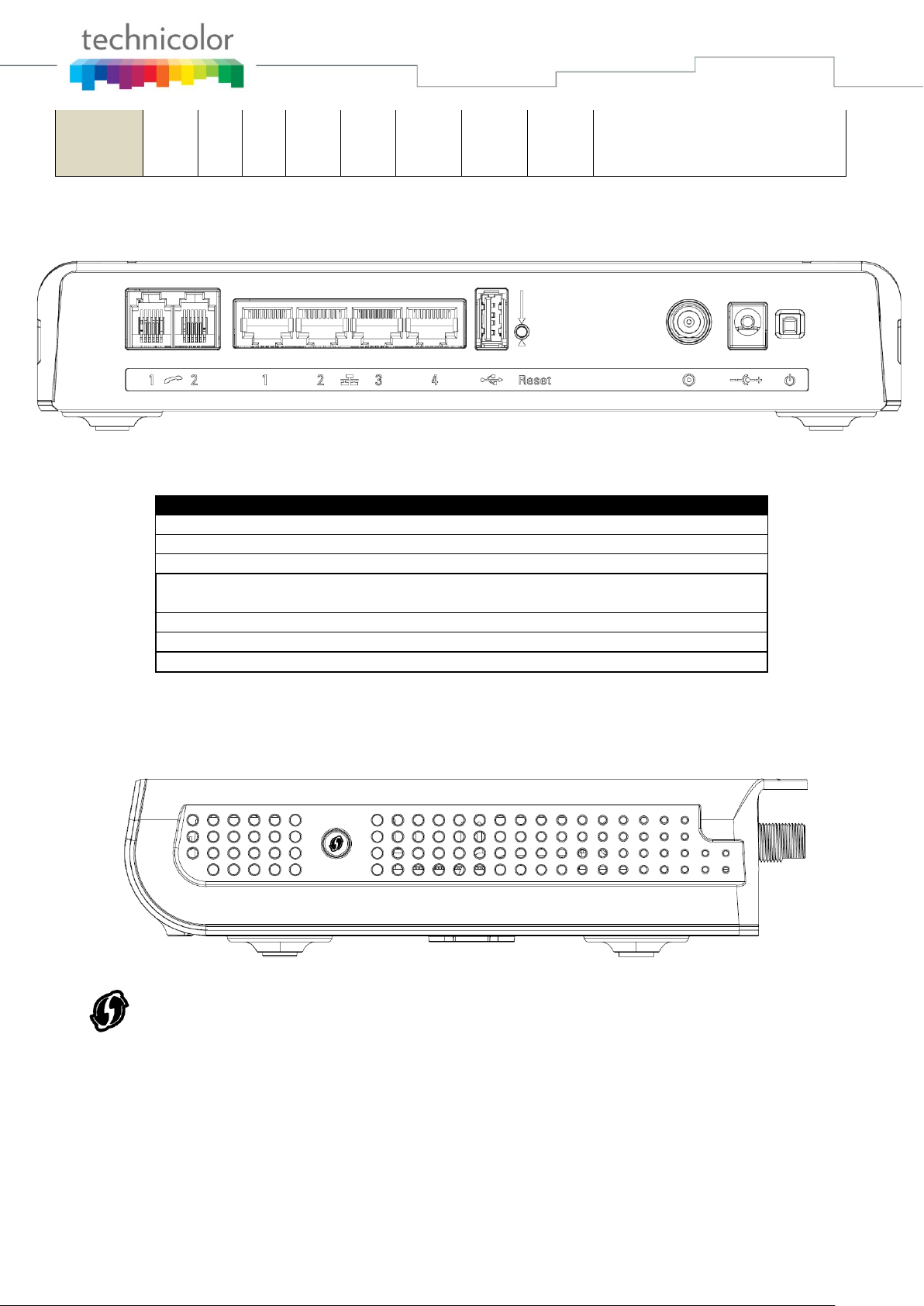
Rear Panel
Connector
Description
Power Switch
Power on, off the Cable modem.
Power Jack
Connector for DC12V.
Cable
Connector for the cable network.
Reset
To restart the modem or press over 5 seconds can
default the modem.
USB Host
USB 2.0 connector
Etherent
4 Gige Ethernet ports, RJ-45 connector.
Phone1/ Phone2
2 Phone RJ11 Connectors.
WPS – Indicates the status of the WPS functionality.
Table 1-1 LED behavior
Fig. 1-2 Rear Panel
Table 1-2 Rear Panel description
Side Panel for WPS
Fig. 1-3 Side Panel
WPS button: Wi-Fi Protected SetupTM. This button can be used to:
Secure the connection with another device (PC for example) using WPS protocol. A long press (press
2 more seconds) on the button allows you to enable the association of the modem with a PC or other
equipment.
After link establish. A short press on the button, switch on/off Wi-Fi.
Page 13 / 84
Page 14
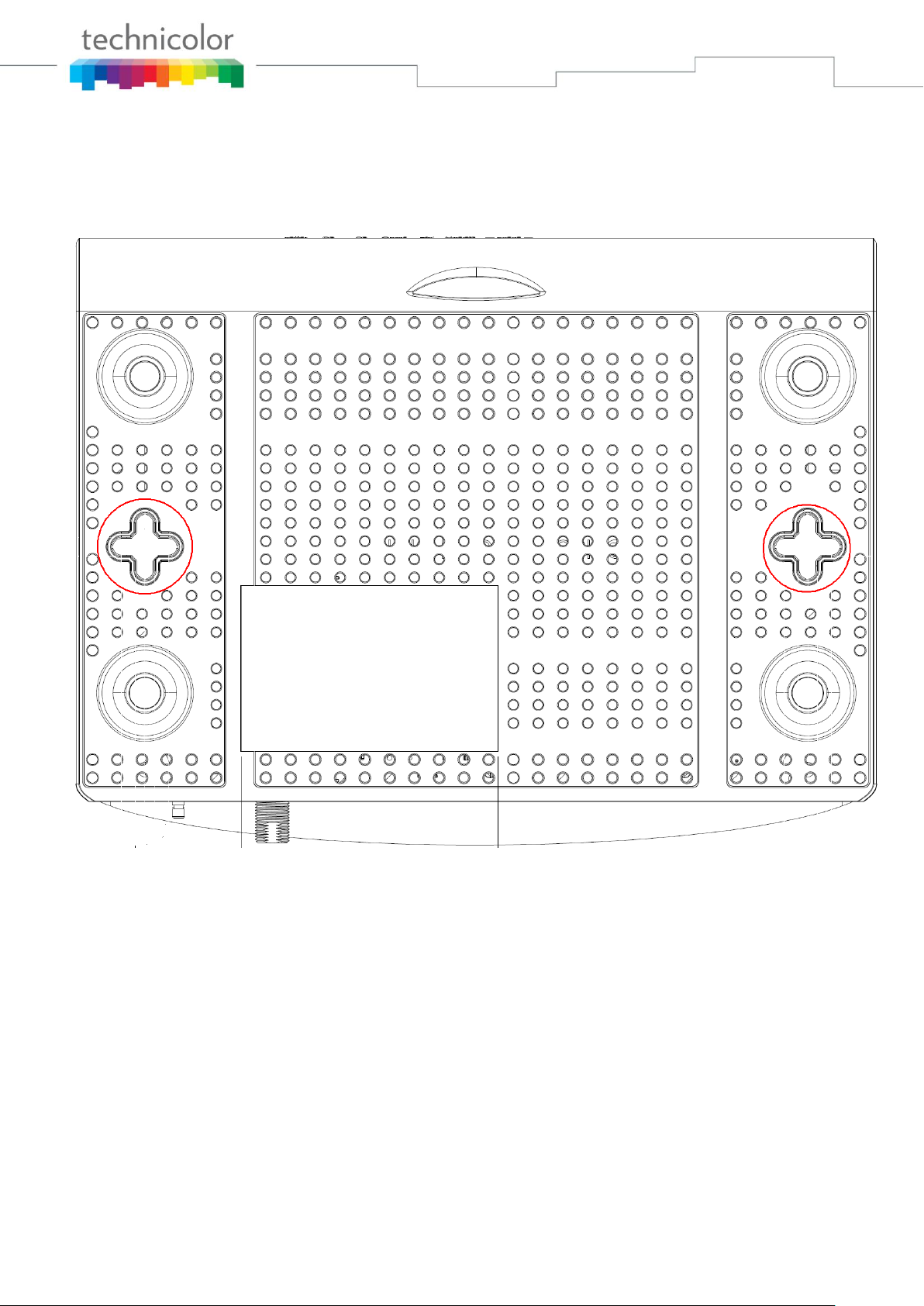
Wall Mounting
This article will show the user through the process of wall-mounting the Wireless Voice Gateway
The Adapter has two wall-mount slots on its back panel.
Two screws are needed to mount the Adapter.
To do this:
1. Ensure that the wall you use is smooth, flat, dry and sturdy and use the 2 screw holes
2. Fix the screws into wall, leaving their heads 3 mm (0.12 inch) clear of the wall surface.
3. Remove any connections to the unit and locate it over the screw heads. When in line,
Fig. 1-4 Wall Mounting
which are 101.6 mm (4 inches) apart from each other.
gently push the unit on to the wall and move it downwards to secure.
Page 14 / 84
Page 15
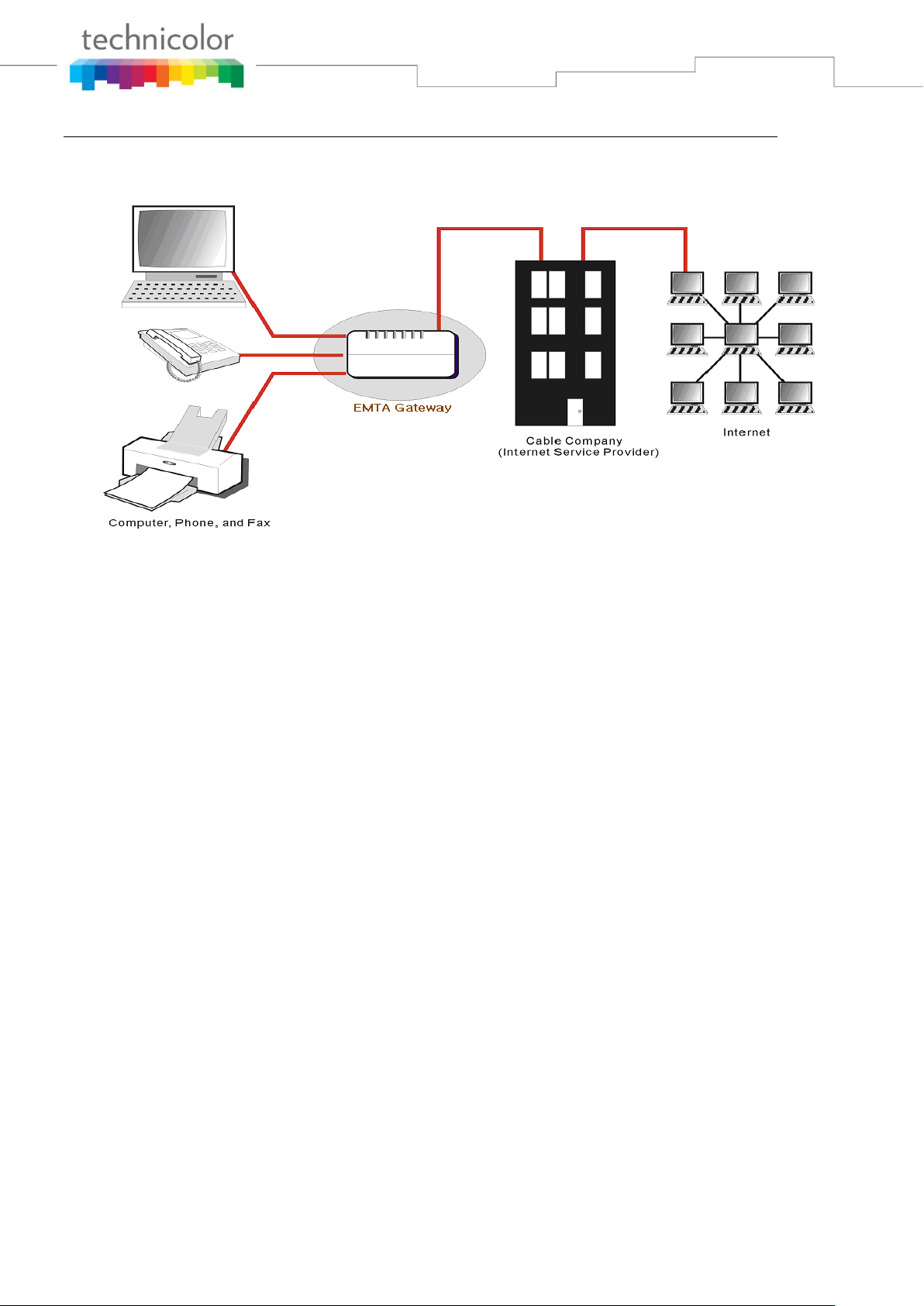
Relationship among the Devices
This illustration shows a cable company that offers DOCSIS/Euro-DOCSIS and PacketCable/EuroPacketCable compliant voice/data services.
Fig. 1-5 Connection overview
What the Modem Does
The Wireless Voice Gateway provides high-speed Internet access as well as cost-effective, toll-quality
telephone voice and fax/modem services over residential, commercial, and education subscribers on
public and private networks via an existing CATV infrastructure. It can inter-operate with the
PacketCable compliant head-end equipment and provide the IP-based voice communications. The IP
traffic can transfer between the Wireless Voice Gateway and DOCSIS/Euro-DOCSIS compliant head-end
equipment. The data security secures upstream and downstream communications.
What the Modem Needs to Do Its Job
The Right Cable Company: Make sure your local cable company provides data services that use
cable TV industry-standard DOCSIS/Euro-DOCSIS compliant and PacketCable/EuroPacketCable compliant technology.
The Internet/Telephony Service Provider (ISP/TSP): Your cable company provides you access
to an Internet Service Provider (ISP) and Telephony Service Provider (TSP). The ISP is your
gateway to the Internet and provides you with a pipeline to access Internet content on the World
Wide Web (WWW). The TSP provides you with telephony access to other modems or other
telephony services over the Public Switched Telephone Network (PSTN).
Check with your cable company to make sure you have everything you need to begin; they’ll know if you
need to install special software or re-configure your computer to make your cable internet service work
for you.
Page 15 / 84
Page 16

Contact Your Local Cable Company
You will need to contact your cable company to establish an Internet account before you can use your
gateway. You should have the following information ready (which you will find on the sticker on the
gateway):
The serial number
The model number
The Cable Modem (CM) Media Access Control (MAC) address
The Terminal Adapter (EMTA) MAC address
Security information: Service Set Identifier (SSID), Encryption key / passphrase (WPA2-PSK by
default), channel number. Default values are indicated underneath the modem on the sticker.
Please check the following with the cable company
The cable service to your home supports DOCSIS/Euro-DOCSIS compliant two-way modem
access.
Your internet account has been set up. (The Media Terminal Adapter will provide data service if
the cable account is set up but no telephony service is available.)
You have a cable outlet near your PC and it is ready for Cable Modem service.
Note: It is important to supply power to the modem at all times. Keeping your modem plugged in will
keep it connected to the Internet. This means that it will always be ready whenever you need.
Important Information
Your cable company should always be consulted before installing a new cable outlet. Do not attempt any
rewiring without contacting your cable company first.
Please verify the following on the Wireless Voice Gateway
The Power LED should be lighted when plug-in the power supply.
Connecting the Wireless Voice Gateway to a Single Computer
This section of the manual explains how to connect your Wireless Voice Gateway to the Ethernet port on
your computer and install the necessary software. Please refer to Figure 1-5 to help you connect your
Digital Cable Modem for the best possible connection.
Page 16 / 84
Page 17
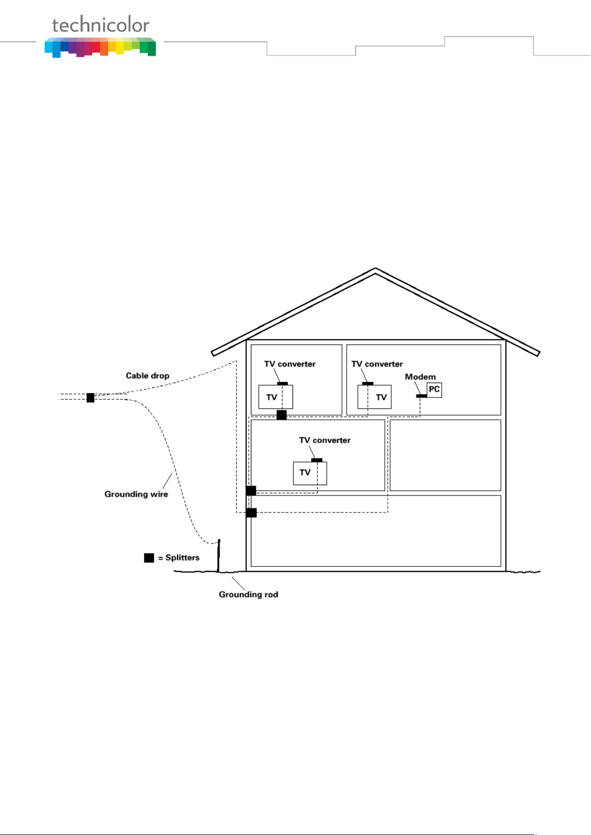
Attaching the Cable TV Wire to the Wireless Voice Gateway
1. Locate the Cable TV wire. You may find it one of three ways:
a. Connected directly to a TV, a Cable TV converter box, or VCR. The line will be connected to
the jack, which should be labeled either IN, CABLE IN, CATV, CATV IN, etc.
b. Connected to a wall-mounted cable outlet.
c. Coming out from under a baseboard heater or other location. See Figure 1-6 for the wiring
example.
Notes: For optimum performance, be sure to connect your
Wireless Voice Gateway to the first point the cable enters
your home. The splitter must be rated for at least 1GHz.
Fig. 1-6 Basic Home Wiring
Page 17 / 84
Page 18
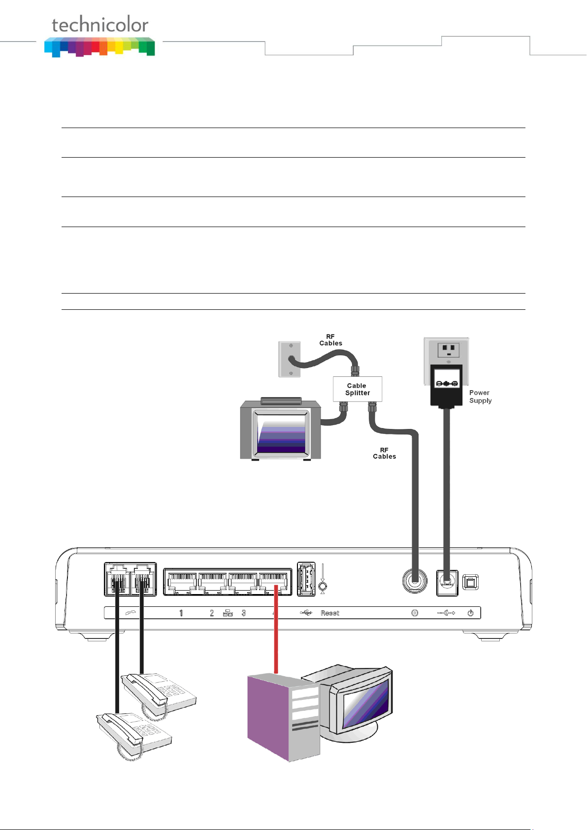
Installation procedure for connecting to the Ethernet interface
Follow these steps for proper installation.
Plug the coaxial cable to the cable wall outlet and the other end to the modem’s cable connector.
Note: To ensure a fast registration of the modem, the coaxial cable must be connected to
the modem before it is powered on.
Plug the power supply into the socket of the cable modem and two-pin plug in the AC outlet then press
the Power Switch, power on the modem.
Note: Only use the power supply that comes with the modem. Using another power supply
can cause damage to the product, and will void the warranty.
Connect an Ethernet cable (direct connection, see below) to the Ethernet port at the back of the computer,
and the other end to the ETHERNET port on the rear panel of the cable modem. The modem will seek the
appropriate cable signal on the cable television network and go through the initial registration process on
its own. The modem is ready for data transfer after the green LED "ONLINE" is lit continuously.
Note: the button "reset" at the back of the modem is used primarily for maintenance.
Fig. 1-7 Connect to the Modem
Page 18 / 84
Page 19

Telephone or Fax Connection
When properly connected, most telephony devices can be used with the Wireless Voice Gateway just as
with a conventional telephone service. To make a normal telephone call, pick up the handset; listen for a
dial tone, then dial the desired number. For services such as call waiting, use the hook switch (or FLASH
button) to change calls. The following procedures describe some of the possible connection schemes for
using telephony devices with the Wireless Voice Gateway.
1. Connect a standard phone line cord directly from the phone (fax machine, answering machine, caller
ID box, etc.) to one of the LINE jacks on the Wireless Voice Gateway.
2. If there is a phone line in your home which is NOT connected to another telephone service provider,
connect a standard phone line cord from a jack on this line to one of the LINE jacks of the Wireless
Voice Gateway. Connect a standard phone line cord directly from the phone (fax machine, answering
machine, caller ID box, etc.) to one of the other jacks in the house that uses that line.
3. If you have a multi-line telephone, connect a standard phone line cord (not an RJ-14 type line cord)
from the phone to the LINE jacks on the Wireless Voice Gateway. (Other phones can be added to
each line by using standard phone line splitters.)
Page 19 / 84
Page 20
CHAPTER 2: WEB CONFIGURATION
To make sure that you can access the Internet successfully, please check the following first.
1. Make sure the connection (through Ethernet) between the Wireless Voice Gateway and your
computer is OK.
2. Make sure the TCP/IP protocol is set properly.
3. Subscribe to a Cable Company.
Accessing the Web Configuration
The Wireless Voice Gateway offers local management capability through a built-in HTTP server and a
number of diagnostic and configuration web pages. You can configure the settings on the web page and
save them to the device.
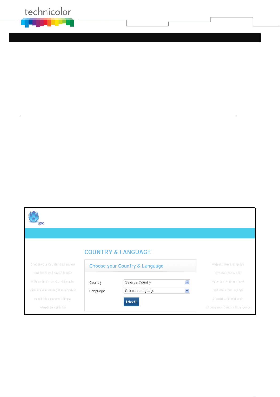
Once your host PC is properly configured; please proceed as follows:
1. Start your web browser and type the private IP address of the Wireless Voice Gateway on
the URL field: 192.168.0.1
2. After connecting to the device, you will be prompted to select a Country and Language.
This page will be brought to you at the first login if the device has been set to user or
operator factory defaults. Select the country and language that you preferred and then click
“Next” for proceeding to Login page.
Fig2-1 Country and Language page
Page 20 / 84
Page 21
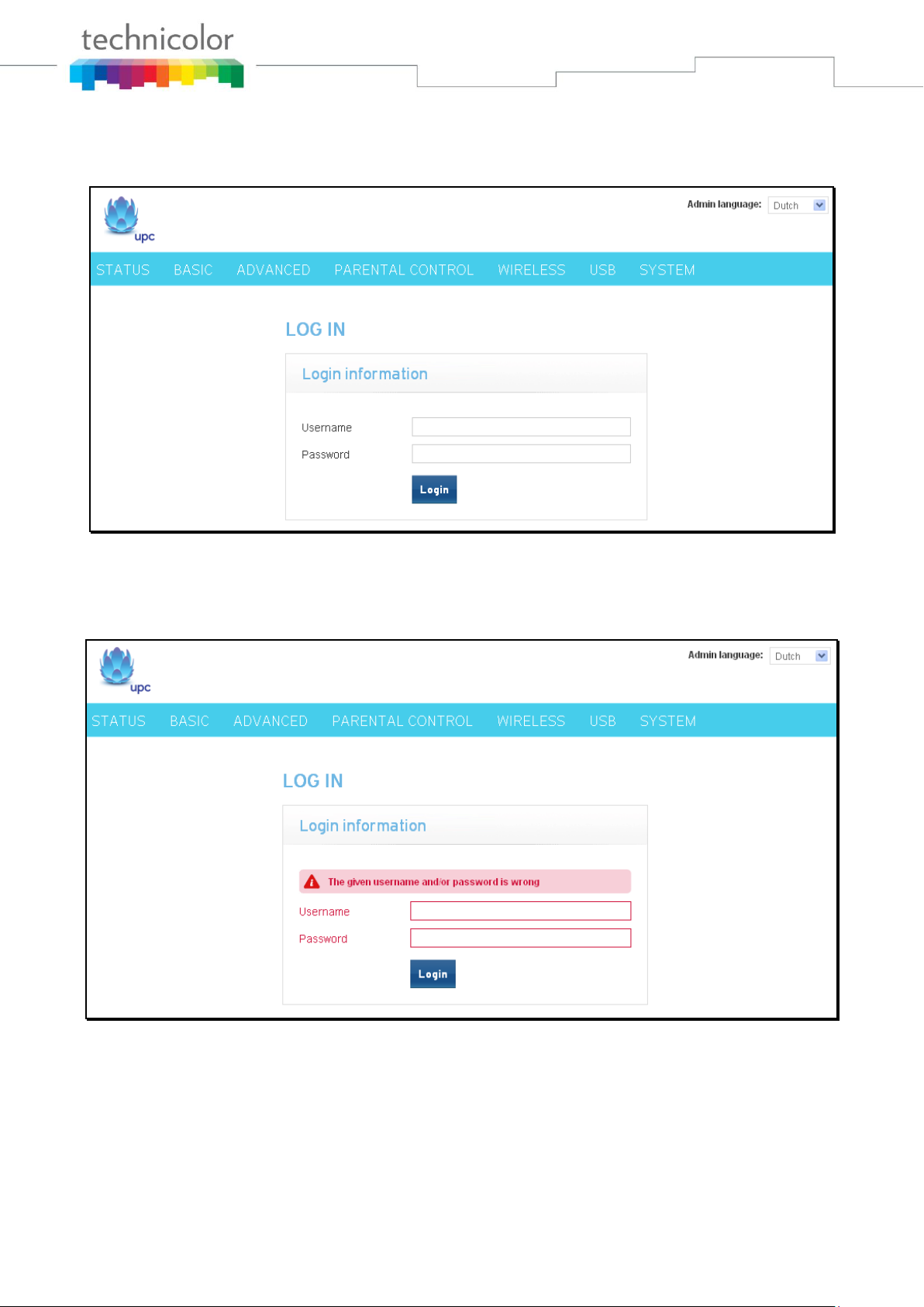
3. You will be prompted to enter username and password if this is not the first login. By
default, the username is “admin” and the password is “admin”.
Fig2-2 Login page
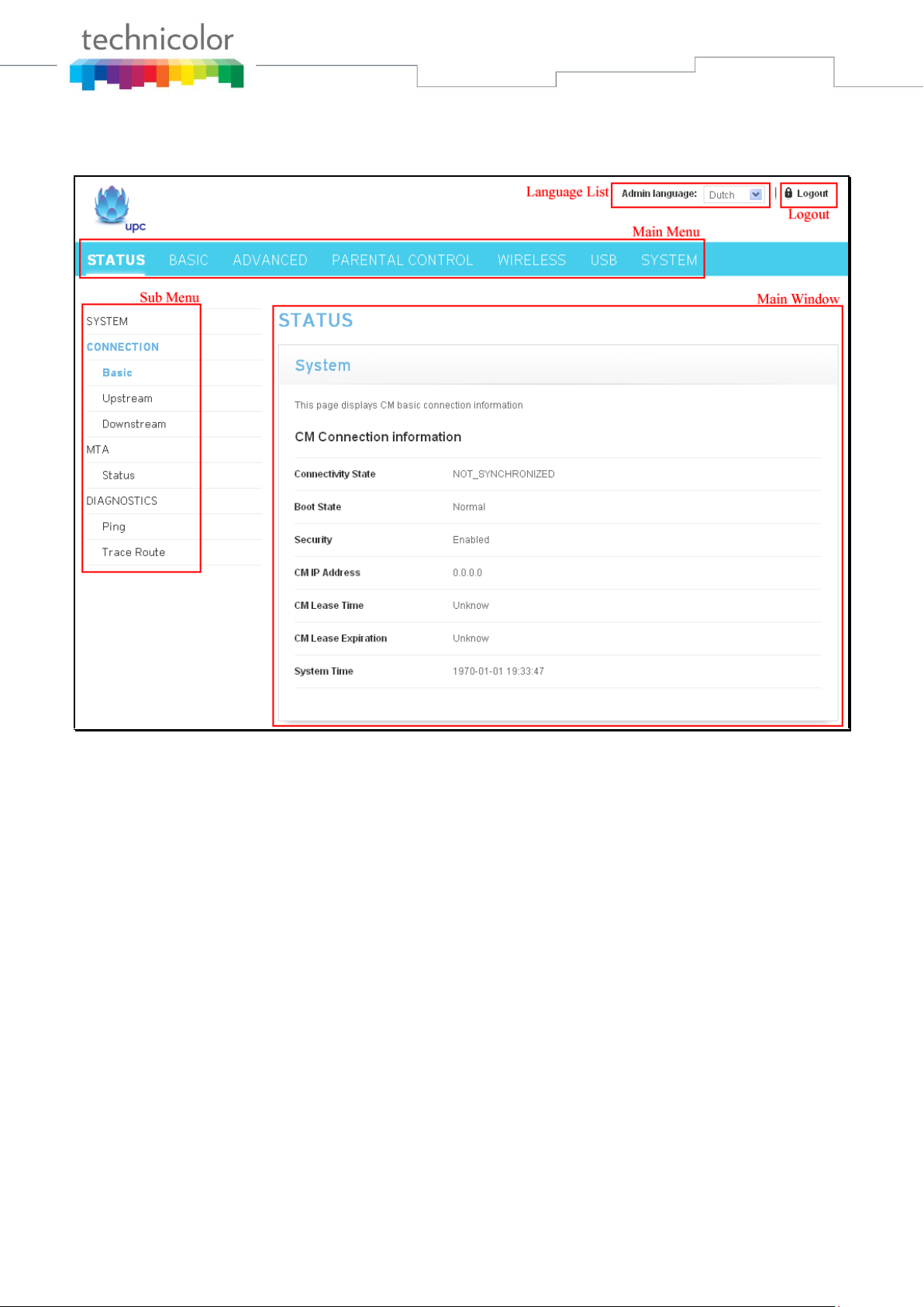
If you login successfully, the main page will appear.
The following page will be displayed if the given username or password is wrong.
Fig2-3 Wrong username/password page
Page 21 / 84
Page 22
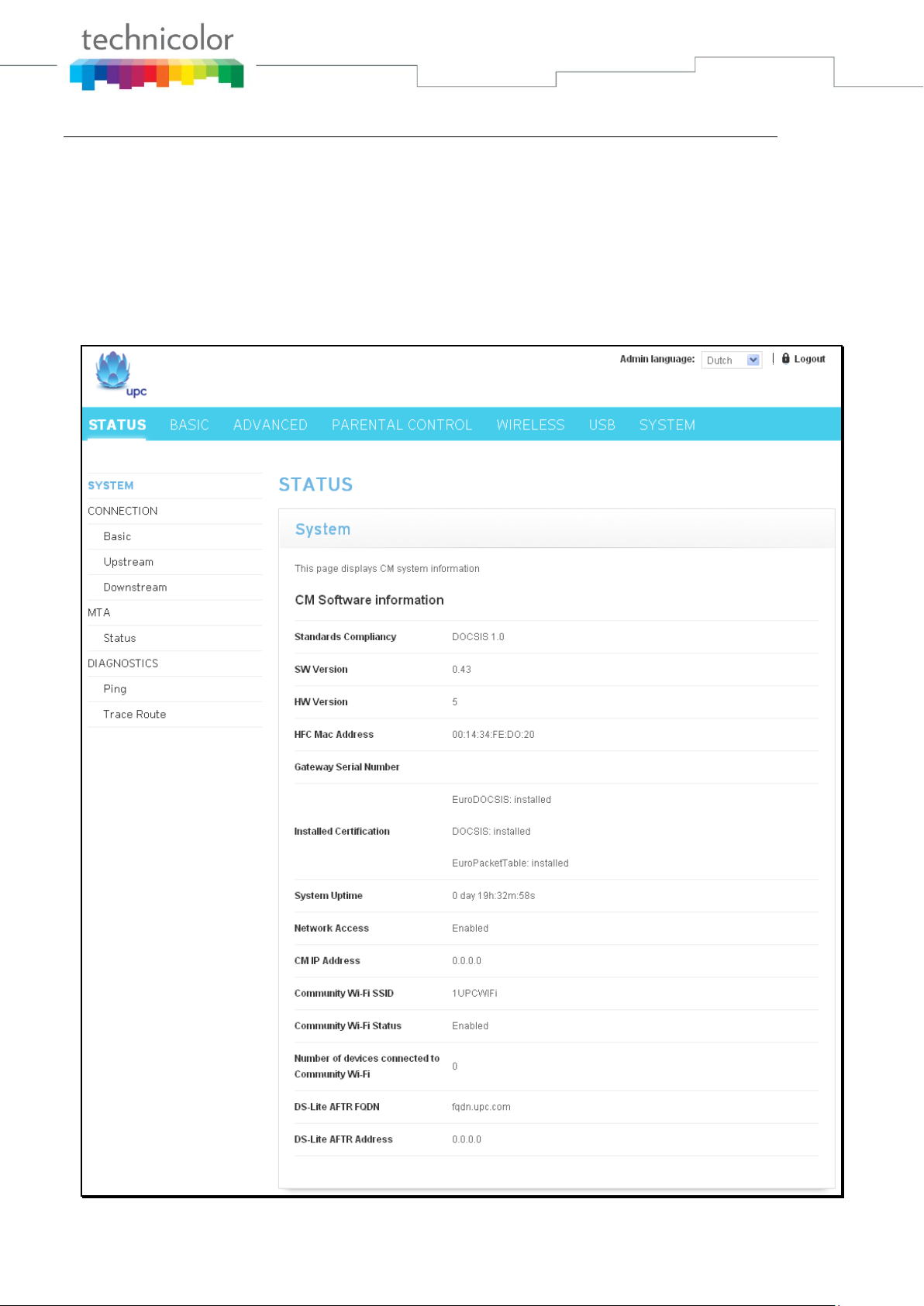
Outline of Web Manager
The main screen will be shown as below.
Fig. 2-4 Outline of Web Manager
Main Menu: the hyperlinks on the top of the page, including STATUS, BASIC, ADVANCED,
PARENTAL CONTROL, WIRELESS and SYSTEM items
Sub Menu: the sidebar on the left side of the page indicates the title of this management interface,
e.g., Status in this example
Main Window: the current workspace of the web management, containing configuration or status
information
Language List: List all of the language supported. Click the drop list and select the language that
you preferred.
Logout: Click “Logout” for logging out.
For easy navigation, the pages are organized in groups with group in names main menu. Individual page
names within each group are provided in the sub menu and sidebar. So to navigate to a page, click the
group hyperlink at the top, then the sub menu for the function, finally choose the title on the sidebar.
Your cable company may not support the reporting of some items of information listed on your gateway’s
internal web pages. In such cases, the information field appears blank. This is normal.
Page 22 / 84
Page 23
Status – Status Web Page Group
1. System
This page displays system information about your cable modem.
The CM Software information section of this page shows how long your gateway has operated since last
time being powered up, and some key information the Cable Modem received during the initialization
process with your cable company. If Network Access shows “Allowed,” then your cable company has
configured your gateway to have Internet connectivity. If not, you may not have Internet access, and
should contact your cable company to resolve this.
Fig.2-5 Status\System
Page 23 / 84
Page 24
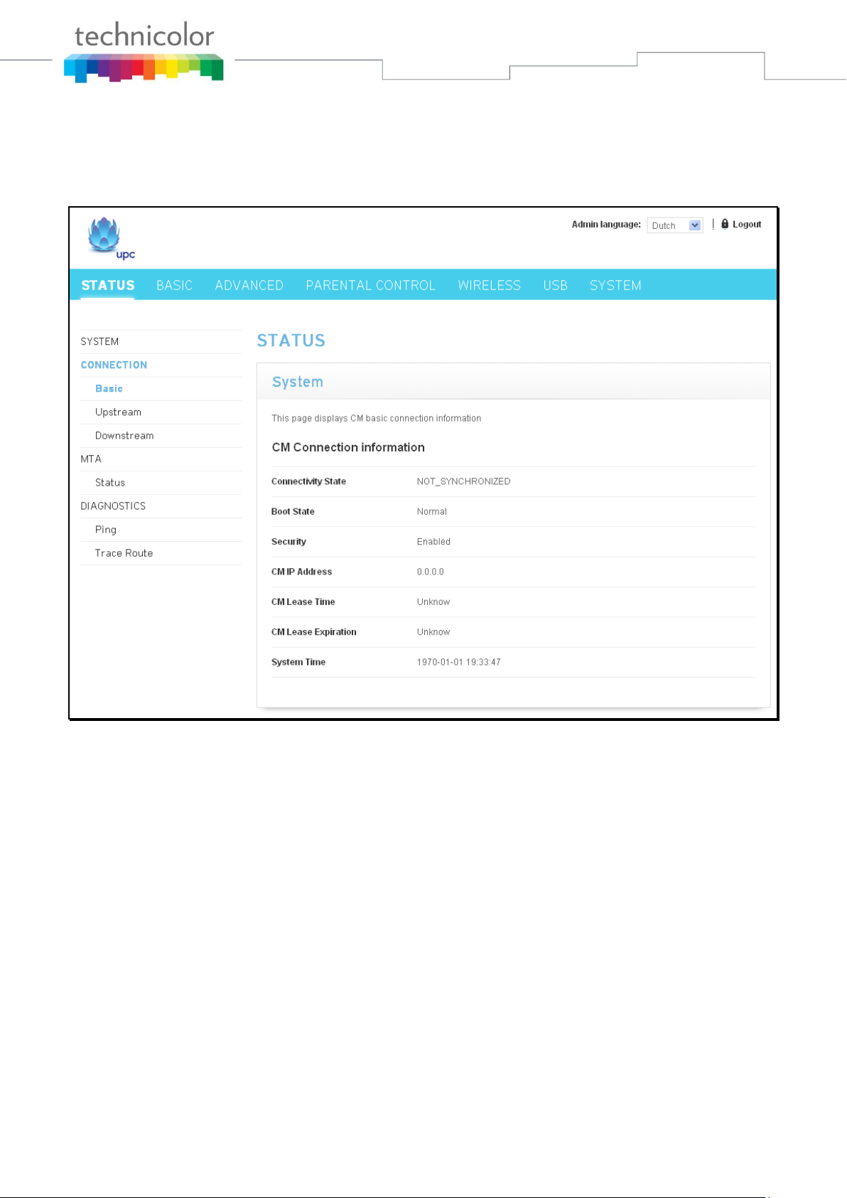
2. Connection/Basic
This page reports current CM basic connection information containing Connectivity State, Boot State,
Security, CM IP address, Lease Time, Lease Expiration and current System time. The information can be
useful to your cable company’s support technician if you’re having problems.
Fig. 2-6 Status\Connection\Basic
Page 24 / 84
Page 25
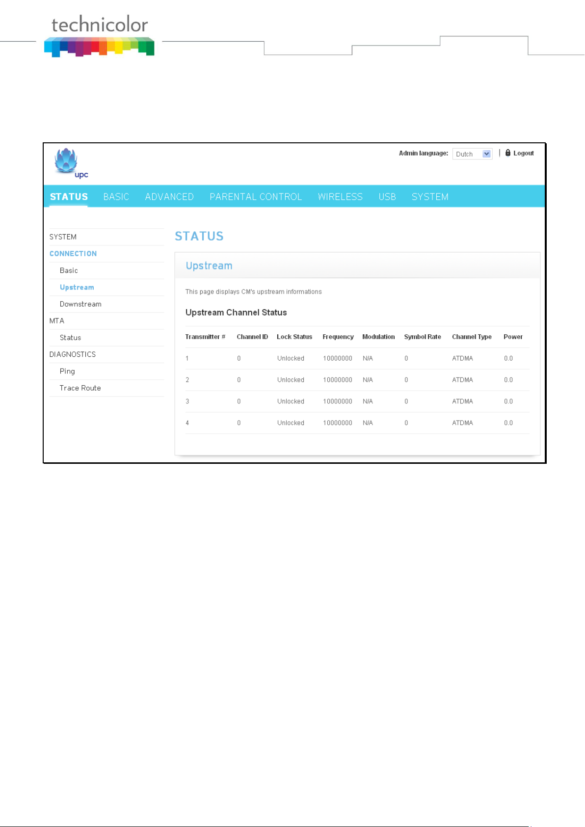
3. Connection/Upstream
This page reports current CM’s upstream information containing Transmitter #, Channel ID, Lock Status,
Frequency, Modulation, Symbol Rate, Channel Type and Power. The information can be useful to your
cable company’s support technician if you’re having problems.
Fig. 2-7 Status\Connection\Upstream
Page 25 / 84
Page 26
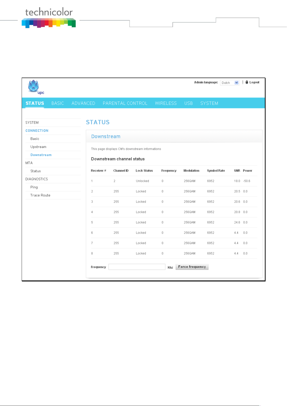
4. Connection/Downstream
This page reports current CM’s downstream information containing Receiver #, Channel ID, Lock Status,
Frequency, Modulation, Symbol Rate, SNR and Power. The information can be useful to your cable
company’s support technician if you’re having problems. By entering frequency in KHz and clicking
“Force frequency” button, you can force the CM locking to the specified frequency.
Fig. 2-8 Status\Connection\Downstream
Page 26 / 84
Page 27

5. MTA/Status
This page displays the initialization status of the MTA containing Telephony DHCP, Security, TFTP, Call
Server and Provisioning Status. The information can be useful to your cable company’s support
technician if you’re having problems.
The MAC List state can be found at the bottom of this page. It reports the current state of Line1 and
Line2.
Fig. 2-9 Status\MTA\Status
Page 27 / 84
Page 28

6. Diagnostics/Ping
This page can be used for determining the quality of your network connection. By setting up the
Destination IP address, Packet size, Packet count and then clicking “Start” button, you can check and
determine the quality of network connection. The result of Ping will be displayed at the frame under
Packet count. You can click the “Abort” button at any time during Ping test to abort the test. The
information can be useful to your cable company’s support technician if you’re having problems.
Fig. 2-10 Status\Diagnostics\Ping
Page 28 / 84
Page 29

7. Diagnostics/Trace Route
With this page you can perform trace route to display the route (path) and measure transit delays of
packets. In order to do trace route, a host IP and maximum TTL must be entered prior to start. Host IP is
the destination that you plan to trace route to. The value of MAX TTL ranges from 1 to 30 seconds.
Result of trace route will be displayed in ping text frame. You can click the “Abort” button at any time
during trace route test to abort the test. The information can be useful to your cable company’s support
technician if you’re having problems.
Fig. 2-11 Status\Diagnostics\Trace Route
Page 29 / 84
Page 30
Basic – Basic Web Page Group
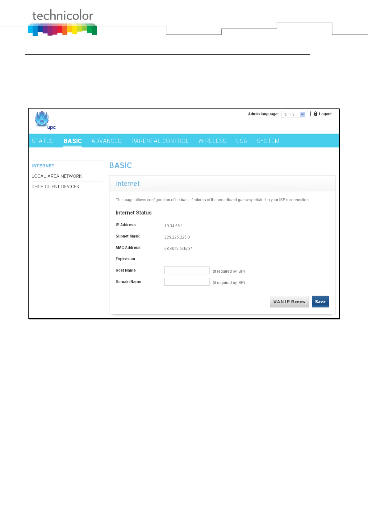
1. Internet
This page shows you the basic configuration of broadband gateway related to your MSO’s connection. It
allows configuration of Host Name and Domain Name if needed.
Clicking “WAN IP Renew” button will force the modem renewing WAN IP immediately.
Fig.2-12 Basic\Internet
Page 30 / 84
Page 31

2. Local Area Network
This page allows you to configure Local Area Network, DHCP server, DNS server and Domain Name.
Fig. 2-13 Basic\Local Area Network
Page 31 / 84
Page 32

3. DHCP Client Devices
This page reports current DHCP client information containing Mac Address, IP Address and Time
expiration of each client if the DHCP server was enabled in Local Area Network page.
Fig. 2-14 Basic\DHCP Client Devices
Page 32 / 84
Page 33

Advanced – Advanced Web Page Group
1. Options
This page allows you to configure router options. You can activate settings by checking them and clicking
“Save” button.
Fig.2-15 Advanced\Options
WAN Blocking prevents others on the WAN side from being able to ping your gateway. With WAN
Blocking enabled, your gateway will not respond to pings it receives, effectively “hiding” your
gateway.
IPSec Pass Through enables IPSec type packets to pass WAN LAN. IPSec (IP Security) is a
security mechanism used in Virtual Private Networks (VPNs).
PPTP Pass Through enables PPTP type packets to pass WAN LAN. PPTP (Point to Point
Tunneling Protocol) is another mechanism sometimes used in VPNs.
Multicast enables multicast traffic to pass WAN LAN. You may need to enable this to see some
types of broadcast streaming and content on the Internet.
UPnP Universal Plug and Play (UPnP) helps devices, such as Internet appliances and computers,
access the network and connect to other devices as needed. UPnP devices can automatically discover
the services from other registered UPnP devices on the network.
Page 33 / 84
Page 34

2. IP Filters
This page enables you to enter the IP address ranges of PCs on your LAN that you don’t want to have
outbound access to the WAN. These PCs can still communicate with each other on your LAN, but
packets they send to WAN addresses are blocked by the gateway.
Fig. 2-16 Advanced\IP Filters
You can add a blank row to the list by clicking “Add row” button. Entering the IP address range of PCs
on your LAN and then clicking “Save” button for saving the configuration.
Check the “Delete” option of a row and then clicking “Save” button for deleting the row.
Page 34 / 84
Page 35

3. MAC Filters
This page enables you to enter the MAC address of specific PCs on your LAN that you do not wish to
have outbound access to the WAN. As with IP filtering, these PCs can still communicate with each other
through the gateway, but packets they send to WAN addresses are blocked.
Fig. 2-17 Advanced\MAC Filters
You can add a blank row to the list by clicking “Add row” button. Entering the MAC address of PC on
your LAN and then clicking “Save” button for saving the configuration.
Check the “Delete” option of a row and then clicking “Save” button for deleting the row.
Page 35 / 84
Page 36

4. Port Filters
This page allows you to enter ranges of destination ports (applications) that you don’t want your LAN
PCs to send packets to. Any packets your LAN PCs send to these destination ports will be blocked. For
example, you could block access to worldwide web browsing (http = port 80) but still allow email service
(SMTP port 25 and POP-3 port 110). To enable port filtering, set Start Port and End Port for each range,
and click Apply. To block only one port, set both Start and End ports with the same value.
Fig.2-18 Advanced\Port Filters
You can add a blank row to the list by clicking “Add row” button. Entering the port range and protocol
that you want to block and then clicking “Save” button for saving the configuration.
Check the “Delete” option of a row and then clicking “Save” button for deleting the row.
The protocol option can be Both, UDP or TCP. Both of UDP and TCP port will be blocked if “Both” was
selected.
Page 36 / 84
Page 37

5. Forwarding
For LAN WAN communications, the gateway normally only allows you to originate an IP connection
with a PC on the WAN; it will ignore attempts of the WAN PC to originate a connection onto your PC.
This protects you from malicious attacks from outsiders. However, sometimes you may wish for anyone
outside to be able to originate a connection to a particular PC on your LAN if the destination port
(application) matches one you specify.
Fig. 2-19 Advanced\Forwarding
You can add a blank row to the list by clicking “Add row” button. Entering the public port range, target
IP address, target port range and protocol that you want to forward and then clicking “Save” button for
saving the configuration.
Check the “Delete” option of a row and then clicking “Save” button for deleting the row.
The protocol option can be Both, UDP or TCP. Both of UDP and TCP port will be blocked if “Both” was
selected.
Page 37 / 84
Page 38

6. Port Triggers
Some Internet activities, such as interactive gaming, require that a PC on the WAN side of your gateway
be able to originate connections during the game with your game playing PC on the LAN side. You could
use the Advanced-Forwarding web page to construct a forwarding rule during the game, and then remove
it afterwards (to restore full protection to your LAN PC) to facilitate this. Port triggering is an elegant
mechanism that does this work for you, each time you play the game.
Fig. 2-20 Advanced\Port Triggers
Port Triggering works as follows. Imagine you want to play a particular game with PCs somewhere on
the Internet. You make one time effort to set up a Port Trigger for that game, by entering into Trigger
Start Port and Tigger End Port the range of destination ports your game will be sending to, and
entering into Target Start Port the range of destination ports the other player (on the WAN side) will be
sending to (ports your PC’s game receives on). Application programs like games publish this information
in user manuals. Later, each time you play the game, the gateway automatically creates the forwarding
rule necessary. This rule is valid until 10 minutes after it sees game activity stop. After 10 minutes, the
rule becomes inactive until the next matched outgoing traffic arrives.
e.g., suppose you specify Trigger Range from 6660 to 6670 and Target Range from 113 to 113. An
outbound packet arrives at the gateway with your game-playing PC source IP address 192.168.0.10,
destination port 666 over TCP/IP. This destination port is within the Trigger destined for port 113 to your
game-playing PC at 192.168.0.10.
Page 38 / 84
Page 39

7. DMZ Host
Use this page to designate one PC on your LAN that should be left accessible to all PCs from the WAN
side, for all ports. e.g., if you put an HTTP server on this machine, anyone will be able to access that
HTTP server by using your gateway IP address as the destination. A setting of “0” indicates NO DMZ
PC. “Host” is another Internet term for a PC connected to the Internet.
Fig.2-21 Advanced\DMZ Host
Page 39 / 84
Page 40

8. Firewall
These pages allow you to enable, disable, and configure a variety of firewall features associated with web
browsing, which uses the HTTP protocol and transports HTML web pages. On these pages, you designate
the gateway packet types you want to have forwarded or blocked. You can activate settings by checking
them and clicking “Save” button.
The web-related filtering features you can activate from the Firewall page include Filter Cookies, Filter
Java Applets, Filter ActiveX, Filter Popup Windows, Block Fragmented IP Packets, Port Scan Detection,
IP Flood Detection, and Firewall Protection.
Fig. 2-22 Advanced\Firewall
Page 40 / 84
Page 41

Parental Control – Parental Control Web Page Group
1. Device Rules
This page allows you to add and delete Web Site and ToD filter for specified Device. You can save the
settings by clicking “Save” button.
Fig.2-23 Parental Control\Device Rules
A new device can be added to the list by clicking “Add a Device” button. The “Add a Device” dialogue
will be displayed. Please enter Device Name and MAC address for the device that you want adding to the
list and then clicking “Add Device” button.
Fig.2-24 Parental Control\Add Device
Page 41 / 84
Page 42

Web Site Filters: The filter can be defined in WEB Site Filters page. Select the filter from the drop
down list and click “Save” button for saving it.
ToD Filters: The filter can be defined in ToD Filters page. Select the filter from the drop down list
and click “Save” button for saving it.
Trusted: Check the Trusted checkbutton and click “Save” button for making the device be trusted.
Delete: Check the delete checkbutton and click “Save” button for deleting the device.
Page 42 / 84
Page 43

2. Basic Setup
This page allows you to enable Parental Control and bypass all blocks in Parental Control.
Fig. 2-25 Parental Control\Basic Setup
Enable Parental Control: By clicking drop list of Enable Parental Control, select Enabled, enter
password and then clicking “Save” button for enabling Parental Control.
Password: Enter a password for configuring Parental Control. The same password MUST be enter
in field Retype Password.
Retype Password: Enter same password as the one in Password field.
Access Duration: It is the available time of the Override Password.
Override Password: It is used to bypass all blocks in Parental Control.
Mac Address : Enter the MAC address of computers that you trusted and then clicking the “Add to
trusted computers” for adding it.
Remove selected : Select computer that you want to remove from the Trusted Computers list and
then clicking the “Remove selected” button for removing it.
Page 43 / 84
Page 44

3. WEB Site Filters
This page allows you to configure the web sites that can be reached, should be blocked, or should be
blocked if specific keywords were found. You can add the configuration to a new policy or remove a
policy from the list.
Fig. 2-26 Parental Control\WEB Site Filters
Policies: A list of available WEB site filter policy. Select a policy from the drop list and then click
“Submit” button for making it the current policy. Select a policy from the drop list and then click
“Remove current policy” for removing it. A new policy can be added by clicking “Add new policy”
button. Entering policy name to “Add a Policy” dialogue page and clicking “Create” button for
adding it to the list
Page 44 / 84
Page 45

Fig. 2-27 Parental Control\Add a Policy
Keywords: WEB pages contain the keywords list in the filed will be blocked.
Blocked domains: Domains list in this filed will be blocked.
Allowed domains: Domains list in this filed will be allowed for accessing.
Page 45 / 84
Page 46

4. TOD Filters
Use this page to set rules that will block LAN side PCs from accessing the Internet, but only at specific
days and times. By clicking time block for selecting/deselecting a specific hour. Finally, click the
“Submit” button to save your settings.
Fig.2-28 Parental Control\TOD Filters
Policies: A list of available TOD filter policy. Select a policy from the drop list and then click
“Submit” button for making it the current policy. Select a policy from the drop list and then click
“Remove” for removing it. A new policy can be added by clicking “Add” button. Entering policy
name to “Add a Policy” dialogue page and clicking “Create” button for adding it to the list
Page 46 / 84
Page 47

Fig. 2-29 Parental Control\Add a Policy
To click on each hour block and making it in blue color will cause the modem to block Internet
traffic at that hour. To click on the blue block again to make it accessable.
Clear: Click “Clear” button for clearing all of block hour.
Inverse: Click “Inverse” button for reverse the status of all the hour blocks.
Page 47 / 84
Page 48

Wireless – Wireless Web Page Group
The Wireless web pages group enables a variety of settings that can provide secure and reliable wireless
communications for even the most demanding tech-savvy user.
The Wireless Voice Gateway offers a choice of 802.11b/g/n, WPA and WPA-PSK authentication of your
PCs to the gateway, 64 and 128 bit WEP encryption of communication between the gateway and your
PCs to guaranty security, and an Access Control List function that enables you to restrict wireless access
to only your specific PCs.
Performance
Because your wireless communication travels through the air, the factory default wireless channel setting
may not provide optimum performance in your home if you or your neighbors have other interfering
2.4GHz or 5 GHz devices such as cordless phones. If your wireless PC is experiencing very sluggish or
dramatically slower communication compared with the speed you achieve on your PC that is wired to the
gateway, try changing the channel number. See the 802.11b/g/n Basic Web Page discussion below for
details.
Authentication
Authentication enables you to restrict your gateway from communicating with any remote wireless PCs
that aren’t yours. The following minimum authentication-related changes to factory defaults are
recommended. See the 802.11b/g/n Basic and Access Control Web Page discussions below for details.
Network Name (SSID) – Set a unique name you choose
Network Type – Set to Open
Access Control List – Enter your wireless PCs’ MAC addresses
Security
Security secures or scrambles messages traveling through the air between your wireless PCs and the
gateway, so they can’t be observed by others. The following minimum security setting changes to factory
defaults are recommended. See the 802.11b/g/n Security Web Page discussion below for details.
Page 48 / 84
Page 49

1. 2.4 GHz\Radio
This page allows you to configure the access control of 2.4GHz AP.
Fig.2-30 Wireless\2.4GHz\Radio
Enable: It may help you to Enable or Disable the 2.4 GHz wireless function. To enable you need to
select Enabled, to disable you need to select Disabled.
SSID: The SSID for 2.4 GHz wireless function.
802.11 Mode: There are three different modes can be selected. Mixed, Disabled and Greenfield.
Channel: In 802.11 Band 2.4GHz, there are 1 to 13 channels. In 802.11 Band 5GHz, there are 36,
40, 44, 48 total 4 channels for all country. Choose the one that is suitable for this device.
Bandwidth: Select wireless channel width 20 MHz is for default value (bandwidth taken by
wireless signals of this access point.) It can be 20 MHz or 40 MHz.
Power: This setting decides the output power of this 2.4 GHz device. You may use it to economize
on electricity by selecting lower percentage of power output. Control the range of the AP by
adjusting the radio output power. The power can be 100%, 75%, 50% or 25%.
Page 49 / 84
Page 50

2. 2.4 GHz\Security
This page allows you to configure security of wireless.
Fig. 2-31 Wireless\2.4GHz\Security
Wireless security mode: The wireless security mode can be either WPA Personal or WPA.
Authentication: The method of authentication can be WPA/WPA2 or WPA.
Passphrase: You can enter ASCII codes into this field. The range is from 8 characters to 64
characters. For ASCII characters, you can key in 63 characters in this field. If you want to key in
64 characters, only hexadecimal characters can be used.
Retype Passphrase: Enter the passphrase again for confirmation.
Page 50 / 84
Page 51

3. 2.4 GHz\Advanced
This page allows configuring advance wireless settings.
Fig. 2-32 Wireless\2.4GHz\Advanced
Country: Please select the country code.
Mac Address: The MAC address for this wireless device will be displayed in this field
automatically.
Beacon Interval: Set the period of beacon transmissions to allow mobile stations to locate and
identify a BSS. The measure unit is “time units” (TU) of 1024 microseconds. (Value range:
1~65535)
DTIM Interval: The value you set here is used to inform mobile stations when multicast frames that
have been buffered at the Wireless Voice Gateway will be delivered and how often that delivery
occurs. (Value range: 1~255)
Fragment Threshold: Set the number of the fragmenting frames to make the data to be delivered
without errors induced by the interference. Frames longer than the value you set here are fragmented
before the initial transmission into fragments no longer than the value of the threshold. (Value range:
256~ 2346)
Page 51 / 84
Page 52

RTS Threshold: Set the value for sending a request to the destination. All the frames of a length
greater than the threshold that you set here will be sent with the four-way frame exchange. And, a
length less than or equal to the value that you set will not be proceeded by RTS. (Value range: 0~
2347)
WMM: Wi-Fi Multimedia (WMM) is a component of the IEEE 802.11e wireless LAN standard for
quality of service (QoS). The QoS assigns priority to the selected network traffic and prevents packet
collisions and delays thus improving VoIP calls and watching video over WLANs. It may help you
to Enable or Disable the WMM function. To enable you need to select Enabled, to disable you need
to select Disabled.
WMM Power Save: This field allows you to enable WMM Power Save-Support. To enable you
need to select Enabled, to disable you need to select Disabled.
Page 52 / 84
Page 53

4. 2.4 GHz\Access Control
This page allows configuring access control.
Fig.2-33 Wireless\2.4GHz\Access Control
Policies: Policy of access control settings. Two options can be selected. It can be either Allow List
or Deny List.
Mac Address: The MAC address list that allow of deny access.
Add row: Click ”Add row” for adding a new row of Mac Address.
Delete: Check ”Delete” of a raw and click”Save” button for deleting it.
Page 53 / 84
Page 54

5. 2.4 GHz\WPS
This page allows you to configure WPS setting. Wi-Fi Protected SetupTM (WPS) is an easy and secure
way of configuring and connecting your Wireless access point. In this case, the Wireless Voice Gateway
is the Access Point (AP), and Your PC (or Wireless Device) is called the STA. When configuring your
Wireless Network via WPS, Messages are exchanged between the STA and AP in order to configure the
Security Settings on both devices.
Fig. 2-34 Wireless\2.4GHz\WPS
WPS: It will help you to Enable or Disable the WPS feature. To enable you need to select WPS, to
disable you need to select Disabled.
PIN: This is the PIN for authentication. Enter the PIN and the click “PIN start” for start PIN
connection.
PBC: Click “PBC start” for starting it.
Page 54 / 84
Page 55

6. 5 GHz\Radio
This page allows you to configure the access control of 5 GHz AP.
Fig.2-35 Wireless\5 GHz\Radio
Enable: It may help you to Enable or Disable the 5 GHz wireless function. To enable you need to
select Enabled, to disable you need to select Disabled.
SSID: The SSID for 5 GHz wireless function.
802.11 Mode: There are three different modes can be selected. Mixed, Disabled and Greenfield.
Channel: In 802.11 Band 5GHz, there are 36, 40, 44, 48 total 4 channels for all country. Choose the
one that is suitable for this device.
Bandwidth: Select wireless channel width 20 MHz is for default value (bandwidth taken by
wireless signals of this access point.) It can be 20 MHz or 40 MHz.
Power: This setting decides the output power of this 5 GHz device. You may use it to economize on
electricity by selecting lower percentage of power output. Control the range of the AP by adjusting
the radio output power. The power can be 100%, 75%, 50% or 25%.
Page 55 / 84
Page 56

7. 5 GHz\Security
This page allows you to configure security of wireless.
Fig. 2-36 Wireless\5 GHz\Security
Wireless security mode: The wireless security mode can be either WPA Personal or WPA.
Authentication: The method of authentication can be WPA/WPA2 or WPA.
Passphrase: You can enter ASCII codes into this field. The range is from 8 characters to 64
characters. For ASCII characters, you can key in 63 characters in this field. If you want to key in
64 characters, only hexadecimal characters can be used.
Retype Passphrase: Enter the passphrase again for confirmation.
Page 56 / 84
Page 57

8. 5 GHz\Advanced
This page allows configuring advance wireless settings.
Fig. 2-37 Wireless\5 GHz\Advanced
Country: Please select the country code.
Mac Address: The MAC address for this wireless device will be displayed in this field
automatically.
Beacon Interval: Set the period of beacon transmissions to allow mobile stations to locate and
identify a BSS. The measure unit is “time units” (TU) of 1024 microseconds. (Value range:
1~65535)
DTIM Interval: The value you set here is used to inform mobile stations when multicast frames that
have been buffered at the Wireless Voice Gateway will be delivered and how often that delivery
occurs. (Value range: 1~255)
Fragment Threshold: Set the number of the fragmenting frames to make the data to be delivered
without errors induced by the interference. Frames longer than the value you set here are fragmented
before the initial transmission into fragments no longer than the value of the threshold. (Value range:
256~ 2346)
Page 57 / 84
Page 58

RTS Threshold: Set the value for sending a request to the destination. All the frames of a length
greater than the threshold that you set here will be sent with the four-way frame exchange. And, a
length less than or equal to the value that you set will not be proceeded by RTS. (Value range: 0~
2347)
WMM: Wi-Fi Multimedia (WMM) is a component of the IEEE 802.11e wireless LAN standard for
quality of service (QoS). The QoS assigns priority to the selected network traffic and prevents packet
collisions and delays thus improving VoIP calls and watching video over WLANs. It may help you
to Enable or Disable the WMM function. To enable you need to select Enabled, to disable you need
to select Disabled.
WMM Power Save: This field allows you to enable WMM Power Save-Support. To enable you
need to select Enabled, to disable you need to select Disabled.
Page 58 / 84
Page 59

9. 5 GHz\Access Control
This page allows you to configure access control.
Fig.2-38 Wireless\5 GHz\Access Control
Policies: Policy of access control settings. Two options can be selected. It can be either Allow List
or Deny List.
Mac Address: The MAC address list that allow of deny access.
Add row: Click ”Add row” for adding a new row of Mac Address.
Delete: Check ”Delete” of a raw and click”Save” button for deleting it.
Page 59 / 84
Page 60

10. 5 GHz\WPS
This page allows you to configure WPS setting.
Fig. 2-39 Wireless\5 GHz\WPS
WPS: It will help you to Enable or Disable the WPS feature. To enable you need to select WPS, to
disable you need to select Disabled.
PIN: This is the PIN for authentication. Enter the PIN and the click “PIN start” for start PIN
connection.
PBC: Click “PBC start” for starting it.
Page 60 / 84
Page 61

USB – USB Web Page Group
1. USB Basic
This page allows basic control of the USB devices shared over the network.
Enable USB Devices connected to the USB port: This field controls which USB device (Key or
Hard Disk) can be connected to the Gateway. "All" will authorize all USB devices. "Approved" will
authorize devices that have been previously approved on this gateway. "None" will block any USB
Device on the Gateway. To approve devices (PC), click on the button "Approved Devices"
Enable USB Devices to be Shared Storage: Yes or No to decide if you share or not the content of
the USB device. Click on "Storage Configuration" button to access the web pages to configure the
Storage Device.
Enable the Media Server (DLNA): Yes or No to activate or the not the DLNA Server (DLNA:
Digital Living Network Alliance). To configure the DLNA server, click on the button "Media Server
Configuration".
Fig.2-40 USB\USB Basic
Page 61 / 84
Page 62

2. Approuved Devices
This page allows the configuration of the USB storage device(s) shared over the network.
Add Available USB Devices as Approved USB Devices then apply changes. If you want to remove
USB devices, propose you press “Safely Remove Device” button first.
Fig. 2-41 USB\Approuved Devices
Page 62 / 84
Page 63

3. Storage Basic
This page shows the status of the USB folders shared over the network.
Basic option defines shared files in all approved devices and specified folders or only specified
folders. You can edit Shared Network Folders and observe the detail of folders.
Fig. 2-42 USB\Storage Basic
Page 63 / 84
Page 64

4. Storage Advanced
This page shows the status of the folders shared over the network.
Advanced option provides FTP option to share files as a FTP server.
Fig.2-43 USB\Storage Advanced
Page 64 / 84
Page 65

5. MEDIA SERVER
This page controls configuration and scanning of the Gateway's media server.
Choose Scan all Files will scan your approved USB devices for sharing files. Scan Files by Type for
specific file type or all of types for sharing. Choose file types form Available File Types to Selected
File Types.
Page 65 / 84
Page 66

Fig. 2-44 USB\Media Server
Page 66 / 84
Page 67

Fig. 2-44 USB\Media Server
Page 67 / 84
Page 68

System – System Web Page Group
1. Password
By default, the username is “admin” and the password is “admin”.
This is set by different actions (non exhaustive list):
- at the manufactory level,
- following a reset factory on the modem,
- following a reset from the operator,
- following a change by the user who wants to come back to the default setting after using its own
settings
When the current password is the default one, the user is strongly encouraged to change the default web
password.
At your first connection or while the password is the default one, a warning message is displayed on the
top banner of each Web configuration page. We want to encourage you to change the password in order
to enforce the security of your modem.
The password can be a maximum of 8 characters and is case sensitive. In addition, this page can be used
to restore the gateway to its original factory settings. Use this with caution, as all the settings you have
made will be lost. To perform this reset, set Restore Factory Defaults to Yes and click Apply. This has
the same effect as a factory reset using the rear panel reset switch, where you hold on the switch for 5
seconds, then release it.
Note: We are always suggesting you to modify the password. This is a basic protection against wrongful
access to the Gateway Web pages.
Fig.2-45 System\Password
Page 68 / 84
Page 69

2. Backup and Recovery\Backup
This page allows you to save your current settings locally on your PC. The default file name is
“GatewaySettings.bin”.
Please enter the password if you want to encrypt your configuration’s backup. The same password MUST
be entered to retype password field for the confirmation. Click the “Backup” button for saving the
configuration’s backup.
Fig. 2-46 System\Backup and Recovery\Backup
Page 69 / 84
Page 70

3. Backup and Recovery\Restore
This page allows you to restore settings previously saved locally on your PC. The default file name is
“GatewaySettings.bin”.
Please enter the password if you want to restore encrypted configuration’s backup. Click “Browse” button
and then select the configuration’s backup that you want to restore. Click the “Restore” button for
restoring the configuration’s backup.
Fig. 2-47 System\Backup and Recovery\Restore
Page 70 / 84
Page 71

4. Backup and Recovery\Factory Default
This page allows you to restore factory default settings.
To click the “Restore Defaults” button will restore System to the factory (default) settings.
Fig.2-48 System\Backup and Recovery\Factory Default
Page 71 / 84
Page 72

5. Log\Syslog
The Syslog page allows you to specify the IP address where a Syslog server is located on the LAN side
and select different types of firewall events that may occur. Then, each time such an event occurs,
notification is automatically sent to this log server. In order to use the Syslog server, you must select
Enabled from the drop list of Remote logging, specify the IP address of server, tick the levels and then
click the “Save” button.
Fig. 2-49 System\Log\Syslog
Page 72 / 84
Page 73

6. Log\Local Log
The gateway builds a log of firewall blocking actions that the firewall has taken. The log of levels
selected is visible on the screen. Using the Local Log page lets you tick the levels of log and show logs in
the log text frame. Tick the levels you need and click on “Save” button.
Fig. 2-50 System\Log\Local Log
Page 73 / 84
Page 74

CHAPTER 3: NETWORKING
Communications
Data communication involves the flow of packets of data from one device to another. These devices
include personal computers, Ethernet, cable modems, digital routers and switches, and highly integrated
devices that combine functions, like the Wireless Cable Gateway.
The gateway integrates the functionality often found in two separate devices into one. It’s both a cable
modem and an intelligent wireless voice gateway networking device that can provide a host of
networking features, such as NAT and firewall. Fig.3-1 illustrates this concept, with the cable modem
(CM) functionality on the left, and networking functionality on the right. In this figure, the numbered
arrows represent communication based on source and destination, as follows:
Fig.3-1 Communication between your PCs and the network side
Type of Communication
1. Communication between the Internet and your PCs
Example: The packets created by your request for a page stored at a web site, and the contents of that
page sent to your PC.
2. Communication between your cable company and the cable modem side
Example: When your cable modem starts up, it must initialize with the cable company, which requires
the cable company to communicate directly with the cable modem itself.
3. Communication between your PCs and the networking side
Example: The Wireless Cable Gateway offers a number of built-in web pages which you can use to
configure its networking side; when you communicate with the networking side, your communication is
following this path. Each packet on the Internet addressed to a PC in your home travels from the Internet
down- stream on the cable company’s system to the WAN side of your Wireless Cable Gateway. There it
enters the Cable Modem section, which inspects the packet, and based on the results, proceeds to either
forward or block the packet from proceeding on to the Networking section. Similarly, the Networking
section then decides whether to forward or block the packet from proceeding on to your PC.
Communication from your home device to an Internet device works similarly, but in reverse, with the
packet traveling upstream on the cable system.
Page 74 / 84
Page 75

Cable Modem (CM) Section
The cable modem (or CM) section of your gateway uses DOCSIS or EURO-DOCSIS Standard cable
modem technology. DOCSIS or EURO-DOCSIS specifies that TCP/IP over Ethernet style data
communication be used between the WAN interface of your cable modem and your cable company.
A DOCSIS or EURO-DOCSIS modem, when connected to a Cable System equipped to support such
modems, performs a fully automated initialization process that requires no user intervention. Part of this
initialization configures the cable modem with a CM IP (Cable Modem Internet Protocol) address, as
shown in Figure 3-2, so the cable company can communicate directly with the CM itself.
Networking Section
The Networking section of your gateway also uses TCP/IP (Transmission Control Protocol/ Internet
Protocol) for the PCs you connected on the LAN side. TCP/IP is a networking protocol that provides
communication across interconnected networks, between computers with diverse hardware architectures
and various operating systems.
TCP/IP requires that each communicating device be configured with one or more TCP/IP stacks, as
illustrated by Fig.3-2. On a PC, you often use software that came with the PC or its network interface (if
you purchased a network interface card separately) to perform this configuration. To communicate with
the Internet, the stack must also be assigned an IP (Internet Protocol) address. 192.168.100.1 is an
example of an IP address. A TCP/IP stack can be configured to get this IP address by various means,
including a DHCP server, by you directly entering it, or sometimes by a PC generating one of its own.
Ethernet requires that each TCP/IP stack on the Wireless Cable Gateway also have associated with it an
Ethernet MAC (Media Access Control) address. MAC addresses are permanently fixed into network
devices at the time of their manufacture. 00:90:64:12:B1:91 is an example of a MAC address.
Data packets enter and exit a device through one of its network interfaces. The gateway offers Ethernet
and 802.11b/g/n wireless network interfaces on the LAN side and the DOCSIS network interface on the
WAN side.
When a packet enters a network interface, it is offered to all the TCP/IP stacks associated with the device
side from which it entered. But only one stack can accept it — a stack whose configured Ethernet address
matches the Ethernet destination address inside the packet. Furthermore, at a packet’s final destination, its
destination IP address must also match the IP address of the stack.
Each packet that enters a device contains source MAC and IP addresses telling where it came from, and
destination MAC and IP addresses telling where it is going to. In addition, the packet contains all or part
of a message destined for some application that is running on the destination device. IRC used in an
Internet instant messaging program, HTTP used by a web browser, and FTP used by a file transfer
program are all examples of applications. Inside the packet, these applications are designated by their port
number. Port 80, the standard HTTP port, is an example of a port number.
The Networking section of the router performs many elegant functions by recognizing different packet
types based upon their contents, such as source and destination MAC address, IP address, and ports.
Three Networking Modes
Your gateway can be configured to provide connectivity between your cable company and your home
LAN in any one of three Networking Modes: CM, RG, and CH. This mode setting is under the control of
your cable company, who can select the mode to match the level of home networking support for which
you have subscribed. All units ship from the factory set for the RG mode, but a configuration file which
the cable company sends the cable modem section during its initialization can change it.
Page 75 / 84
Page 76

Cable Modem (CM) Mode
Fig. 3-2 Cable Modem Mode
Fig. 3-3 Two IP stacks are activated in cable modem mode
CM (Cable Modem) Mode provides basic home networking. In this mode, two IP stacks are active:
IP Stack 1 - for use by the cable company to communicate with the cable modem section only. This
stack receives its IP address from the cable company during CM initialization. It uses the MAC
address printed on the label attached to the Wireless Cable gateway.
IP Stack 2 - for use by you, the end user, to communicate with the cable modem and Networking
sections, to access the internal web page diagnostics and configuration. This stack uses a fixed IP
address: 192.168.100.1. It uses a MAC address 00:10:95:FF:FF:FE.
With CM Mode, your cable company must provide one IP address for the CM section, plus one for each
PC you connect from their pool of available addresses. Your cable company may have you or your
Page 76 / 84
Page 77

installer manually enter these assigned addresses into your PC, or use a DHCP Server to communicate
them to your PCs, or use a method that involves you entering host names into your PCs.
Note that in CM Mode, packets passing to the Internet to/from your PCs do not travel through any of the
IP stacks; instead they are directly bridged between the WAN and LAN sides.
Residential Gateway (RG) Mode
Fig. 3-4 Residential Gateway Mode
Fig. 3-5 Three IP stacks are activated in cable modem mode
RG (Residential Gateway) Mode provides basic home networking plus NAT (Network Address
Translation). In this mode, three IP stacks are active:
IP Stack 1 - for use by the cable company to communicate with the Cable Modem section only. This
stack receives its IP address from the cable company during CM initialization. It uses the MAC
Page 77 / 84
Page 78

address printed on the label attached to the Wireless Cable Gateway.
IP Stack 3 - for use by you to remotely (i.e. from somewhere on the WAN side, such as at your
remote workplace) communicate with the Cable Modem and Networking sections, to remotely access
the internal web page diagnostics and configuration. This stack is also used by your cable company to
deliver packets between the Internet and the gateway’s networking section so they can be routed
to/from your PCs. This stack requires an IP address assigned by the cable company from their pool of
available addresses. Your cable company may have you or your installer manually enter assigned
addresses into your gateway, or use a DHCP Server to communicate them, or use a method that
involves you entering host names. This stack uses a MAC address of MAC label + 2 (the MAC label
is found on the bottom of the unit). E.g., if the MAC address is 00:90:64:12:B1:91, this MAC address
would be 00:90:64:12:B1:93.
IP Stack 5 - for use by you to locally (i.e. from somewhere on the LAN side in your home)
communicate with the Cable Modem and Networking sections, to access the internal web page
diagnostics and configuration. This stack is also used by the gateway’s networking section to route
packets between the gateway’s Networking section and your PCs. This stack uses a fixed IP address:
192.168.0.1. It uses a MAC address of MAC label + 4 (the MAC label is found on the bottom of the
unit). E.g., if the MAC address is 00:90:64:12:B1:91, this MAC address would be 00:90:64:12:B1:95.
With RG Mode, your cable company must provide one IP address for the CM section, plus one for the
Networking section, from their pool of available addresses. With RG Mode, each PC you connect gets an
IP address from a DHCP Server that is part of the Networking section of the gateway.
Page 78 / 84
Page 79

CHAPTER 4: ADDITIONAL INFORMATION
Frequently Asked Questions
Q. What if I don’t subscribe to cable TV?
A. If cable TV is available in your area, data and voice service may be made available with or without
cable TV service. Contact your local cable company for complete information on cable services,
including high-speed internet access.
Q. How do I get the system installed?
A. Professional installation from your cable provider is strongly recommended. They will ensure proper
cable connection to the modem and your computer. However, your retailer may have offered a self
installation kit, including the necessary software to communicate with your cable ISP.
Q. Once my Wireless Voice Gateway is connected, how do I get access to the Internet?
A. Your local cable company provides your internet service*, offering a wide range of services including
email, chat, and news and information services, and a connection to the World Wide Web.
Q. It seems that the wireless network is not working
A. Check the Wireless LED on the front panel. If it is no lighted, press on the WPS button shortly, less
than 1 second, on the side of the modem, and then check again the Wireless LED. If it is lighted, then
the Wireless transmission is enabled.
Q. Can I watch TV, surf the Internet, and talk to my friends through the Wireless Voice Gateway at the
same time?
A. Absolutely!
Q. What do you mean by “Broadband?”
A. Simply put, it means you’ll be getting information through a “bigger pipe,” with more bandwidth, than
a standard phone line can offer. A wider, “broader” band means more information, more quickly.
Q. What is Euro-DOCSIS and what does it mean?
A. “Data over Cable Service Interface Specifications” is the industry standard that most cable companies
are adopting as they upgrade their systems. Should you ever decide to move, the Wireless Voice
Gateway will work with all upgraded cable systems that are Euro-DOCSIS-compliant.
Q. What is Euro-PacketCable and what does it mean?
A. Euro-PacketCable is the industry standard for telephony services that most cable companies are
adopting as they upgrade their systems. Should you ever decide to move, the Wireless Voice Gateway
will work with all upgraded cable systems that are Euro-PacketCable compliant.
Q. What is Xpress Technology and what does it mean?
A. It is one of the popular performance-enhancing Wi-Fi technologies, designed to improve wireless
network efficiency and boost throughput. It is more efficient in mixed environments, and it can work
with 802.11a/b/g networks. When Xpress is turned on, aggregate throughput (the sum of the individual
throughput speeds of each client on the network) can improve by up to 27% in 802.11g-only networks,
and up to 75% in mixed networks comprised of 802.11g and 802.11b standard equipment. The
Page 79 / 84
Page 80

technology achieves higher throughput by re-packaging data, reducing the number of overhead control
packets, so that more useful data can be sent during a given amount of time.
* Monthly subscription fee applies.
** Additional equipment required. Contact your Cable Company and ISP for any restrictions or additional
fees.
Page 80 / 84
Page 81

General Troubleshooting
You can correct most problems you have with your product by consulting the troubleshooting list that
follows.
I can’t access the internet.
Check all of the connections to your Wireless Voice Gateway.
Your Ethernet card may not be working. Check each product’s documentation for more information.
The Network Properties of your operating system may not be installed correctly or the settings may
be incorrect. Check with your ISP or cable company.
I can’t get the modem to establish an Ethernet connection.
Even new computers don’t always have Ethernet capabilities – be sure to verify that your computer
has a properly installed Ethernet card and the driver software to support it.
Check to see that you are using the right type of Ethernet cable.
The modem won’t register a cable connection.
If the modem is in Initialization Mode, the INTERNET light will be flashing. Call your Cable
Company if it has not completed this 5-step process within 30 minutes, and note which step it is
getting stuck on.
The modem should work with a standard RG-6 coaxial cable, but if you’re using a cable other than
the one your Cable Company recommends, or if the terminal connections are loose, it may not work.
Check with your Cable Company to determine whether you’re using the correct cable.
If you subscribe to video service over cable, the cable signal may not be reaching the modem.
Confirm that good quality cable television pictures are available to the coaxial connector you are
using by connecting a television to it. If your cable outlet is “dead”, call your Cable Company.
Verify that the Cable Modem service is Euro-DOCSIS compliant and PacketCable compliant by
calling your cable provider.
I don’t hear a dial tone when I use a telephone.
Telephone service is not activated. If the rightmost light on the Wireless Voice Gateway stays on
while others flash, check with your TSP or cable company. If the Wireless Voice Gateway is
connected to existing house telephone wiring, make sure that another telephone service is not
connected. The other service can normally be disconnected at the Network Interface Device located
on the outside of the house.
If using the second line on a two-line telephone, use a 2-line to 1-line adapter cable.
For more Usage and Troubleshooting Tips use the web site links provided on the CD-ROM:
www.technicolor.com
Page 81 / 84
Page 82

Service Information
If you purchased or leased your Wireless Voice Gateway directly from your cable company, then
warranty service for the Digital Cable Modem may be provided through your cable provider or its
authorized representative. For information on 1) Ordering Service, 2) Obtaining Customer Support, or 3)
Additional Service Information, please contact your cable company. If you purchased your Wireless
Voice Gateway from a retailer, see the enclosed warranty card.
Page 82 / 84
Page 83

Glossary
10/100/1000 BaseT – Unshielded, twisted pair cable with an RJ-45 connector, used with Ethernet LAN
(Local Area Network). “10/100/1000” indicates speed (10/100/1000 BaseT), “Base” refers to baseband
technology, and “T” means twisted pair cable.
Authentication - The process of verifying the identity of an entity on a network.
DHCP (Dynamic Host Control Protocol) – A protocol which allows a server to dynamically assign IP
addresses to workstations on the fly.
Ethernet adapters – A plug-in circuit board installed in an expansion slot of a personal computer. The
Ethernet card (sometimes called a Network Interface Card , network adapter or NIC) takes parallel data
from the computer, converts it to serial data, puts it into a packet format, and sends it over the
10/100/1000 BaseT LAN cable.
DOCSIS (Data Over Cable Service Interface Specifications) – A project with the objective of
developing a set of necessary specifications and operations support interface specifications for Cable
Modems and associated equipment.
F Connector – A type of coaxial connector, labeled CABLE IN on the rear of the Wireless Voice
Gateway that connects the modem to the cable system.
HTTP (HyperText Transfer Protocol) – Invisible to the user, HTTP is used by servers and clients to
communicate and display information on a client browser.
Hub – A device used to connect multiple computers to the Wireless Voice Gateway.
IP Address – A unique, 32-bit address assigned to every device in a network. An IP (Internet Protocol)
address has two parts: a network address and a host address. This modem receives a new IP address from
your cable operator via DHCP each time it goes through Initialization Mode.
Key exchange - The swapping of mathematical values between entities on a network in order to allow
encrypted communication between them.
MAC Address – The permanent “identity” for a device programmed into the Media Access Control layer
in the network architecture during the modem’s manufacture.
NID - Network Interface Device, the interconnection between the internal house telephone wiring and a
conventional telephone service provider’s equipment. These wiring connections are normally housed in a
small plastic box located on an outer wall of the house. It is the legal demarcation between the subscriber’s
property and the service provider’s property.
PacketCable – A project with the objective of developing a set of necessary telephony specifications and
operations support interface specifications for Wireless Voice Gateways and associated equipment used
over the DOCSIS based cable network.
PSTN (Public Switched Telephone Network) – The worldwide voice telephone network which
provides dial tone, ringing, full-duplex voice band audio and optional services using standard telephones.
Provisioning - The process of enabling the Media Terminal Adapter (MTA) to register and provide
services over the network.
Page 83 / 84
Page 84

TCP/IP (Transmission Control Protocol/Internet Protocol) – A networking protocol that provides
TECHNICOLOR Inc.
101 W. 103rd St., INH700 Indianapolis, IN. 46290 USA
Tel: +1 (317) 587-3000 - Fax: +1 (317) 587-6763
www.technicolor.com
communication across interconnected networks, between computers with diverse hardware architectures
and various operating systems.
TFTP - Trivial File Transfer Protocol, the system by which the Media Terminal Adapter’s configuration
data file is downloaded.
TSP - Telephony Service Provider, an organization that provides telephone services such as dial tone,
local service, long distance, billing and records, and maintenance.
Universal Serial Bus (USB) – USB is a “plug-and-play” interface between a computer and add-on
devices, such as a Wireless Voice Gateway.
Xpress Technology - One of the popular performance-enhancing WiFi technologies, designed to improve
wireless network efficiency and boost throughput. It is more efficient in mixed environments, and it can
work with 802.11a/b/g networks.
Page 84 / 84
 Loading...