

Page 1

1 MPC
-
STD protocol Converter
2 RJ45 to DB9M Converter
1 RJ45 to DB9F Converter
1 6ft Ethernet Cable (CAT5
-
STP)
1 10ft Ethernet Cable (CAT5
-
STP)
1 Software & Documentation CD
-
ROM*
Quick Installation Guide for MPC-STD
The Thomson Technology MPC-STD is a multi-protocol converter. This Quick Installation Guide will describe the
method to interface a PC to either a MEC 20 or TSC 800 controller over an RS 485/232 serial interface.
Check Components:
Qty Description
*MPC Gateway Utility Software –Download from www.thomsontechnology.com
Customer Required Components:
Qty Description
1 24VDC power supply (min 12Vdc, max
30Vdc), 100mA max.
NOTE:
1. Modscan32 software is needed for Check/Verification of the MPC-STD setup. Download Modscan32 from the
following link - http://www.win-tech.com/html/demos.htm - ModScan32.zip (851K). Follow the Setup Wizard
for the installation of the Modscan32 Software.
PM085 REV 1 08/08/28
TELEPHONE: (604) 888-3381 ● EMAIL: info@thomsontechnology.com ● www.thomsontechnology.com
THOMSON TECHNOLOGY ● 9087A – 198th STREET, LANGLEY, BC CANADA V1M 3B1
Page 2
Quick Installation Guide for MPC-STD
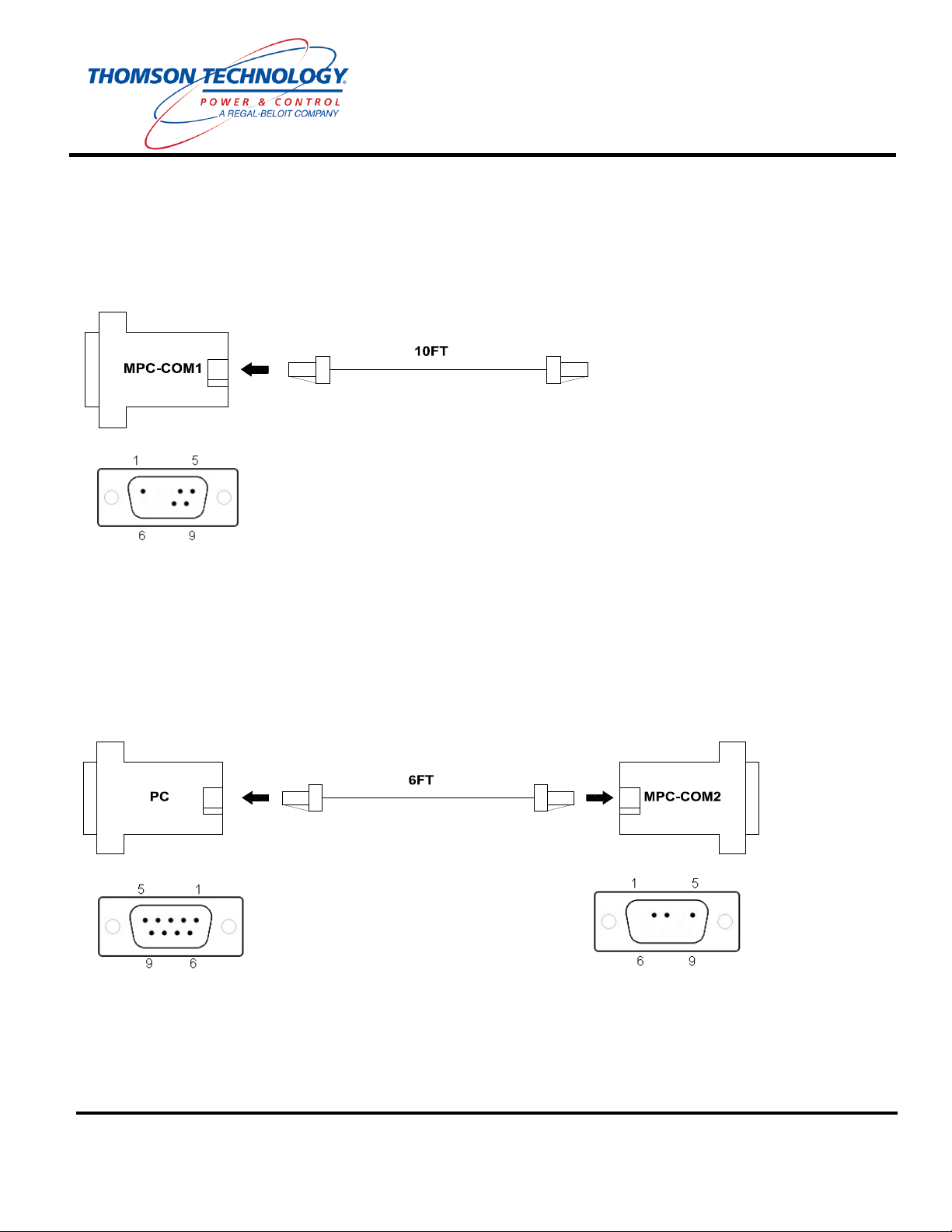
Assemble Cables:
Cable 1: Insert one end of the 10ft Ethernet cable into the connector labeled MPC-COM1
(RS485).
Programming Cable: Insert one end of the 6ft Ethernet cable into the connector labeled MPC-
COM2 (RS232). Insert the other end of the 6ft Ethernet cable into the connector labeled PC.
TELEPHONE: (604) 888-3381 ● EMAIL: info@thomsontechnology.com ● www.thomsontechnology.com
PM085 REV 1 08/08/28
THOMSON TECHNOLOGY ● 9087A – 198th STREET, LANGLEY, BC CANADA V1M 3B1
Page 3
Quick Installation Guide for MPC-STD
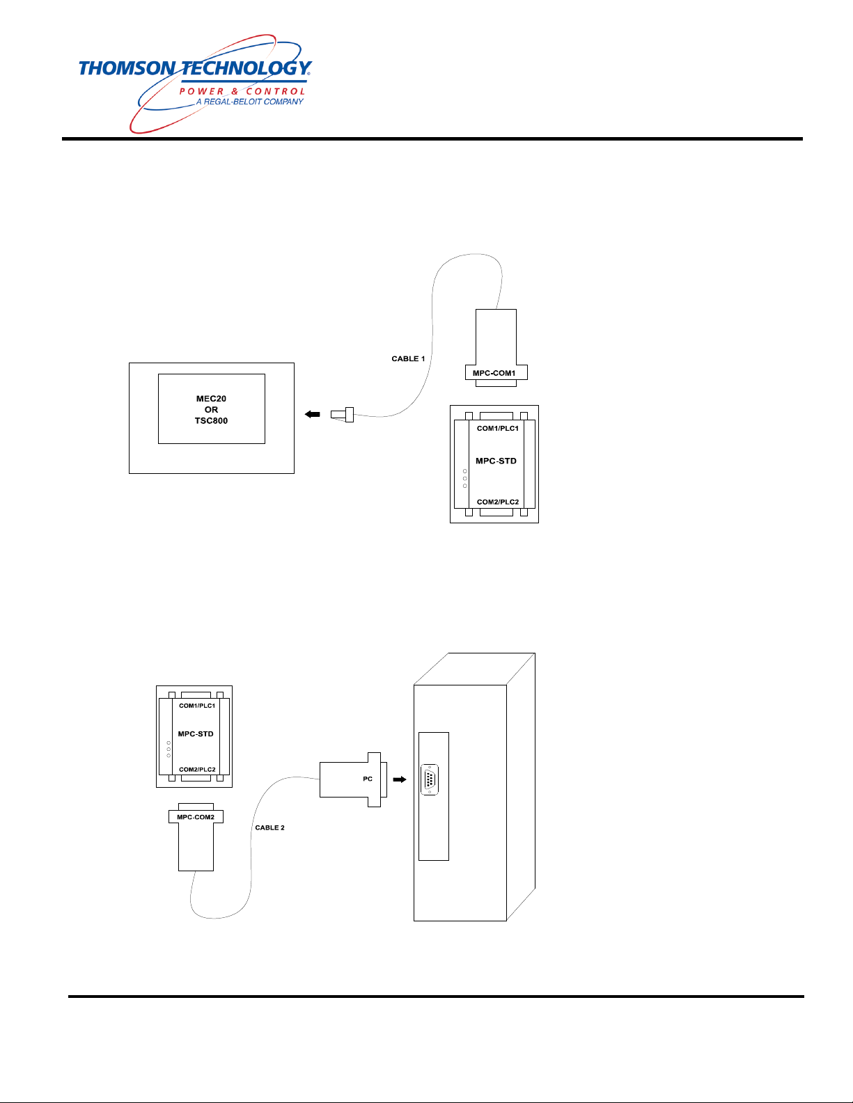
Connect MPC-STD to Controller/s:
1. Connect the RJ45 end of Cable 1 to the intended Thomson Technology controller. (i.e. MEC20
or TSC800)
2. Connect the MPC-COM1 end of Cable 1 to the MPC-STD port labeled COM1 / PLC1.
Connect MPC-STD to PC:
3. Connect the MPC-COM2 end of Cable 2 to the MPC-STD port labeled COM2 / PLC2.
4. Connect the PC end of Programming cable (Cable 2) to the serial port on the computer.
THOMSON TECHNOLOGY ● 9087A – 198th STREET, LANGLEY, BC CANADA V1M 3B1
TELEPHONE: (604) 888-3381 ● EMAIL: info@thomsontechnology.com ● www.thomsontechnology.com
PM085 REV 1 08/08/28
Page 4
Quick Installation Guide for MPC-STD
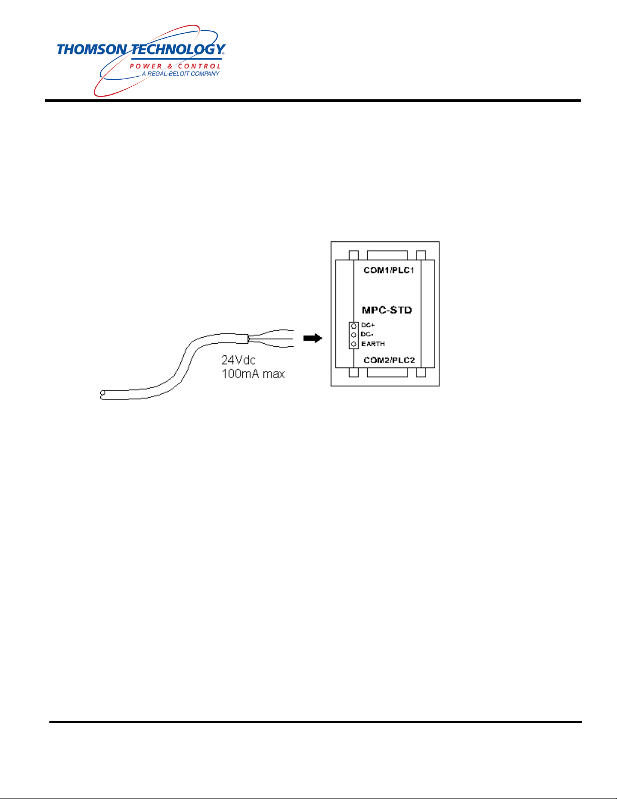
Start Up:
5. Connect 24VDC to the power input connector on the MPC-STD. Make sure that the
Protective Earth of the power supply is connected to the Earth connection of the MPC-STD.
6. Power up the MPC-STD and start Modbus™ communications with the Thomson Technology
device (i.e. MEC20 or TSC800).
7. Refer to the MPC-STD default Modbus™ map for MEC20/TSC800 parameter addresses.
TELEPHONE: (604) 888-3381 ● EMAIL: info@thomsontechnology.com ● www.thomsontechnology.com
PM085 REV 1 08/08/28
THOMSON TECHNOLOGY ● 9087A – 198th STREET, LANGLEY, BC CANADA V1M 3B1
Page 5

Installation Wizard will now
Quick Installation Guide for MPC-STD
Optional: Changing the Modbus™ node address of the MPC-STD:
1. The Gateway 3.11 Utility Software provides access to the Modbus address of the MPC-STD. Install
the software from the accompanying CD.
:\MPC SETUP KIT
311\Setup.exe
start. Press the NEXT
button to continue.
PM085 REV 1 08/08/28
TELEPHONE: (604) 888-3381 ● EMAIL: info@thomsontechnology.com ● www.thomsontechnology.com
THOMSON TECHNOLOGY ● 9087A – 198th STREET, LANGLEY, BC CANADA V1M 3B1
Page 6

Quick Installation Guide for MPC-STD
Enter desired ‘User Name’
and ‘Company Name’, and
then Press the NEXT
button.
Select desired ‘Destination
Folder’, then Press NEXT
button.
TELEPHONE: (604) 888-3381 ● EMAIL: info@thomsontechnology.com ● www.thomsontechnology.com
PM085 REV 1 08/08/28
THOMSON TECHNOLOGY ● 9087A – 198th STREET, LANGLEY, BC CANADA V1M 3B1
Page 7

Quick Installation Guide for MPC-STD
Press the NEXT button.
Mark both ‘MPC-ETN’ and
‘MPC-STD’ with a ‘check
mark’, and then Press the
NEXT button.
TELEPHONE: (604) 888-3381 ● EMAIL: info@thomsontechnology.com ● www.thomsontechnology.com
PM085 REV 1 08/08/28
THOMSON TECHNOLOGY ● 9087A – 198th STREET, LANGLEY, BC CANADA V1M 3B1
Page 8

button.
Quick Installation Guide for MPC-STD
Program is now installing
onto your computer.
Gateway 3.11 Utility Software is now Complete.
2. Run the Gateway Utility Software.
3. Ensure that the MPC-STD is powered off and then jumper pins 3 & 4 of COM2 / PLC2, (paperclip
jumper will work).
4. Power up the MPC-STD. After one second the green OK light will start blinking steadily. Remove
the jumper from pins 3 & 4.
5. Connect the COM2 end of Programming cable to the serial port on the computer.
6. Open the required template project (MEC20 or TSC800) using the Project->Open Project menu.
Wait for installation to
complete, then Press OK
Select ‘MPC-STD’ found in
the ‘Product Selection’ tree.
TELEPHONE: (604) 888-3381 ● EMAIL: info@thomsontechnology.com ● www.thomsontechnology.com
PM085 REV 1 08/08/28
Click the ‘Open Project’
button found in the Tool Bar
located at the bottom of the
THOMSON TECHNOLOGY ● 9087A – 198th STREET, LANGLEY, BC CANADA V1M 3B1
‘Gateway’ software window.
Page 9

R2.prj for TSC800
Node number (the default node
Quick Installation Guide for MPC-STD
7. To change the default Modbus node.
Select S5MEC20-R1.prj for
MEC20 communication or
S10TSC800communication, and then
Press the OPEN button.
Press the PLC2 button on the
Gateway Utility Software
toolbar.
Amend the communication
parameters to match the
communication partner setting.
Click the Advanced button to
open the Modbus node edit
dialog box.
PM085 REV 1 08/08/28
TELEPHONE: (604) 888-3381 ● EMAIL: info@thomsontechnology.com ● www.thomsontechnology.com
Enter the required Modbus
is 1).
THOMSON TECHNOLOGY ● 9087A – 198th STREET, LANGLEY, BC CANADA V1M 3B1
Page 10

port from the combo dropdown
while with a wire jumper from
r 2 to put
Quick Installation Guide for MPC-STD
8. Press the Download button of the Gateway Utility Software toolbar.
Select the appropriate COM
list. The green OK should be
blinking steadily. This
indicates that the MPC-STD is
in upload/download mode. If
the light stops blinking before
an upload or a download is
conducted then the power to
the MPC-STD must be cycled
pins 3 & 4 on COM1 o
it back into upload/download
mode.
Click the Select All button then
Download.
9. Once download is complete a confirmation will appear. Click OK to re-start the Gateway.
10. Set-up complete.
PM085 REV 1 08/08/28
TELEPHONE: (604) 888-3381 ● EMAIL: info@thomsontechnology.com ● www.thomsontechnology.com
THOMSON TECHNOLOGY ● 9087A – 198th STREET, LANGLEY, BC CANADA V1M 3B1
Page 11

Quick Installation Guide for MPC-STD
Check/Verify Communication to MPC-STD device:
1. Open ‘Modscan32.exe’ and follow the procedure below:
Select ‘Connect’ for the
‘Connection’ drop down menu.
Amend the ‘Configuration’
parameters to match the
communication partner setting
previously setup using the
Gateway 3.11 Utility Software.
I.E.
Baud Rate: 9600
Word Length: 8
Parity: EVEN
Stop Bits: 1
THOMSON TECHNOLOGY ● 9087A – 198th STREET, LANGLEY, BC CANADA V1M 3B1
PM085 REV 1 08/08/28
TELEPHONE: (604) 888-3381 ● EMAIL: info@thomsontechnology.com ● www.thomsontechnology.com
Page 12

Node number (the default node
Quick Installation Guide for MPC-STD
For MEC20 – Enter
Address: ‘1001’
Length: ‘5’
’03:HOLDING REGISTER’
For TSC800 – Enter
Address: ‘6001’
Length: ‘5’
’03:HOLDING REGISTER’
Enter the required Modbus
is 1).
I.E.
Device Id: 1
NOTE:
• When comm./setup/configuration is correct the program will increment both counters
(Number of Polls and Valid Slave Responses) at the same rate. You may notice that the
two numbers are at a different value but both will count up at the same time.
• If there is any issues with comm./setup/configuration, you may see the following messages
PM085 REV 1 08/08/28
TELEPHONE: (604) 888-3381 ● EMAIL: info@thomsontechnology.com ● www.thomsontechnology.com
o **Data Un-Initialized**
o **Device NOT CONNECTED!**
o **MODBUS Message TIME-OUT**
o **MODBUS Exception Response from Slave Device**
THOMSON TECHNOLOGY ● 9087A – 198th STREET, LANGLEY, BC CANADA V1M 3B1
 Loading...