

Page 1
Ethernet
WLAN
USB
DSL
Power
Internet
Voice
Power
Ethernet
WLAN
Plug-in
ISDN
Internet
DSL
Thomson Gateway
Wireless Configuration Guide
Page 2

Page 3

Thomson Gateway
Wireless Configuration Guide
Page 4

Copyright
Copyright ©1999-2007 THOMSON. All rights reserved.
Distribution and copying of this document, use and communication of its contents is not permitted without written authorization
from THOMSON. The content of this document is furnished for informational use only, may be subject to change without notice,
and should not be construed as a commitment by THOMSON. THOMSON assumes no responsibility or liability for any errors or
inaccuracies that may appear in this document.
Thomson Telecom Belgium
Prins Boudewijnlaan, 47
B-2650 Edegem
Belgium
http://www.thomson-broadband.com
Trademarks
The following trademarks are used in this document:
> DECT is a trademark of ETSI.
> Bluetooth® word mark and logos are owned by the Bluetooth SIG, Inc.
> Ethernet™ is a trademark of Xerox Corporation.
> Wi-Fi® and the Wi-Fi logo are registered trademarks of the Wi-Fi Alliance. "Wi-Fi CERTIFIED", "Wi-Fi ZONE", "Wi-Fi Alli-
ance", their respective logos and "Wi-Fi Protected Access" are trademarks of the Wi-Fi Alliance.
> UPnP™ is a certification mark of the UPnP™ Implementers Corporation.
> Microsoft®, MS-DOS®, Windows® and Windows NT® are either registered trademarks or trademarks of Microsoft Corpo-
ration in the United States and/or other countries.
> Apple® and Mac OS® are registered trademarks of Apple Computer, Incorporated, registered in the United States and
other countries.
> UNIX® is a registered trademark of UNIX System Laboratories, Incorporated.
> Adobe®, the Adobe logo, Acrobat and Acrobat Reader are trademarks or registered trademarks of Adobe Systems, Incor-
porated, registered in the United States and/or other countries.
Other brands and product names may be trademarks or registered trademarks of their respective holders.
Document Information
Status: v2.0 (April 2007)
Reference: E-DOC-CTC-20060609-0001
Short Title: Config Guide: WLAN R6.2 (and higher)
Page 5

E-DOC-CTC-20060609-0001 v2.0
i
Contents
About this Wireless Configuration Guide ................................ 1
1 Introducing Wireless Networking .............................................. 3
1.1 Introduction .................................................................................................... 3
1.2 WLAN Components and Terminology ............................................................. 5
2 802.11 Standards ....................................................................... 11
2.1 MAC Sublayer ............................................................................................... 13
2.2 802.11a ......................................................................................................... 16
2.3 802.11b ......................................................................................................... 19
2.4 802.11g ......................................................................................................... 22
3 Security....................................................................................... 25
3.1 Disabling SSID Broadcasting ........................................................................ 27
3.2 MAC Address Filtering .................................................................................. 28
3.3 Wired Equivalent Privacy (WEP) .................................................................... 29
3.4 Wi-Fi Protected Access (WPA)....................................................................... 31
3.5 WPA2 ............................................................................................................ 35
4 Wi-Fi Multi Media (WMM)......................................................... 37
5 Wireless Distribution System (WDS)....................................... 39
6 Virtual Access Points................................................................. 41
6.1 What is a Virtual Access Point? .................................................................... 42
6.2 Multiple SSIDs .............................................................................................. 44
6.3 Architectural Elements ................................................................................. 46
7 Thomson Gateway Wireless Configuration ............................ 47
Page 6

E-DOC-CTC-20060609-0001 v2.0
Contents
ii
7.1 Basic Configuration ...................................................................................... 48
7.1.1 Connecting Wireless Stations for the First Time ............................................................................... 49
7.1.2 Configuring Wireless Stations.............................................................................................................51
7.1.3 Configuring the Thomson Gateway Access Point ............................................................................. 54
7.1.4 Connecting Additional Wireless Stations...........................................................................................61
7.1.5 Configuring your Thomson Gateway with WDS ...............................................................................63
7.1.6 Reset to Factory Defaults .....................................................................................................................65
7.2 Expert Configuration..................................................................................... 67
7.2.1 Access Point Settings...........................................................................................................................69
7.2.2 Security .................................................................................................................................................72
7.2.3 Associated Stations..............................................................................................................................77
7.2.4 Networks ...............................................................................................................................................78
Page 7

E-DOC-CTC-20060609-0001 v2.0
1
About this Wireless Configuration Guide
About this Wireless Configuration Guide
Used symbols
Typographical conventions
Following typographical convention is used throughout this manual:
> Sample text indicates a hyperlink to a Web site.
Example: For more information, visit us at www.thomson-broadband.com
.
> Sample text indicates an internal cross-reference.
Example: If you want to know more about guide, see “1 Introduction” on page 7”.
> Sample text indicates an important content-related word.
Example: To enter the network, you must authenticate yourself.
> Sample text indicates a GUI element (commands on menus and buttons, dialog box elements, file
names, paths and folders).
Example: On the File menu, click Open to open a file.
> Sample text indicates a CLI command to be input after the CLI prompt.
Example: To obtain a list of all available command groups, type
help at the top level.
> Sample text indicates input in the CLI interface.
> Sample text indicates comment explaining output in the CLI interface.
Example:
Documentation and software updates
THOMSON continuously develops new solutions, but is also committed to improving its existing products.
For suggestions regarding this document, please contact documentation.speedtouch@thomson.net
.
For more information on THOMSON's latest technological innovations, documents and software releases,
visit us at http://www.thomson-broadband.com
.
i
A note provides additional information about a topic.
!
A caution warns you about potential problems or specific precautions that need to be taken.
=> language list
CODE LANGUAGE VERSION FILENAME
en* english 4.2.0.1 <system>
Only one language is available
Output
Input
Comments
Page 8

E-DOC-CTC-20060609-0001 v2.0
2
About this Wireless Configuration Guide
Page 9

E-DOC-CTC-20060609-0001 v2.0
Chapter 1
Introducing Wireless Networking
3
1 Introducing Wireless Networking
1.1 Introduction
IEEE 802.11
In the early ‘90s a lot of wireless systems were developed because people wanted to connect their laptop
computers to the network (and Internet) when entering the office. The problem was that none of these
systems was compatible with the other. Finally, the IEEE association elaborated a standard for Wireless Local
Area Networks (WLAN). This standard was referred to as 802.11 or Wi-Fi (Wireless Fidelity). As Ethernet had
become the actual standard for LAN, the WLAN standard was designed to be compatible with Ethernet above
the data link layer. As a result, IP packets can be sent over a WLAN in the same way that they are sent over
Ethernet.
Overview of wireless standards
This is an extensive alphabetical list of existing popular wireless standards:
> AMPS: Advanced Mobile Phone System. AMPS is the first analog cellular standard in the U.S. Although
AMPS is still in use, it is anticipated to be replaced by the United States Digital Cellular (USDC) standard.
> Bluetooth: Bluetooth is an industrial specification for Wireless Personal Area Networks (WPANs).
Bluetooth provides a way to connect and exchange information between devices such as mobile phones,
laptops, PCs, printers, digital cameras and video game consoles via a secure, globally unlicensed shortrange radio frequency. IEEE 802.15.1 has derived a WPAN standard based on the Bluetooth v1.1
specifications. It includes a medium access control and physical layer specification.
> CDPD: Cellular Digital Packet Data is a digital standard for packet data services. CDPD was designed to
overlay with existing cellular infrastructure, thereby permitting simple and inexpensive installation.
> CEBus: The Consumer Electronics Bus (CEBus) standard was created by the Electronic Industries
Association (EIA). CEBus is an engineering standard for home automation products. It supports carrier
current, RF, IR, coaxial cable, twisted pair, and fibre optic cable.
> DECT: Digital Enhanced (formerly European) Cordless Telecommunications is a universal cordless
telephone standard developed by the European Telecommunications Standard Institute (ETSI). DECT
offers services for both voice and data communications.
> GSM: Global System for Mobile Communications. The GSM standard was developed in Europe to
standardize cellular communications among European countries. GSM has proven to be one of the most
successful standards of the last decades and continues as one of the world`s most popular standards for
new cellular radio and personal communications equipment.
> HIPERLAN: HIgh PErformance Radio LAN is a WLAN standard. It is a European alternative for the
IEEE 802.11 standards. It is defined by ETSI. In ETSI, the standards are defined by the BRAN (Broadband
Radio Access Networks) project.
> IEEE 802.11 a,b,g: This is the IEEE standard for WLANs. The goal of the IEEE 802.11 committee is to
standardize WLAN development in the ISM (Industrial, Scientific and Medical) band. The standard
focuses on the Media Access Control (MAC) and the physical (PHY) protocol levels. The IEEE 802.11
standard is still under development, but is anticipated to become the WLAN standard.
> IrDA: The Infrared Data Association (IrDA) was formed to develop a standard for wireless communication
using infrared (IR) technology. Some of the main goals of the committee are to develop a standard that
permits low cost, low power, point-to-point user communications using IR as the transmission medium.
> IS-54: Interim Standard 54. See USDC.
Page 10

E-DOC-CTC-20060609-0001 v2.0
Chapter 1
Introducing Wireless Networking
4
> IS-95: IS-95 is a digital cellular standard from the United States that uses a Code Division Multiple Access
(CDMA) scheme. In a CDMA system, users share time and frequency resources simultaneously. This
occurs through assigning a distinct digital code to each user. This code is added to the information data
and modulated onto the carrier, using spread spectrum techniques. Although it anticipates providing
significant capacity improvement and increased interference rejection over other digital cellular
standards, IS-95 remains somewhat controversial because of its wide bandwidth requirements.
> PHS: The Personal Handphone System standard was developed in Japan specifically for indoor and
microcell usage.
> UMTS: Universal Mobile Telecommunications System. UMTS is one of the third-generation (3G) mobile
phone technologies. The currently most common form uses W-CDMA as the underlying air interface and
is standardized by the 3GPP. UMTS is the European answer to the ITU IMT-2000 requirements for 3G
cellular radio systems and was designed to succeed GSM.
> USDC: United States Digital Cellular, also known as IS-54 (Interim Standard 54), was developed to replace
the AMPS standard, particularly in urban areas where AMPS did not provide adequate channel capacity.
USDC allows the co-existence of AMPS so that providers can gradually phase out AMPS as needed.
> WiMAX: WiMAX is a wireless industry coalition whose members organized to advance IEEE 802.16
standards for broadband wireless access (BWA) networks. WiMAX 802.16 technology is expected to
enable multimedia applications with wireless connection and, with a range of up to 30 miles, enable
networks to have a wireless last mile solution.
Wi-Fi
The Wi-Fi Alliance is a global, non-profit organization that is responsible for testing and certifying
interoperability of wireless devices.
The Wi-Fi Alliance controls the Wi-Fi Certified logo which is permitted only on compliant equipment,
indicating that the device is interoperable with any other product also showing the logo. The following
illustration shows the Wi-Fi certified logo.
Page 11

E-DOC-CTC-20060609-0001 v2.0
Chapter 1
Introducing Wireless Networking
5
1.2 WLAN Components and Terminology
Access point
A WLAN base station or Access Point (AP) behaves as a networking hub, allowing to interconnect several
devices wirelessly to the local WLAN.
WLAN topologies
A WLAN consists of several devices. The logical grouping of devices belonging to a particular WLAN is called
a service set. Depending on the architecture, the following topologies can be determined:
> Independent Basic Service Set (IBSS) or ad-hoc network
> Basic Service Set (BSS) or infrastructure network
> Extended Service Set (ESS)
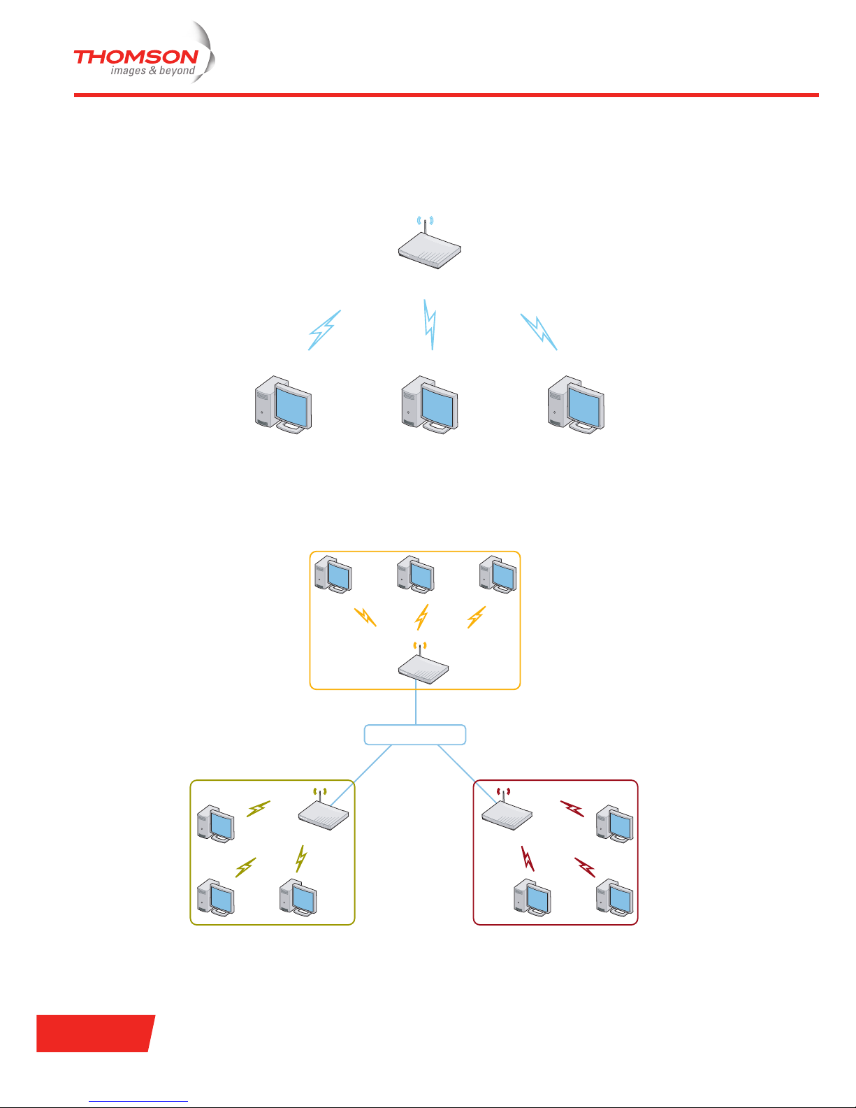
Independent Basic Service Set (IBSS) or ad-hoc network
This is a peer-to-peer WLAN, because wireless stations communicate directly with one another.
Communication does not happen via an AP. Wireless stations communicate with each other via 802.11
Network Interface Cards (NIC). This kind of WLAN is usually small and very temporary (usually they last until
the sharing of information is accomplished). The following example illustrates an IBSS:
Page 12
E-DOC-CTC-20060609-0001 v2.0
Chapter 1
Introducing Wireless Networking
6
Basic Service Set (BSS) or infrastructure network
This WLAN topology requires a specialized station, called an AP. Wireless stations do not communicate
directly with one another, but all communication is passed to the destination via this central AP. APs can be
connected to a wired network via an uplink port. The following example illustrates a BSS:
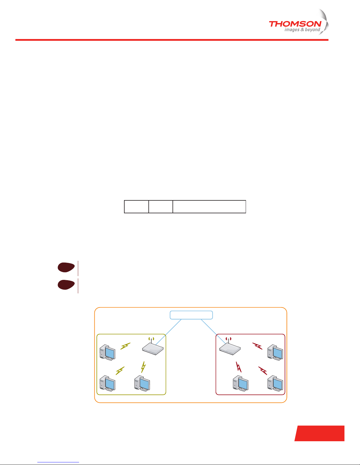
Extended Service Set (ESS)
When several BSSs are connected to each other via a Distribution System (very often an Ethernet switch),
the WLAN is called an ESS. The distribution system can be either wired or wireless. The following
example illustrates an ESS:
Wireless Access Point
Wireless Stations
Distribution System
BSS2BSS1
BSS3
Page 13
E-DOC-CTC-20060609-0001 v2.0
Chapter 1
Introducing Wireless Networking
7
Basic Service Set Identifier (BSSID)
The Basic Service Set Identifier (BSSID) uniquely identifies each BSS. The BSSID is a 48-bit address with the
same format as an IEEE 802 MAC address. The value of all 1s is used to indicate the broadcast BSSID.
The station that starts the BSS determines the BSSID of that BSS, depending on the topology:
> In case of an ad-hoc network, the BSSID is determined by the use of a 46-bit random number generator.
The used mechanism provides a high probability of selecting a unique BSSID.
> In case of an infrastructure network, the BSSID is the same as the MAC address of the AP. All wireless
stations communicating to the AP send to the BSSID.
Service Set Identifier (SSID) or Network Name
Wireless stations communicate with each other through the air, which is a shared medium. As no physical
connection exists between the APs and the wireless stations, a name must be given to allow unique
identification of your WLAN. This is called the Service Set Identifier (SSID) or Network Name. Wireless
stations must be part of a specific SSID environment in order to communicate with the other stations
belonging to the same WLAN.
The SSID has a length between 0 and 32 octets. A length equal to 0 octets indicates the broadcast SSID. This
SSID is included in the SSID Information Element (IE), which is part of management frames such as beacon
frames, probe request/response frames and association/reassociation request frames. The following
illustration depicts the format of the SSID IE:
Two types of SSIDs are defined, depending on the topology:
> In case of an ad-hoc network, the SSID is also called the Independent Basic Service Set Identifier (IBSS
ID).
> In case of an infrastructure network, the term Basic Service Set Identifier (BSS ID) or Extended Service
Set Identifier (ESS ID) can be used instead of SSID.
The following example illustrates the use of the BSSID and SSID:
i
In many cases both types of SSID are referred to as SSID or Network Name.
!
The use of the term Basic Service Set Identifier can cause confusion with the BSSID defined as the
MAC address of the AP.
Element
ID
1 byte 1 byte 0-32 bytes
Length SSID
Distribution System
BSS2
ESS
BSS1
BSSID1
BSSID2
SSID
SSID
Page 14

E-DOC-CTC-20060609-0001 v2.0
Chapter 1
Introducing Wireless Networking
8
Beacon frame
Beacon frames are transmitted periodically by APs to let wireless stations identify the wireless APs nearby.
They inform the wireless stations in the BSSs (and thus a possible ESS) about the existence of a wireless
network.
Beacon frames are transmitted on all channels (in the regulatory allowed spectrum) and contain among other
things the BSSID, the SSID and a set of capabilities, e.g. the supported data rate, the supported security
mechanism,...
Standards overview
The 802.11 standard defines a set of different physical layer technologies to be used in combination with
802.11 MAC. The standard has evolved over the years. The different technologies primarily vary in frequency
bands and applied modulation techniques (resulting in different transmission rates). A short overview:
> 802.11
The first standard was released in 1997. It operated at a data transmission rate of 1 or 2 Mbps, which was
much too slow for most applications, and was transmitted at 2.4 GHz.
This standard is now often referred to as 802.11 legacy.
> 802.11b
This standard was ratified in 1999. It uses the same frequency band as the original 802.11, but uses a
different modulation technique, so that a transmission rate of 11 Mbps is achieved.
> 802.11a
At the same time that 802.11b was ratified, 802.11a was ratified.This standard uses the 5 GHz band and
has a data transmission rate up to 54 Mbps.
> 802.11g
This standard was ratified in 2003. 802.11g is backward compatible with 802.11b and also operates in the
2.4 GHz band. Because of the use of a different modulation technique, data transmission rate can go up to
54 Mbps.
For further details on each of these standards, please refer to “2 802.11 Standards” on page 11.
The following list contains an exhaustive overview of all existing 802.11 standards:
Standard Description
802.11 Wireless LAN Medium Access Control (MAC) and Physical Layer (PHY) Specifications: the
original 1 Mbps and 2 Mbps, 2.4 GHz RF and IR standard (1997).
802.11a High-speed Physical Layer in the 5 GHz band: 54 Mbps, 5 GHz standard (1999).
802.11b Higher speed Physical Layer extension in the 2.4 GHz band: enhancements to 802.11 to
support 5.5 and 11 Mbps (1999).
802.11c Bridge operation procedures; included in the IEEE 802.1D standard (2001).
802.11d Specification for Operation in Additional Regulatory Domains (2001).
802.11e Enhancements: QoS, including packet bursting (2005).
802.11F Recommended Practice for Multi-Vendor Access Point Interoperability via an Inter-Access
Point Protocol Across Distribution Systems Supporting IEEE 802.11 (2003). Withdrawn in
February 2006.
Page 15

E-DOC-CTC-20060609-0001 v2.0
Chapter 1
Introducing Wireless Networking
9
ISM band
WLANs operate in the ISM band. The Industrial, Scientific and Medical (ISM) radio bands were originally
reserved internationally for non-commercial use of RF electromagnetic fields for industrial, scientific and
medical purposes.
The ISM bands are defined by the ITU-R in 5.138 and 5.150 of the Radio Regulations. The channels and their
allocations are governed by regulatory bodies and can differ due to variations in national radio regulations.
However, many countries have similar spectrum regulations. The ETSI has the regulatory control over the
wireless spectrum in Europe, the Federal Communications Commission (FCC) in the United States, the
MPHPT in Japan.
Radiocommunication services operating within these bands must accept harmful interference, which may be
caused by these applications.
The different ISM bands are:
> 900 MHz band (902 - 928 MHz)
> 2.4 GHz band (2.4 - 2.5 GHz)
> 5.8 GHz band (5.725 - 5.875 GHz)
> 24 GHz band (24 - 24.25 GHz)
802.11g Further Higher-Speed Physical Layer Extension in the 2.4 GHz Band: 54 Mbps, 2.4 GHz
standard (backwards compatible with b) (2003).
802.11h Spectrum and Transmit Power Management Extensions in the 5 GHz band in Europe:
Spectrum Managed 802.11a for European compatibility (2004).
802.11i Medium Access Control (MAC) Security Enhancements: enhanced security (2004).
802.11j 4.9 GHz–5 GHz Operation in Japan: extensions for Japan (2004).
802.11k Radio resource measurement enhancements.
802.11m Maintenance of the standard.
802.11n Higher throughput improvements: aims for a data transmission rate of 540 Mbps.
802.11p WAVE - Wireless Access for the Vehicular Environment: to support Intelligent
Transportation Systems (ITS) applications.
802.11r Fast BSS transitions.
802.11s ESS Mesh Networking.
802.11T Wireless Performance Prediction (WPP) - test methods and metrics.
802.11u Interworking with non-802 networks (for example cellular).
802.11v Wireless network management.
802.11w Protected Management Frames.
802.11y Contention Based Protocol: defines 3.65 - 3.7 GHz operation in USA.
i
Not all standards are ratified yet.
Standard Description
Page 16

E-DOC-CTC-20060609-0001 v2.0
Chapter 1
Introducing Wireless Networking
10
IEEE 802.11b/g wireless Ethernet operates on the 2.4 GHz band, IEEE 802.11a operates on the 5 GHz band.
The following illustration shows the different ISM bands.
U-NII band
U-NII stands for the Unlicensed National Information Infrastructure. The FCC has made 300 MHz of spectrum
available for U-NII devices that will provide short-range, high speed wireless digital communications. The UNII band includes following bands:
> U-NII 1 band or U-NII indoor (5.15 - 5.25 GHz)
> U-NII 2 band or U-NII low (5.25 - 5.35 GHz)
> U-NII 3 band or U-NII ISM ((5.725 - 5.825 GHz)
What is antenna diversity?
Antenna diversity is a function included in most WLAN equipment that has two antennas.
In simple terms, diversity monitors the signal from each antenna and automatically switches to the one with
the better signal. The user usually has no control over this function.
Use of directional antennas
The wireless coverage area should be fit to the desired area. Directional antennas can be used at the
perimeter directing their broadcasting inward. Some APs offer attenuation levels to be set via their webbased setup utility.
902-928
2400-2500
5725-5875
24000-24125
f (MHz)
5,15-5,25
5.725-5.825
5.25-5,35
f (MHz)
Page 17

E-DOC-CTC-20060609-0001 v2.0
Chapter 2
802.11 Standards
11
2 802.11 Standards
802.11 protocol stack
The 802.11 protocol stack is very similar to the other 802 variants (such as Ethernet). The physical layer
corresponds to the OSI physical layer and the data link layer is split into two sublayers:
> The MAC sublayer determines how the channel is allocated.
> The LLC sublayer interfaces the different 802 variants to the network layer.
The 802.11 protocol defines a number of standards which differ on the physical layer level. Depending on the
transmission technique, the following standards are defined in the 802.11 protocol stack:
History
The 1997 802.11 standard specifies a single MAC sublayer that interacts with three transmission techniques:
> Infrared
> Frequency Hopping Spread Spectrum (FHSS)
> Direct Sequence Spread Spectrum (DSSS)
These transmission techniques operate at 1 or 2 Mbps and with low power.
FHSS and DSSS use the 2.4 GHz ISM band. Both techniques are also referred to as 802.11 legacy.
All of the three standards are now outdated and replaced.
To achieve higher bandwidth two new techniques were introduced in 1999:
> Orthogonal Frequency Division Multiplexing (OFDM), used in the 802.11a standard, operating at up to
54 Mbps.
> High-Rate DSSS (HR-DSSS), used in the 802.11b standard, operating at up to 11 Mbps.
In 2001 an enhanced version of the 802.11b, namely 802.11g, was released. It also operates at up to 54 Mbps,
applying OFDM. 802.11g is backward compatible with 802.11b.
Upper Layers
Data Link Layer
Physical Layer
MAC Sublayer
802.11g
OFDM
802.11b
HR-DSSS
802.11a
OFDM
802.11
DSSS
802.11
FHSS
802.11
Infrared
Logical Link Control
Page 18

E-DOC-CTC-20060609-0001 v2.0
Chapter 2
802.11 Standards
12
Overview
The MAC sublayer and the three contemporary transmission techniques are described in the following
chapter:
Topi c Page
“2.1 MAC Sublayer” 13
“2.2 802.11a” 16
“2.3 802.11b” 19
“2.4 802.11g” 22
Page 19

E-DOC-CTC-20060609-0001 v2.0
Chapter 2
802.11 Standards
13
2.1 MAC Sublayer
MAC architecture
The MAC architecture uses the following two access methods:
> Distributed Coordination Function (DCF): this is the fundamental access method of the MAC sublayer.
The DCF is also known as Carrier Sense Multiple Access with Collision Avoidance (CSMA/CA). This
access method is implemented in all wireless stations, for use within both ad-hoc network and
infrastructure network configurations.
> Point Coordination Function (PCF): this is an optional access method of the MAC sublayer. The PCF can
only be used within infrastructure network configurations. This access method uses a point coordinator
(PC), which operates at the AP of the BSS, to determine which station has the right to transmit at a given
time.
The DCF and the PCF can coexist in a way that allows both to operate simultaneously within the same BSS.
When a PC is operating in a BSS, the two access methods alternate.
Carrier Sense Multiple Access (CSMA)
CSMA is a listen before talk mechanism. A wireless station that wants to transmit a frame must first sense the
medium. The wireless station senses the medium using two mechanisms:
> A physical carrier sense mechanism: this mechanism is provided by the physical layer. A station can
check the physical layer and detect whether the medium is in use. The wireless medium is in use if
another station is transmitting.
> A virtual carrier sense mechanism: this mechanism is provided by the MAC sublayer. Even if none of the
stations is transmitting, the medium might still be reserved by a station via the Network Allocation Vector
(NAV). The NAV of a station gives a prediction of future transmissions on the medium. It is based on the
duration information in the 802.11 frames. The NAV is a timer that is decremented at a uniform rate. A
station will not try to transmit until the NAV has decremented to 0.
If one of the mechanisms indicates that the medium is in use, then a station must postpone its transmission.
If the medium is not in use, then a station is allowed to transmit.
Page 20
E-DOC-CTC-20060609-0001 v2.0
Chapter 2
802.11 Standards
14
Distributed Coordination Function (DCF)
The following components are important to understand the operation of the DCF:
> Interframe space: in the DCF, a wireless station that wants to transmit a data frame must wait a specific
amount of time after the station senses that the medium is not in use. This amount of time is known as
the DCF Interframe Space (DIFS).
> Random backoff algorithm: several stations will sense at the same time that the medium is not in use. As
a result, there is a high probability that several stations will try to transmit simultaneously, causing a
collision. To avoid this situation, DCF uses a random backoff algorithm.
> Positive acknowledgements: a station acknowledges the correct receipt of a data frame by sending an
acknowledgement frame back to the sending station. The receiving station is allowed to skip the random
backoff algorithm and waits only a short interval before transmitting the acknowledgement frame. The
short interval is known as the Short Interframe Space (SIFS).
The exchange of a data frame (Data) and an acknowledgement frame (ACK) between sender and receiver is
illustrated in the following figure:
Interframe space (IFS)
The time interval between frames is called the Interframe Space (IFS). Different IFSs are defined to provide
priority levels for accessing the wireless medium:
> Short Interframe Space (SIFS): this is the shortest of the interframe spaces. A SIFS is used to separate
transmissions belonging to a single dialogue, e.g. between a data frame and an acknowledgement frame.
> Distributed Interframe Space (DIFS): this is used by a station that wants to start a new transmission.
> Extended Interframe Space (EIFS): this is used by a station that has received a frame that it could not
understand. This is needed to prevent the station from colliding with a future frame belonging to the
current dialogue.
Data
ACK
Contention Window
DIFS
SIFS
DIFS
Delay Access Backoff After Delay
Receiver
Sender
Other
Page 21

E-DOC-CTC-20060609-0001 v2.0
Chapter 2
802.11 Standards
15
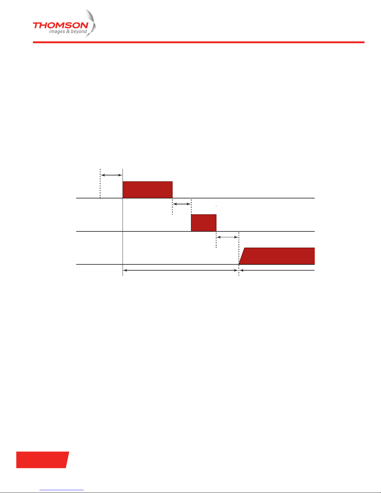
Random backoff algorithm
Backoff is a well known method to avoid collisions between several stations that want to access the medium.
Each station must select a random number between 0 and a given value, called the Contention Window (CW).
This random number is the number of 802.11 slot times that the station must wait before it is allowed to
transmit. The station always checks whether another station has accessed the medium at the beginning of
the previous slot.
Each time the station decides to transmit and a collision occurs, it increases the value of the CW. The value of
the CW is a moving ceiling starting at CW
min
and stopping at a maximum value known as CW
max
. The
following figure illustrates the CW
min
and CW
max
values for binary random backoff:
The random backoff algorithm must be executed in the following situations:
> When the station senses the medium before the first transmission of a frame and the medium is in use.
> After each retransmission.
> After a successfull transmission.
This algorithm is not used when a station decides to transmit a new frame and the medium has not been in
use for more than a DIFS.
Positive acknowledgements
The correct receipt of a data frame, requires the receiving station to respond with an ACK. This technique is
known as Positive Acknowledgement. If no ACK is received by the sending station, it assumes that an error
has occurred. If no ACK is received:
1 The sending station updates its retry counter.
2 The sending station doubles the value of the Contention Window.
3 A retransmission of the data frame is scheduled by the sender.
Initial Attempt
First Retransmission
Second Retransmission
Third Retransmission
CW
max
CW
min
255 255
7
15
31
63
127
Page 22

E-DOC-CTC-20060609-0001 v2.0
Chapter 2
802.11 Standards
16
2.2 802.11a
Technical specifications
The 802.11a standard operates in the U-NII band and applies Orthogonal Frequency Division Multiplexing
(OFDM) as modulation technique. The data transfer rate can be up to 54 Mbps, but will be scaled back to 48,
36, 24, 18, 12, 9 or 6 Mbps (this is known as Adaptive Rate Selection) when the signal quality becomes an
issue. 802.11a allows 64 users per access point.
There is no compatibility with either 802.11b or 802.11g.
U-NII band 802.11a channel allocation
The following table summarizes the 802.11a channels in the U-NII band. The assigned channels can differ
from country to country.
!
The regulatory information in this section is given for information only. This information is subject
to change by the regulatory bodies. The FCC is the regulatory body in the U.S., the ETSI is the
regulatory body in Europe.
Channel
Identifier
Centre
Frequency
(GHz)
Regulatory Domain
America ETSI Japan Tai wa n Singapore
34 5.170 - - Y - -
36 5.180 Y Y - - Y
38 5.190 - - Y - -
40 5.200 Y Y - - Y
42 5.210 - - Y - -
44 5.220 Y Y - - Y
46 5.230 - - Y - -
48 5.240 Y Y - - Y
52 5.260 Y Y - Y -
56 5.280 Y Y - Y -
60 5.300 Y Y - Y -
64 5.320 Y Y - Y -
100 5.500 - Y - - -
104 5.520 - Y - - -
108 5.540 - Y - - -
112 5.560 - Y - - -
116 5.580 - Y - - -
120 5.600 - Y - - -
124 5.620 - Y - - -
Page 23
E-DOC-CTC-20060609-0001 v2.0
Chapter 2
802.11 Standards
17
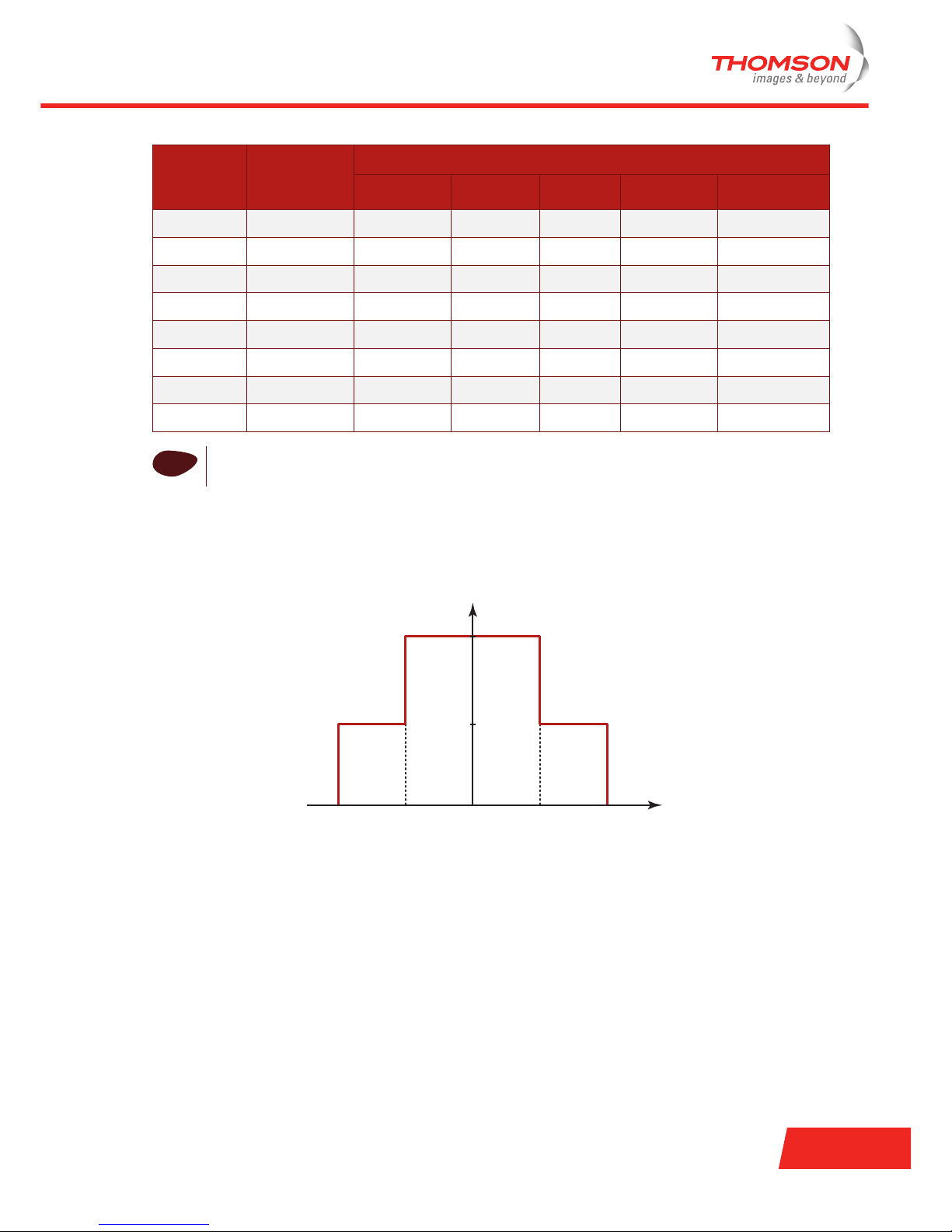
Spectral mask
The spectral mask or Power Spectral Density (PSD) mask for the 802.11a standard is shown in the following
figure:
Available channels
In the U-NII 1 and 2 bands, eight non-overlapping channels are available. Bear in mind that the centre
frequencies of the edge channels are 30 MHz from the band edge and the spacing between the centre
frequencies is 20 MHz.
In the U-NII 3 band, four non-overlapping channels are available. In contrast to the other bands, the centre
frequencies are only 20 MHz from the edge band. The spacing between the other centre frequencies remains
20 MHz.
128 5.640 - Y - - -
132 5.660 - Y - - -
136 5.680 - Y - - -
140 5.700 - Y - - -
149 5.745 - - - - -
153 5.765 - - - - -
157 5.785 - - - - -
161 5.805 - - - - -
i
Users are responsible for ensuring that the channel set configuration is in compliance with the
regulatory standards of the country they are residing.
Channel
Identifier
Centre
Frequency
(GHz)
Regulatory Domain
America ETSI Japan Tai wa n Singapore
0 dBr
f
c
-30 dBr
MHzfc+11 fc+22fc-22 fc-11
Page 24

E-DOC-CTC-20060609-0001 v2.0
Chapter 2
802.11 Standards
18
Maximum power output
The U-NII band is split into three working domains, with different power outputs allowed:
> U-NII 1 band: maximum power output of 50 mW.
> U-NII 2 band: maximum power output of 250 mW.
> U-NII 3 band: maximum power output of 1 W (esp. for outdoor applications).
The following table indicates the maximum power levels and antenna gains allowed for each IEEE 802.11a
regulatory domain:
Range
Typical indoor range is 10 m at 54 Mbps and 60 m at 6 Mbps. By using directional antennas, you can enlarge
the range of your network.
Regulatory Domain Maximum Power Level (mW) with
6 dBi Antenna Gain
America
(160 mW EIRP maximum on channels 36-48,
(800 mW EIRP maximum on channels 52-64)
40
Japan
(10 mW/MHz EIRP maximum)
40
Singapore
(100 mW EIRP maximum)
20
Ta iw an
(800 mW EIRP maximum)
40
i
The use of directional antennas is regulated country by country. Check the local regulations before
using directional antennas.
Page 25

E-DOC-CTC-20060609-0001 v2.0
Chapter 2
802.11 Standards
19
2.3 802.11b
Technical specifications
The 802.1b standard operates in the 2.4 GHz band and applies HR-DSSS with Complementary Code Keying
(CCK), or optionally Packet Binary Convolutional Coding (PBCC) as modulation technique. The data transfer
rate can be up to 11 Mbps, but will be scaled back to 5.5, 2 or 1 Mbps when the signal quality becomes an
issue. 802.11b allows 32 users per access point.
802.11b is backward compatible with 802.11 legacy.
ISM band 802.11b channel allocation
The following table summarizes the 802.11b channels in the 2.4 GHz ISM band. The assigned channels can
differ from country to country.
!
The regulatory information in this section is given for information only. This information is subject
to change by the regulatory bodies. The FCC is the regulatory body in the U.S., the ETSI is the
regulatory body in Europe.
Channel
Identifier
Centre
Frequency
(GHz)
Regulatory Domain
America EMEA
1
1. EMEA: stands for Europe, Middle East and Africa.
Japan Israel China
12.412Y Y Y - Y
2 2.417 Y Y Y - Y
32.422Y Y Y - Y
4 2.427 Y Y Y - Y
52.432Y Y Y Y Y
6 2.437 Y Y Y Y Y
72.442Y Y Y Y Y
8 2.447 Y Y Y Y Y
92.452Y Y Y - Y
10 2.457 Y Y Y - Y
11 2.462 Y Y Y - Y
12 2.467 - Y Y - -
13 2.472 - Y Y - -
14 2.484 - - Y - -
i
Users are responsible for ensuring that the channel set configuration is in compliance with the
regulatory standards of the country in which they are residing.
Page 26
E-DOC-CTC-20060609-0001 v2.0
Chapter 2
802.11 Standards
20
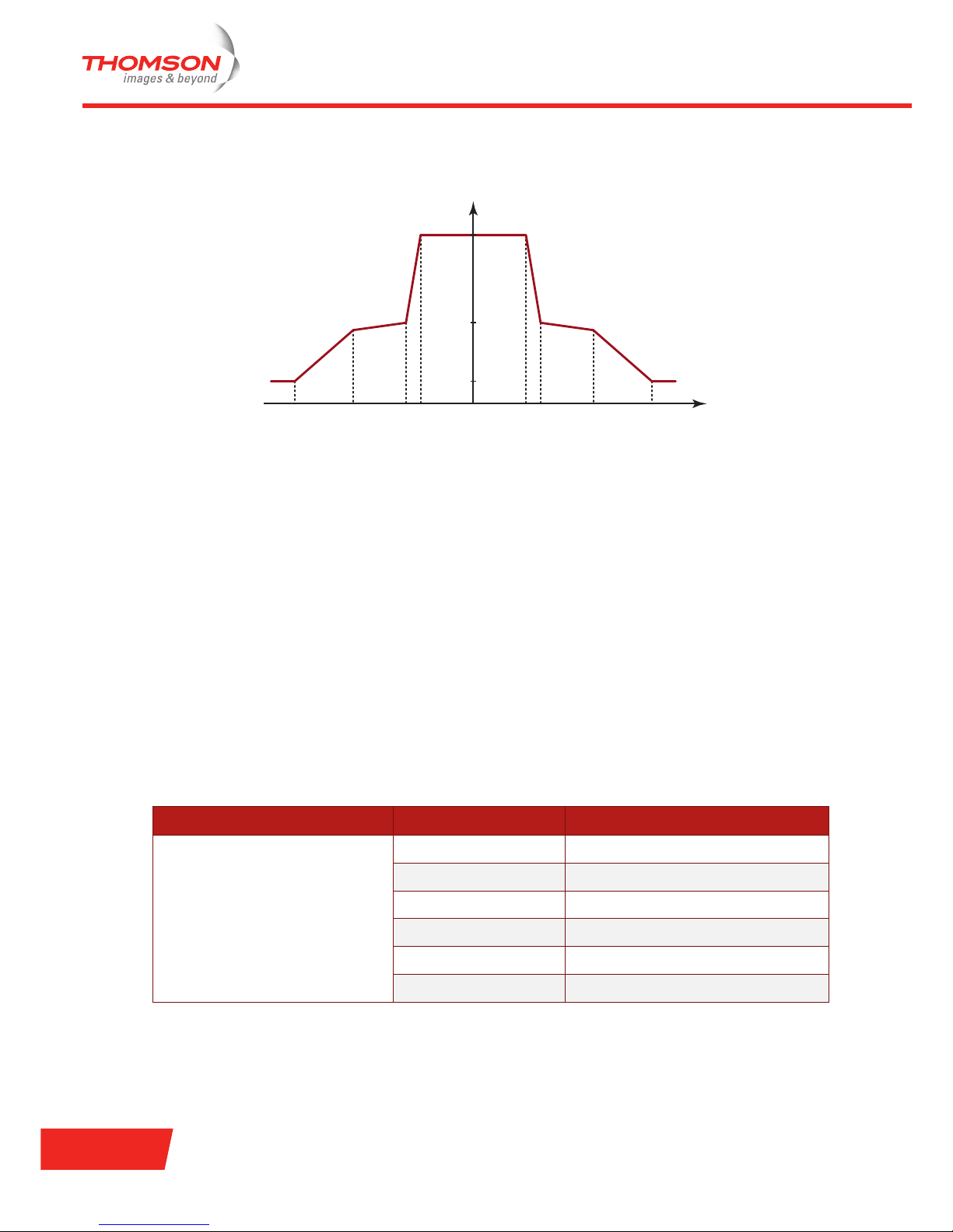
Spectral mask
The spectral mask for the 802.11b standard is shown in the following figure:
Available channels
An important concept regarding channel assignments is that the channel actually represents the centre
frequency that the transceiver within the radio and access point uses (for example 2.412 GHz for channel 1
and 2.417 GHz for channel 2). There is only 5 MHz separation between the centre frequencies, and an 802.11b
signal occupies approximately 30 MHz of the frequency spectrum. The signal falls within about 15 MHz of
each side of the centre frequency. As a result, an 802.11b signal overlaps with several adjacent channel
frequencies. You can tell that, despite there being eleven channels allocated (for the United States), there are
actually only three non-overlapping channels: 1, 6, and 11.
Maximum power output
The maximum power output for the 802.11b standard is 100 mW.
However, keep in mind that an improper combination of power level and antenna gain can result in
Equivalent Isotropic Radiated Power (EIRP) above the amount allowed per regulatory domain. The following
table indicates the maximum power levels and antenna gains allowed for each IEEE 802.11b regulatory
domain.
0 dBr
f
c
f
c
+
9
-30 dBr
-50 dBr
MHzf
c
+
11
f
c
+20 fc+30fc-30 fc-20 f
c
-
9
f
c
-
11
Regulatory Domain Antenna Gain (dBi) Maximum Power Level (mW)
America
(4 W EIRP maximum)
2.2 100
5.2 100
6 100
8.5 100
12 100
13.5 100
Page 27

E-DOC-CTC-20060609-0001 v2.0
Chapter 2
802.11 Standards
21
Range
802.11b is usually used in a point-to-multipoint configuration, in which an access point communicates via an
omni-directional antenna with one or more wireless stations that are located in a coverage area around the
access point. Typical indoor range is 30 m at 11 Mbps and 90 m at 1 Mbps. With (high-gain) directional
external antennas, the protocol can also be used in fixed point-to-point arrangements, typically at ranges up
to 8 km.
By using directional antennas you can enlarge the range of your network.
EMEA
(100 mW EIRP maximum)
2.2 50
5.2 30
630
8.5 5
12 5
13.5 5
Japan
(10 mW/MHz EIRP maximum)
2.2 30
5.2 30
630
8.5 N/A
12 N/A
13.5 5
Israel
(100 mW EIRP maximum)
2.2 50
5.2 30
630
8.5 5
12 5
13.5 5
Regulatory Domain Antenna Gain (dBi) Maximum Power Level (mW)
i
The use of directional antennas is regulated country by country. Check the local regulations before
using directional antennas.
Page 28

E-DOC-CTC-20060609-0001 v2.0
Chapter 2
802.11 Standards
22
2.4 802.11g
Technical specifications
The 802.11g standard operates in the 2.4 GHz band and applies OFDM (Orthogonal Frequency Division
Multiplexing) with CCK (Complementary Code Keying) or optionally PBCC (Packet Binary Convolutional
Coding) as modulation technique. The data transfer can be up to 54 Mbps, but will be scaled back to 48, 36,
24, 18, 12, 9 or 6 Mbps (this is known as Adaptive Rate Selection), when the signal quality becomes an issue.
802.11b allows 64 users per access point.
802.11g is backward compatible with 802.11b.
ISM band 802.11g channel allocation
The following table summarizes the 802.11g channels in the 2.4 GHz ISM band. The assigned channels can
differ from country to country.
!
The regulatory information in this section is given for information only. This information is subject
to change by the regulatory bodies. The FCC is the regulatory body in the U.S., the ETSI is the
regulatory body in Europe.
Channel
Identifier
Regulatory Domain
America EMEA Israel Japan
CCK OFDM CCK OFDM CCK OFDM CCK OFDM
1YYYY--YY
2 Y Y Y Y - - Y Y
3YYYY--YY
4 Y Y Y Y - - Y Y
5 YYYYYYYY
6 Y Y Y Y Y Y Y Y
7 YYYYYYYY
8 Y Y Y Y Y Y Y Y
9YYYY--YY
10 Y Y Y Y - - Y Y
11 YYYY - - YY
12 - - Y Y - - Y Y
13 - - Y Y - - Y Y
14 - - - - - - Y -
i
Users are responsible for ensuring that the channel set configuration is in compliance with the
regulatory standards of the country in which they are residing.
Page 29

E-DOC-CTC-20060609-0001 v2.0
Chapter 2
802.11 Standards
23
Spectral mask
The spectral mask for the 802.11g standard is shown in the following figure:
Available channels
An important concept regarding channel assignments is that the channel actually represents the centre
frequency that the transceiver within the radio and access point uses (for example 2.412 GHz for channel 1
and 2.417 GHz for channel 2). There is only 5 MHz separation between the centre frequencies, and an 802.11g
signal occupies approximately 30 MHz of the frequency spectrum. The signal falls within about 15 MHz of
each side of the centre frequency. As a result, an 802.11g signal overlaps with several adjacent channel
frequencies. You can tell that, despite there being eleven channels allocated (for the United States), there are
actually only three non-overlapping channels: 1, 6, and 11.
Maximum power output
The maximum power output for the 802.11g standard is 100 mW.
However, keep in mind that an improper combination of power level and antenna gain can result in
Equivalent Isotropic Radiated Power (EIRP) above the amount allowed per regulatory domain. The following
table indicates the maximum power levels and antenna gains allowed for each IEEE 802.11g regulatory
domain:
0 dBr
f
c
-30 dBr
MHzfc+11 fc+22fc-22 fc-11
Regulatory domain Antenna Gain (dBi) Maximum Power Level (mW)
CCK OFDM
America
(4 W EIRP maximum)
2.2 100 30
5.2 100 30
6 100 30
8.5 100 30
10 100 30
Page 30

E-DOC-CTC-20060609-0001 v2.0
Chapter 2
802.11 Standards
24
Range
802.11g is usually used in a point-to-multipoint configuration, in which an access point communicates via an
omni-directional antenna with one or more wireless stations that are located in a coverage area around the
access point. Typical indoor range is 27 m at 54 Mbps and 90 m at 6 Mbps. With (high-gain) directional
external antennas, the protocol can also be used in fixed point-to-point arrangements, typically at ranges up
to 8 km.
By using directional antennas, you can enlarge the range of your network.
EMEA
(100 mW EIRP maximum)
2.2 50 30
5.2 30 10
6 30 10
8.5 10 5
10 10 5
Japan
(10 mW/MHz EIRP maximum)
2.2 30 30
5.2 30 30
63030
8.5 N/A N/A
10 N/A N/A
Israel
(100 mW EIRP maximum)
2.2 50 30
5.2 30 10
6 30 10
8.5 10 5
10 10 5
Regulatory domain Antenna Gain (dBi) Maximum Power Level (mW)
CCK OFDM
i
The use of directional antennas is regulated country by country. Check the local regulations before
using directional antennas.
Page 31

E-DOC-CTC-20060609-0001 v2.0
Chapter 3
Security
25
3 Security
Introduction
One of the major drawbacks of implementing a WLAN is the security issue. Finding wireless networks is easy.
It is a requirement for wireless access points to announce themselves to the world. 802.11 beacon frames,
used to broadcast network parameters, are sent unencrypted. Any station within the range of the radio
frequencies transmitted by the access point can access the wireless network and can process data
transmitted on the network.
Security must be fulfilled at two levels:
> Deciding who (or what) can access the network. This requirement is met by authentication mechanisms.
> Providing privacy for the data. This requirement is met by encryption algorithms.
Authentication mechanisms
The following early authentication mechanisms are not specified in the 802.11 standard, but are supported by
most vendors:
> Disabling SSID broadcasting
> MAC address filtering
The 802.11 standard specifies two mechanisms for the authentication of wireless stations:
> Open authentication: any wireless station can request authentication. The station that needs to
authenticate with another wireless station sends an authentication management frame that contains the
identity of the sending station. The access point grants all requests for authentication. Open
authentication allows network access to all stations. If no encryption is enabled on the network, all
stations that know the SSID of the access point can gain access to the network.
> Shared key authentication: each wireless station is assumed to have received a secret shared key over a
secure channel that is independent from the 802.11 wireless network communications channel. This
authentication scheme is only available if the Wired Equivalent Privacy (WEP) option is implemented.
In response to the weaknesses of the mechanisms specified in the 802.11 standard, other authentication
mechanisms were developed:
> Authentication mechanisms using 802.1x: a.o. RADIUS and EAP.
> Wi-Fi Protected Access Pre-Shared Key (WPA-PSK)
Encryption algorithms
The 802.11 standard provides data privacy with the Wired Equivalent Privacy (WEP) encryption algorithm.
Different WEP implementations exist:
> Static WEP
> Dynamic WEP
The encryption algorithm used by WPA is:
> Temporal Key Integrity Protocol (TKIP)
WPA is a subset of the new security standard 802.11i or WPA2. This standard introduces new encryption
algorithms:
> Advanced Encryption Standard (AES)- Counter mode with Cipher block chaining Message
authentication code Protocol (CCMP)
Page 32

E-DOC-CTC-20060609-0001 v2.0
Chapter 3
Security
26
Securing your WLAN
Securing a WLAN has evolved over the years. In this chapter you will find an overview of the techniques used
to secure your WLAN:
Topi c Page
“3.1 Disabling SSID Broadcasting” 27
“3.2 MAC Address Filtering” 28
“3.3 Wired Equivalent Privacy (WEP)” 29
“3.4 Wi-Fi Protected Access (WPA)” 31
“3.5 WPA2” 35
Page 33

E-DOC-CTC-20060609-0001 v2.0
Chapter 3
Security
27
3.1 Disabling SSID Broadcasting
What does this mean?
APs broadcast their SSID to announce themselves to the wireless stations and other APs. When a station
wants to access a WLAN, it can see a list of all available APs. This implies that any station within the range of
an AP can join an AP and thus its WLAN. By disabling the SSID broadcasting, it is more difficult to identify an
AP and access its WLAN. A station will have to enter the SSID manually to access a certain WLAN.
When the SSID is not broadcast, the WLAN is often referred to as a Closed Network.
Low security level
Disabling SSID broadcasting can be regarded as an authentication mechanism. This was the first method to
secure a WLAN, because you have to know the SSID in order to access the WLAN. Although this method
offers a very low level of security, it is possible to disable the SSID broadcast option (SSID broadcasting is by
default enabled by most vendors).
How to disable SSID broadcasting?
To disable the SSID broadcast on your Thomson Gateway, see “ Configure page” on page 57 for residential
devices or “ Network name broadcast” on page 71 for business devices.
Page 34

E-DOC-CTC-20060609-0001 v2.0
Chapter 3
Security
28
3.2 MAC Address Filtering
What is MAC address filtering?
An early authentication method is MAC address filtering or authentication. Like all other IEEE 802 networks,
802.11 uses 48-bit station (or network cards) identifiers in the frame headers. MAC address filtering verifies
the wireless station’s MAC address against a locally configured list, the Access Control List (ACL), containing
all allowed addresses or against an external authentication server.
Address filtering was never part of the standard, but it has been widely deployed nevertheless. MAC address
filtering can be used to augment the 802.11 authentication.
Vulnerable security
MAC address filtering offers a very low level of security because it can be circumvented easily in two ways:
> MAC authentication is linked to the hardware that a person is using and not to the identity of the user.
> Software to change the MAC address of WLAN cards is available on the Internet.
How to configure MAC address filtering?
To configure MAC address filtering on your Thomson Gateway, see “ Configure page” on page 57 for
residential devices or “ Access control” on page 76 for business devices.
Page 35

E-DOC-CTC-20060609-0001 v2.0
Chapter 3
Security
29
3.3 Wired Equivalent Privacy (WEP)
What is WEP?
WEP is the optional security feature specified by the 802.11 standard. WEP offers both authentication and
encryption mechanisms. When 802.11 security is enabled, each station has a secret key shared with the
access point. If encryption is applied, all wireless stations of the WLAN must use the same encryption key.
WEP is based on the RC4 symmetric stream cipher and a 24-bit initialization vector (IV) which changes on a
per-frame basis. Symmetric means that matching WEP keys must be statically configured on all of the
wireless stations and all of the access points. WEP keys can be either 64-bit (sometimes referred to as 40-bit
because a 40-bit key is shared together with the 24-bit IV) or 128-bit (sometimes referred to as 104-bit because
a 104-bit key is shared together with the 24-bit IV). It is obvious that the 128-bit key offers a higher level of
security.
How does WEP authentication work?
WEP authentication works as follows:
> The wireless station sends an authentication request to the AP.
> The AP sends a clear text message to the wireless station.
> The wireless station encrypts the message using its encryption key.
> The AP decrypts the message using its encryption key, compares the result to the original text, and sends
a success/failure response to the wireless station.
How does WEP encryption work?
Data is encrypted as follows:
> The payload is verified with a checksum using the CRC-32 polynomial (for integrity).
> The checksum is appended to the payload resulting in the plaintext.
> The plaintext is XORed with a keystream with the same size, resulting in the ciphertext.
> The IV used to start RC4 is sent along with the ciphertext.
Data is decrypted as follows:
> The keystream is generated from the shared secret key and the IV.
> The keystream is XORed with the payload to recover the plaintext.
> The checksum is verified.
Page 36

E-DOC-CTC-20060609-0001 v2.0
Chapter 3
Security
30
Dynamic and static WEP
The 802.11 standard does not specify several aspects of the WEP mechanism:
> How the shared secret key is generated.
> How the shared secret key is distributed.
> The number of shared secret keys an AP can manage.
> Periodic key changes (key rotation or re-keying).
Due to the lack of standardization on these issues, various WEP implementations differ from each other
based on how these procedures are handled. Some implementations assume the manual process for each of
these steps, which is called static WEP, others automate one or more of these steps, which is called dynamic
WEP.
Dynamic WEP: which steps are automated and how do they differ according to implementation?
Typical dynamic WEP automates at least key generation and distribution. This kind of automation usually
relies on the 802.1x authentication.
The 802.1x authentication makes this possible because some of its authentication methods generate the
secret key for each wireless station as the result of the authentication. With such implementation, the AP
manages multiple shared keys – one for each wireless station.
In addition to the key generation and distribution automation, some implementations automatically change
the shared secret key and synchronize the change between the wireless station(s) and the AP. Because there
are no standards for this procedure, various algorithms and key time-out values are utilized.
Static WEP
Without automation, the WEP mechanism is referred to as static WEP, and the shared secret keys are called
static keys (versus dynamic keys used by dynamic WEP). Static WEP relies on manual key entry and
distribution. The WEP configuration may also include an option to enter a text phrase from which the shared
secret key will be derived. Static WEP APs can usually handle only one or a few shared secret keys.
Static WEP keys can be distributed in three ways:
> They can be preloaded by the manufacturer.
> They can be exchanged in advance over the wired network.
> Either the access point or any user station can pick a random key and send it to the other stations over the
air encrypted with the other station’s public key.
Security flaw
In 2001, it turned out that WEP security is very weak and can easily be broken. In order to increase security,
and especially the WEP issue, IEEE formed a Task Group (TGi) to develop the 802.11i standard, which
incorporates a detailed specification to enhance the security features for WLANs radically. Because the
elaboration of the 802.11i standard took several years an intermediate measure called Wi-Fi Protected Access
(WPA), was released.
How to configure WEP?
To enable WEP on your Thomson Gateway, see “ Enabling WEP” on page 58 for residential devices or
“ WEP” on page 73 for business devices.
Page 37

E-DOC-CTC-20060609-0001 v2.0
Chapter 3
Security
31
3.4 Wi-Fi Protected Access (WPA)
WPA
In response to the weaknesses described in the previous section, Wi-Fi Protected Access (WPA) was
developed. It was intended as an intermediate measure to take the place of WEP while 802.11i was
elaborated. WPA is designed to work with all wireless network interface cards, but not necessarily with first
generation wireless access points.
WPA is designed for use with an 802.1x authentication server, which distributes different keys to each user.
However, it can also be used in a less secure “pre-shared key” (PSK) mode, where every user is given the
same passphrase. The Wi-Fi Alliance calls the pre-shared key version WPA-Personal and the 802.1x
authentication version WPA-Enterprise.
WPA comprises following three elements:
> 802.1x: the 802.1x standard was adopted for authentication, authorization and key management.
> Temporal Key Integrity Protocol (TKIP): TKIP is responsible for generating the encryption key, encrypting
the message and verifying its integrity.
> Advanced Encryption Standard (AES): AES is optional in WPA.
Improvements versus WEP
Data is encrypted using the RC4 stream cipher, with a 128-bit key and a 48-bit initialization vector (IV). One
major improvement in WPA regarding WEP is the Temporal Key Integrity Protocol (TKIP), which dynamically
changes keys as the system is used. When combined with the much larger IV, this defeats the well-known key
recovery attacks on WEP.
In addition to authentication and encryption, WPA also provides vastly improved payload integrity. The cyclic
redundancy check (CRC) used in WEP is inherently insecure. It is possible to alter the payload and update the
message CRC without knowing the WEP key. A more secure message authentication code or Message
Integrity Code (MIC) is used in WPA, an algorithm named “Michael”. The MIC used in WPA includes a frame
counter, which prevents replay attacks being executed, another weakness in WEP.
802.1x
IEEE 802.1x is an IEEE standard for port-based Network Access Control and is part of the IEEE 802 (802.1)
group of protocols. It provides authentication to devices attached to a LAN port, establishing a point-to-point
connection or preventing access from that port if authentication fails.
To solve the user-authentication problem, the 802.11 working group adopted the 802.1x standard, which
provides "per-port user authentication." It was designed to require user authentication before granting
network access and is used for both wired and wireless networks.
Mind that 802.1x itself does not provide any authentication. All it does is giving the access point the capability
to forward the wireless station’s credentials to a RADIUS server and to forward the reply back to the wireless
station.
802.1x components
The 802.1x authentication model comprises three types of roles assigned to 802.1x-enabled devices:
> A supplicant is a wireless station that is requesting access to network resources. The wireless station
must have 802.1x capable software installed.
> An authenticator or Network Access Server (NAS) is an 802.1x capable access point.
> An authentication server, which is typically a RADIUS server.
Page 38

E-DOC-CTC-20060609-0001 v2.0
Chapter 3
Security
32
RADIUS authentication
RADIUS stands for Remote Authentication Dial-In User Service. This is a client-server authentication,
authorization and accounting protocol (AAA) used for remote network access. In order to do this, the RADIUS
protocol prompts end users for their credentials through a Network Access Server, or NAS. The NAS is
actually a client of a RADIUS server, which centrally controls user access to its client’s (the NAS) services. A
RADIUS server is responsible for receiving end user requests, authenticating the user, and then providing the
NAS with all of the information necessary for it to deliver services. RADIUS can use several Database
Management Systems and directory protocols to manage the list of network users and their privileges. This
method of authentication provides a secure and centralized way to control access to network resources.
Extensible Authentication Protocol (EAP)
One of the RADIUS protocol limitations is that it can only implement password-based authentication: the
password is transmitted either in the hash form (using MD5 hashing algorithm) or in the form of the response
to a challenge (CHAP-password). The Extensible Authentication Protocol (EAP) gives RADIUS the ability to
work with a variety of authentication schemes including Public Key Infrastructure, Kerberos and smart cards.
The access point acts as the EAP-RADIUS translator between the wireless station and the RADIUS server. It
uses the EAP protocol to communicate with the wireless station and the RADIUS protocol to communicate
with the RADIUS server. The access point encapsulates the information (such as a username or a public key)
into the RADIUS packet and forwards it to the RADIUS server. When the server replies with Access-Accept/
Reject/Challenge reply, the AP unpacks the RADIUS packet and forwards the reply back to the wireless station
in the EAP packet.
There are several different types of EAP, which employ different methods of passing authentication
information. These methods support authentication based on the two common ways to authenticate a
wireless station: digital certificates and shared secrets (username/password). Examples of EAP are LEAP,
EAP-MD5, EAP-TLS, EAP-TTLS, PEAP,... The two most widely used EAP authentication mechanisms are EAPMD5 and EAP-TLS.
EAP-Message Digest 5 (EAP-MD5)
EAP-MD5 is an EAP security algorithm that provides base-level EAP support. EAP-MD5 uses a 128-bit
message (the hashed value of a server challenge and the user’s password) to verify the authenticity of the
supplicant. EAP-MD5 is very similar to the Challenge Handshake Authentication Protocol (CHAP).
EAP-MD5 is not recommended for wireless LANs because it provides only one-way authentication. Without
mutual authentication, outsiders can easily sniff wireless station identities and password hashes, or
masquerade as access points to trick stations into authenticating them.
EAP-Transport Layer Security (EAP-TLS)
EAP-TLS accomplishes mutual authentication. It requires certificates on both the RADIUS server and the
wireless station. Both the wireless station and the RADIUS server have to prove their identities via public key
cryptography in the form of digital certificates or smart cards. The certificate message contains a public key
certificate chain for either a key exchange public key (such as an RSA or Diffie-Hellman key exchange public
key) or a signature public key (such as an RSA or DSS signature public key).
If applied to wireless solutions, user-based and session-based WEP keys can also be dynamically generated
to secure future communication between the wireless station and the access point. An encrypted TLS tunnel
secures this exchange. EAP-TLS does have its drawbacks. Outsiders can still sniff the station’s identity (the
name assigned to the certificate). Also, certificates must be managed on both the client and server side. EAPTLS is most attractive to large enterprises that use only Windows XP/2000/2003 with deployed certificates.
Page 39

E-DOC-CTC-20060609-0001 v2.0
Chapter 3
Security
33
WPA Pre-Shared Key (WPA-PSK)
WPA offers a special mode where there is no 802.1x authentication infrastructure, permitting the use of a
passphrase as a pre-shared key. WPA capable access points can act as authenticators and authentication
servers at the same time. This gives non-enterprise users the ability to reduce costs and complexity by
eliminating the need for a separate authentication server.
Every station may have its own pre-shared key tied to its MAC address, but most of the manufacturers
implement only one pre-shared key for the whole wireless network. The configuration of this mode is very
similar to WEP, in which a user only needs to introduce a passphrase. A weakness has already been found on
this WPA operation mode. If the pre-shared key is configured with a weak passphrase, an attacker can capture
the authentication messages and then make an off-line recovery of the passphrase. Users using WPA-PSK are
encouraged to use complex and long passphrases to protect their passphrases.
Temporal Key Integrity Protocol (TKIP)
The Temporal Key Integrity Protocol (TKIP) is responsible for generating the encryption key, encrypting the
message and verifying its integrity. Although the actual encryption is performed using the same RC4 cipher
algorithm as WEP, specific enhancements are added to create stronger encryption key and ensure that it
changes with every packet and is unique for every wireless station.
TKIP encryption keys are stronger than those of WEP because they posses the following features:
> They are 256-bit long.
> They are generated using a more sophisticated procedure.
While WEP encryption keys are, according to the 802.11 standard, either 64 or 128-bit long, TKIP encryption
keys are 256-bit long. WEP generates the encryption key using the shared secret key and the IV (Initialization
Vector) as an input. TKI P adds the transmitter’s MAC address to the list of the input parameters, which implies
that all senders will have different encryption keys. Furthermore, TKIP increases the size of the IV from 24-bit
(used by WEP) to 48-bit and mandates that it is used as a counter (also called TSC – TKIP Sequence Counter),
which guarantees that it will only be reused once for every 2
48
packets.
Like in WEP, the shared secret key is one of the input parameters for the encryption key generation, and WPA
mandates its length to be 128 bits (vs. 40 or 104 bits in WEP). TKIP automatically changes this key, by default,
every 10 000 packets. The original shared secret key is called the Pairwise Master Key (PMK) or Master Key,
while keys resulting from its periodic changes are called Temp o ral K ey s.
Message Integrity Code (MIC)
Message Integrity Code (MIC) is a keyed hashing function that protects the data packet integrity. This is an 8byte value, which is calculated across the entire non-encrypted raw data packet before being encrypted and
transmitted. The main purpose is to detect any kind of badly intended packet modification.
The hashing function used by MIC is a new hashing function especially designed for low processing power
devices, such as the hardware in the wireless network interface. Because of this processing power limitation,
the protection provided is equivalent to a 20-bit key, which is considered by the current cryptographic
standard as a low protection. To compensate for this low protection, WPA resorts to countermeasures to
protect the wireless network from data packets modification attack.
When the wireless network detects an altered data packet, it will trigger the following countermeasures:
> The wireless links of the compromised stations are disabled for 60 seconds.
> Every compromised station is forced to request new session keys.
Page 40

E-DOC-CTC-20060609-0001 v2.0
Chapter 3
Security
34
How to configure WPA with RADIUS authentication?
To enable WPA with RADIUS Authentication on your Thomson Gateway see “ WPA” on page 75.
How to configure WPA-PSK?
To configure your Thomson Gateway with WPA-PSK see “ Enabling WPA-PSK” on page 59 for residential
devices or “ WPA-PSK” on page 73 for business devices.
i
Configuring your Thomson Gateway with WPA with RADIUS authentication is only possible with
business devices.
Page 41

E-DOC-CTC-20060609-0001 v2.0
Chapter 3
Security
35
3.5 WPA2
WPA2
As mentioned before, WPA is a subset of the new security standard 802.11i or WPA2, meaning that 802.11i
includes all WPA capabilities features and more security features. The main difference between WPA and
802.11i is the fact that WPA leaves AES optional, while 802.11i mandates both TKIP and AES capability. The
AES algorithm is the encryption standard used by the U.S. government. A disadvantage of using AES
encryption is that WEP-only capable wireless network interfaces cannot be software-upgraded to support
AES. A wireless network that wants to use the 802.11i standard full capabilities may require the replacement
of the wireless network devices.
AES-CCMP
WPA2 can use the AES block cipher to encrypt the data packets, which replaces the WEP’s RC4 stream cipher.
The AES encryption algorithm is a block cipher, which encrypts the data in blocks of fixed length. For 802.11i,
the block size as well as the per-packet key size is 128-bit.
Block ciphers have several modes of operation for splitting data into the fixed size blocks for encrypting and
protecting the data. The mode of operation selected by 802.11i is Counter mode with Cipher Block Chaining
Message Authentication Code (Counter mode CBC MAC protocol or CCMP). This mode of operation offers
counter mode for protecting privacy while Cipher Block Chaining Message Authentication Code is used for
protecting the data integrity.
In counter mode, each fixed size data block is not encrypted directly. Instead, an arbitrary value is encrypted
and then combined with a logical XOR with a data block. For each successive data block, the arbitrary value is
increased by one. The CBC MAC creates a MIC encrypted data block. Then a logical XOR is performed with
the result of the previous MIC. The result is then encrypted with AES. The process is repeated until all the
blocks for a message are processed. In this way, the data of all the blocks is combined in a single 128-bit
block.
Pre-Shared Key (PSK)
Like WPA, 802.11i has a pre-shared key mode (PSK, also known as personal mode), designed for home and
small office networks that cannot afford the cost and complexity of an 802.1x authentication server. Each user
must enter a passphrase to access the network. The passphrase is typically stored on the user's computer, so
it need only be entered once. The weak passphrases that users typically employ create a major vulnerability
to password cracking attacks. Passphrases are recommended to be at least 8 characters long and contain
numbers and special characters. The IEEE 802.11i standard allows strong PSKs to be entered as 64 character
hexadecimal numbers. Passphrases should be changed whenever an individual with access is no longer
authorized to use the network or when a device configured to use the network is lost or compromised.
To configure your Thomson Gateway with WPA2-PSK see “ Enabling WPA-PSK” on page 59 for residential
devices or “ WPA-PSK” on page 73 for business devices.
How to configure WPA2 with RADIUS authentication?
To enable WPA2 with RADIUS Authentication on your Thomson Gateway see “ WPA” on page 75.
i
Configuring your Thomson Gateway with WPA2 with RADIUS authentication is only possible with
residential devices.
Page 42

E-DOC-CTC-20060609-0001 v2.0
Chapter 3
Security
36
Page 43

E-DOC-CTC-20060609-0001 v2.0
Chapter 4
Wi-Fi Multi Media (WMM)
37
4 Wi-Fi Multi Media (WMM)
Introduction
Applications running on wireless devices have equal access rights to transmit data frames. That works well
for data traffic from applications such as Web browsers, file transfers and e-mail. For multimedia
applications, however, this is inadequate. Voice over IP, video streaming, and interactive gaming are highly
sensitive to latency increases and throughput reductions. These applications require Quality of Service (QoS)
functionality. QoS enables Wi-Fi access points to prioritize traffic and optimizes the way shared network
resources are allocated among different applications.
WMM
Wi-Fi Multi Media (WMM), or Wireless Multimedia Extensions (WME), is a Wi-Fi Alliance interpretability
certification, based on the IEEE 802.11e draft standard. It provides basic QoS features to IEEE 802.11
networks.
WMM prioritizes traffic demands from different applications. WMM defines four access categories (voice,
video, best effort, and background) that are used to prioritize traffic so that these applications have access to
the necessary network resources.
To employ WMM functionality in a WLAN, three requirements have to be met:
> The access point is Wi-Fi Certified for WMM and is WMM enabled.
> The wireless station (device) on which the application is running must be Wi-Fi Certified for WMM.
> The source application supports WMM.
WMM access categories
WMM defines four access categories (AC), corresponding to priority levels. While the four ACs were designed
with specific types of traffic (voice, video, best effort, low priority data) and associated priorities in mind,
WMM leaves the network owner free to choose the most appropriate network-wide policy and to decide
which ACs have priority. For instance, a network owner may prefer to give priority to video streaming over
voice. A customized policy for the ACs can be set through an interface in which default priority levels for ACs
can be modified. WMM specifies a protocol used by the access point to communicate the policy to QoSenabled wireless stations and by the stations to send transmit requests.
Access Category Description
Voice Highest priority.
Allows multiple concurrent VoIP calls, with low latency and local-call voice
quality.
Video Prioritize video traffic above other data traffic.
Best Effort Traffic from legacy devices, or traffic from applications or devices that lack QoS
capabilities.
Traffic less sensitive to latency, but affected by long delays, such as Internet
surfing.
Background Low priority traffic (file downloads, print jobs) that does not have strict latency
and throughput requirements.
Page 44

E-DOC-CTC-20060609-0001 v2.0
Chapter 4
Wi-Fi Multi Media (WMM)
38
Extension to the DCF mechanism
WMM is an enhancement of the MAC sublayer to add QoS functionality to Wi-Fi networks. WMM is an
extension to the legacy CSMA/CA-based DCF mechanism that gives all devices equal access rights and that is
based on a best effort, “listen-before-talk” algorithm.
This collision avoidance method gives all the devices the opportunity to transmit, but, under high traffic
demand conditions, networks get overloaded and performance of all devices is equally affected.
WMM introduces traffic prioritization capabilities (based on the four access categories) that meet DCF’s
inadequacy to support multimedia applications.
The WMM access point by default categorizes packets not assigned to a specific access category (from legacy
wireless devices and devices that are not WMM-enabled) to the best effort priority.
WMM operation
WMM functions as follows:
1 Applications assign each data packet to a given access category.
2 Packets are then added to one of four independent transmit queues in the wireless station.
3 The wireless station has an internal collision resolution mechanism to cope with collision among
different queues, which selects the frames with the highest priority to transmit. The same mechanism
deals with external collision, to determine which wireless station should be given the Opportunity to
Transmit (TXOP).
Collision resolution algorithm
The collision resolution algorithm that is responsible for traffic prioritization is probabilistic and depends on
two timing parameters that vary for each access category:
> The minimum interframe space, or Arbitrary Inter-Frame Space Number (AIFSN);
> The Contention Window (CW), sometimes referred to as the Random Back off Wait.
Both values are smaller for high-priority traffic. For each access category, a back off value is calculated as the
sum of the AIFSN and a random value from zero to the CW. The value of the CW varies through time. Initially
the CW is set to a value that depends on the access category.
After each collision the CW is doubled until a maximum value (also dependent on the access category) is
reached. After successful transmission, the CW is reset to its initial, access category dependant value. The
access category with the lowest back off value gets the TXOP. As frames with the highest access category
tend to have the lowest back off values, they are more likely to get a TXOP.
Once a wireless station gains a TXOP, it is allowed to transmit for a given time that depends on the access
category and the PHY rate. For instance, the TXOP limit ranges from 0.2 ms (background priority) to 3 ms
(video priority) in an 802.11a/g network, and from 1.2 ms to 6 ms in an 802.11b network.
This bursting capability greatly enhances the efficiency for high data rate traffic, such as AV (Audio/Video)
streaming. In addition, devices operating at higher PHY rates are not penalized when devices that support
only lower PHY rates (for example because of distance) contend for medium access.
Page 45

E-DOC-CTC-20060609-0001 v2.0
Chapter 5
Wireless Distribution System (WDS)
39
5 Wireless Distribution System (WDS)
What is WDS?
WDS is the acronym for Wireless Distribution System. WDS functionality enables the interconnection of
several access points (AP) wirelessly and can thus be used to extend the range of wireless service coverage.
WDS includes:
> Wireless bridging in which WDS APs communicate only with each other and don't allow wireless stations
to access them.
> Wireless repeating in which APs communicate with each other and with wireless stations.
WDS is described in IEEE 802.11. An AP can be either a main, relay or remote AP:
> A main AP is typically connected to the wired Ethernet.
> A relay AP relays data between remote APs, wireless stations or other relay APs and either a main or
another relay AP.
> A remote AP accepts connections from wireless stations and passes them to relay or main APs.
All APs in a Wireless Distribution System must be configured to use the same radio channel, and share WEP
keys if used. They can be configured to different service set identifiers. The following illustration shows two
WDS-enabled devices communicating via WDS.
How does it work?
Traffic between 802.11 compatible devices requires four MAC addresses. When a station is associated to an
AP, it will direct its traffic to the AP with the MAC address of the AP as its destination address. The MAC
address of the end station to which the frame has to be sent, is also included in the frame header. The AP
determines where to relay the frame to. Finally the sending station’s own MAC address is also included in the
frame as the source address. So a total of three addresses is used. When a WDS link is set up between two
APs, all four available address fields in the MAC header are used:
> The MAC address of the sending station
> The MAC address of the destination station
> The MAC address of the sending AP
> The MAC address of the destination AP
i
WDS may be incompatible between different products as it is not certified by the Wi-Fi Alliance.
Page 46

E-DOC-CTC-20060609-0001 v2.0
Chapter 5
Wireless Distribution System (WDS)
40
Disadvantages of WDS
Despite the advantages, WDS also has some drawbacks:
> Reduced performance.
> Only WEP encryption is possible.
Page 47

E-DOC-CTC-20060609-0001 v2.0
Chapter 6
Virtual Access Points
41
6 Virtual Access Points
Introduction
A virtual access point (AP) is a logical entity that exists within a physical AP. By the use of multiple virtual APs,
a single physical AP can simultaneously offer access to multiple service networks by advertising multiple
SSIDs.
Overview
In this chapter, the following aspects of virtual APs are explained:
Topi c Page
“6.1 What is a Virtual Access Point?” 42
“6.2 Multiple SSIDs” 44
“6.3 Architectural Elements” 46
Page 48

E-DOC-CTC-20060609-0001 v2.0
Chapter 6
Virtual Access Points
42
6.1 What is a Virtual Access Point?
Concept
A virtual access point (AP) is a logical entity that exists within a physical AP. A single physical AP can support
multiple virtual APs. Wireless stations cannot distinguish a situation with multiple physical APs from a
situation with multiple virtual APs within a single physical AP.
The following illustration shows the concept of multiple physical APs:
The concept of multiple virtual APs within a single physical AP is shown in the following illustration:
Beacon frames
Beacon frames are transmitted periodically by physical APs. The wireless stations use these beacon frames
to identify the APs. The beacon frames contain among other things the following information:
> BSSID: the BSSID uniquely identifies an AP.
> SSID: the SSID is a name that wireless stations associate with an expected service or service network.
According to the 802.11 standard, a wireless station may only associate with a single AP and only a single
SSID may be included within an association or reassociation request frame. Hence, a station can only be
associated with a single SSID at a time.
> Set of capabilities: the set of capabilities includes e.g. the supported data rate, the supported security
mechanism,...
When a wireless station has received a beacon frame with an SSID that announces the desired service, the
station can associate with this SSID. To this end, the station sends an association request frame to the AP that
has transmitted the beacon frame, using the BSSID of this AP.
For further details on the BSSID and SSID of an AP, please refer to “ Basic Service Set Identifier (BSSID)” on
page 7 and “ Service Set Identifier (SSID) or Network Name” on page 7.
Access Point A
Channel 6
Access Point B
Channel 6
Station
Beacon
SSID: A
Rates: 1, 2 , 5.5, 11 Mbps
Security: WPA
Beacon
SSID: B
Rates: 1, 2 , 5.5, 11 Mbps
Security: WEP
Access Point
Channel 6
Station
Beacon
SSID: A
Rates: 1, 2 , 5.5, 11 Mbps
Security: WPA
Beacon
SSID: B
Rates: 1, 2 , 5.5, 11 Mbps
Security: WEP
Page 49

E-DOC-CTC-20060609-0001 v2.0
Chapter 6
Virtual Access Points
43
Emulation of physical APs
In order to provide wireless stations with the impression of multiple physical APs within the same area, a
virtual AP must emulate the operation of a physical AP. A virtual AP implementation can approximate the
behaviour of a physical AP to a greater or lesser degree.
> Physical layer: emulating the operation of a physical AP at the physical layer is a cost compromise,
whereby the virtual APs share a common radio. As a result, virtual APs operate on a shared channel,
sharing the available bandwidth.
> MAC layer: virtual APs emulate the operation of a physical AP by the use of multiple SSIDs, multiple
BSSIDs and multiple sets of capabilities.
Examples
The following examples illustrate the use of virtual APs in a residential environment:
> Separation of users: the owner of an AP may want to separate guests from members of the family. To this
end, the AP advertises two service networks by sending beacon frames with different SSIDs. One virtual
AP can advertise the SSID “MyGuest“, offering guests access to the Internet (i.e. the guest network).
Another virtual AP can advertise the SSID “MyNet“, offering members of the family access to the home
network. If the key to access the guest network is compromised, this key can be easily changed, while the
members of the family do not need to change the key used to access the home network.
> Separation of services: the owner of an AP may want to separate the access to base services, e.g. TV and
Internet, from the access to a specific service, e.g. a wellness delivery kiosk service. To this end, the AP
advertises two service networks by sending beacon frames with different SSIDs. One virtual AP can
advertise the SSID “MyBase“, offering all users access to base services. Another virtual AP can advertise
the SSID “MyWell“, offering service specific stations access to the wellness delivery kiosk service, e.g. to
order the hairdresser, choose from next day’s menu or view the medication plan.
Page 50

E-DOC-CTC-20060609-0001 v2.0
Chapter 6
Virtual Access Points
44
6.2 Multiple SSIDs
Support of multiple SSIDs
A physical AP can support multiple SSIDs by the use of one of the following approaches:
> Multiple SSIDs per beacon, single beacon, single BSSID
> Single SSID per beacon, single beacon, single BSSID
> Single SSID per beacon, multiple beacons, single BSSID
> Single SSID per beacon, multiple beacons, multiple BSSIDs
Multiple SSIDs per beacon, single beacon, single BSSID
The AP uses a single BSSID and sends a single beacon with the standard beacon interval. The AP includes
multiple SSID Information Elements (IEs) within the beacon or probe response.
This approach has the following characteristics:
> Limited interoperability: many wireless station implementations assume that there can only be a single
SSID IE within a management frame. As a result, they may not react well to multiple SSIDs within a single
beacon or probe response.
> Single BSSID: the AP uses a single BSSID in all management frames. As a result, wireless stations receive
traffic from broadcast domains they do not belong to. This traffic is then discarded as a decrypt error,
since the wireless station only obtains the default key that corresponds to the associated SSID.
> Limited flexibility: each SSID offers the same set of capabilities.
Single SSID per beacon, single beacon, single BSSID
The AP uses a single BSSID and sends a single beacon with the standard beacon interval. The AP includes
only one SSID IE within the beacon or probe response. The beacon only includes the “primary” SSID IE and
the AP also responds to probe requests for the broadcast SSID with a probe response including the
“primary” SSID IE. However, the AP responds to probe requests for “secondary” SSIDs with a probe
response including the corresponding SSID IEs.
This approach has the following characteristics:
> Good interoperability: this approach is interoperable.
> Single BSSID: the AP uses a single BSSID in all management frames. As a result, wireless stations receive
traffic from broadcast domains they do not belong to. This traffic is then discarded as a decrypt error,
since the wireless station only obtains the default key that corresponds to the associated SSID.
> Good flexibility: each virtual AP can have a different SSID and set of capabilities.
> Increased roaming times: in order to learn all supported SSIDs and capability sets, a wireless station
must send a probe request for each of the “secondary” SSIDs.
> No discovery: this approach does not allow the discovery of new SSIDs and capability sets, except by
snooping of probe responses.
i
The IEEE 802.11 standard does not provide advice on which of these approaches is appropriate. As
a result, different approaches have been chosen by different vendors. Unfortunately, several of
these approaches result in interoperability problems.
i
This approach is used in R.6.2 of the Thomson Gateway.
Page 51

E-DOC-CTC-20060609-0001 v2.0
Chapter 6
Virtual Access Points
45
Single SSID per beacon, multiple beacons, single BSSID
The AP uses a single BSSID, but sends multiple beacons, each with a single SSID IE. If there are N virtual APs,
the beacon interval of each virtual AP is N times the standard beacon interval. The AP responds to probe
requests for supported SSIDs (as well as the broadcast SSID) with a probe response including the capabilities
corresponding to that SSID.
This approach has the following characteristics:
> Moderate interoperability: wireless station implementations have a timer to determine the time during
which information is stored. If this time is too short compared to the time needed to discover all SSIDs,
interoperability problems may occur. Instead of discovering multiple virtual APs, a wireless station will
only discover a single AP flipping between capability sets.
> Single BSSID: the AP uses a single BSSID in all management frames. As a result, wireless stations receive
traffic from broadcast domains they do not belong to. This traffic is then discarded as a decrypt error,
since the wireless station only obtains the default key that corresponds to the associated SSID.
> Good flexibility: each virtual AP can have a different SSID and set of capabilities.
Single SSID per beacon, multiple beacons, multiple BSSIDs
The AP uses multiple BSSIDs, i.e. each virtual AP uses its own BSSID. For each virtual AP, beacons are sent
with the standard beacon interval. Each beacon or probe response includes only a single SSID IE. The AP
responds to probe requests for supported BSSIDs (as well as the broadcast SSID) with a probe response
including the capabilities corresponding to that BSSID.
This approach is the recommended approach and has the following characteristics:
> Good interoperability: each virtual AP uses its own BSSID. As a result, virtual APs are indistinguishable
from multiple physical APs. There are no interoperability problems with existing wireless stations.
> Broadcast domain separation: each virtual AP uses its own BSSID. As a result, there is no leakage of
broadcast traffic between broadcast domains. If a wireless station receives traffic from BSSIDs that it
does not recognize, this traffic is filtered in hardware without first decrypting it.
> High flexibility: each virtual AP may have a different BSSID, SSID and set of capabilities.
> Roaming times: this approach does not require probe requests for each individual BSSID. As a result, it
does not increase roaming times.
> Discovery: the AP responds to a probe request for the broadcast SSID with all probe responses for each
BSSID. This approach allows the discovery of new SSIDs and capability sets.
> Capabilities advertisement: each virtual AP can send its own beacons and probe responses. Therefore, it
can advertise different sets of capabilities.
> SSID routing: each virtual AP uses its own BSSID. As a result, the selected SSID can be understood from
the BSSID to which pre-authentication frames are directed. This allows virtual APs to distinguish their
pre-authentication traffic.
i
This approach will be used in R.7.2 of the Thomson Gateway. Each virtual AP operates with a
different locally unique BSSID. This BSSID is derived from the Thomson Gateway unique MAC
address, which is assigned at manufacturing time. The algorithm for derivation of a BSSID is
chosen to make it highly unlikely that a neighbouring AP would exist that applies an identical
BSSID.
Page 52

E-DOC-CTC-20060609-0001 v2.0
Chapter 6
Virtual Access Points
46
6.3 Architectural Elements
In order to support applications with multiple SSIDs, an AP may need the following additional architectural
elements:
> Multiple capability advertisements: since each virtual AP may wish to offer a different set of services,
each virtual AP must advertise its own set of capabilities.
> Authenticator function: since each SSID can be configured with different security settings, each virtual
AP must have an Authenticator function.
> BSSID per virtual AP: wireless stations must not be able to distinguish virtual APs from physical APs. In
order to avoid interoperability problems, each virtual AP must use its own BSSID.
> Router function: in the example of user separation, a router function can be used to separate the
communication between the wireless networks and the Internet. The AP must support multiple subnets,
each associated with an SSID. In order to restrict the communication between these subnets, the router
function must be able to configure forwarding rules between the subnets.
> VLANs: in the example of service separation, each SSID can be linked to its own VLAN in the access
network. The AP must:
Mark egress traffic that originated at the service specific wireless network with the IEEE 802.1Q-
compliant VLAN ID configured for this service.
Filter out ingress traffic from the service network based on the VLAN ID and remove the VLAN mark
before forwarding the traffic to the service specific wireless network.
> Station-to-station traffic: for each SSID, station-to-station traffic should be blocked or allowed by
configuration.
Page 53

E-DOC-CTC-20060609-0001 v2.0
Chapter 7
Thomson Gateway Wireless Configuration
47
7 Thomson Gateway Wireless Configuration
Overview
The Thomson Gateway IEEE802.11b/g compliant WLAN interface allows you to share its high-speed Internet
connection with multiple networking stations in a local network, without needing to (re-)wire your home.
The Thomson Gateway acts as a wireless Access Point (AP), connecting wireless stations and transferring
data between them.
Depending on whether you have a residential (500 or 700 series) or business (600 series) device, your
configuration can be fine tuned. This section is divided into two parts:
> The first part describing basic configuration (all products). See “7.1 Basic Configuration” on page 48.
> The second part describing advanced or expert configuration (business products only). See “7.2 Expert
Configuration” on page 67.
Accessing the Web pages
You can configure your Thomson Gateway via the Web pages or via CLI commands. The configuration
described in this section is done via the Web pages.
To access the Thomson Gateway Web pages:
> Open a Web browser.
> In the address bar, type your Thomson Gateway’s IP address or DNS host name (http://dsldevice.lan or
192.168.1.254 by default.
!
Virtual Access Point functionality (multiple SSIDs) can - if supported by the Thomson Gateway - be
configured via the device’s Command Line Interface (CLI). For more information, see the “CLI
Reference Guide” of your Thomson Gateway model.
i
The wireless Web page is only available on Thomson Gateway devices equipped with a wireless
access point.
Page 54

E-DOC-CTC-20060609-0001 v2.0
Chapter 7
Thomson Gateway Wireless Configuration
48
7.1 Basic Configuration
Overview
This section describes the basic configuration for your Thomson Gateway Access Point (AP). The basic
configuration is the same for all Thomson Gateway devices equipped with an AP.
You will find detailed information about the following items:
Topi c Page
“7.1.1 Connecting Wireless Stations for the First Time” 49
“7.1.2 Configuring Wireless Stations” 51
“7.1.3 Configuring the Thomson Gateway Access Point” 54
“7.1.4 Connecting Additional Wireless Stations” 61
“7.1.5 Configuring your Thomson Gateway with WDS” 63
“7.1.6 Reset to Factory Defaults” 65
Page 55

E-DOC-CTC-20060609-0001 v2.0
Chapter 7
Thomson Gateway Wireless Configuration
49
7.1.1 Connecting Wireless Stations for the First Time
Preparing wireless stations for the first time
Make sure that:
> The Thomson Gateway is turned on and ready for service.
> The Thomson Gateway is in its default configuration.
If necessary, reset the Thomson Gateway to its default configuration (See “7.1.6 Reset to Factory
Defaults” on page 65 for more information).
> A wireless client adapter is installed on your computer.
> The wireless client adapter’s IP configuration is set to dynamically obtaining its IP configuration (DHCP) -
this is usually the default. For more information, see the documentation of your wireless client adapter.
Wireless default settings
After every Reset to Factory Defaults, the Thomson Gateway wireless access point configuration is returned
to its initial default settings:
> The radio channel number selection is set to Automatic.
> The Thomson Gateway is broadcasting its network name (SSID).
> Registration is not activated. New stations are allowed automatically. The Access Control List is open and
empty. No wireless station will be denied access to the Thomson Gateway based on its physical
hardware address.
> Encryption is disabled.
To configure wireless stations for the first time
The wireless station must be configured correctly for the default network name. As the Thomson Gateway
broadcasts its network name to the wireless stations, you can select the Thomson Gateway wireless network
from a list of available networks. Depending on your wireless station, a wireless icon may become green or a
message similar to the following may appear: “Successfully joined Wireless network SpeedTouch123456”.
i
The default network name (SSID) is printed on the identification label located at the bottom of
your Thomson Gateway and is unique for each device. It consists of the concatenation of the
word “SpeedTouch” and 6 hexadecimal characters, without any spaces, for example
SpeedTouch123456.
!
The default wireless settings may differ from the settings listed above depending on your Service
Provider’s requirements. If this is the case, refer to the installation/configuration instructions
provided by your Service Provider.
i
Some wireless stations do not automatically join a wireless network. If this is the case, follow the
instructions for the wireless station software to initiate association.
Page 56

E-DOC-CTC-20060609-0001 v2.0
Chapter 7
Thomson Gateway Wireless Configuration
50
First-time association example
The example below shows how the Thomson Gateway wireless network is presented by a Windows XP
Service Pack 2 system.
To associate your wireless station to the Thomson Gateway:
1 Click the network icon in the notification area:
The Wireless Network Connection window appears:
2 In the Choose a wireless network list, select the Thomson Gateway wireless network and click Connect.
The following window appears:
3 Click Connect Anyway.
Your computer is now connected to the Thomson Gateway wireless network.
i
In case of other Operating Systems, the wireless station will in most cases be configured via
dedicated client managers.
Page 57

E-DOC-CTC-20060609-0001 v2.0
Chapter 7
Thomson Gateway Wireless Configuration
51
7.1.2 Configuring Wireless Stations
Accessing the wireless station settings page
To view the basic settings for your wireless station:
1 In the Thomson Gateway menu, click Home Network (residential) or Office Network (business) and click
Devices to view the Detected Devices.
2 In the Detected Device(s) list, click the name of the wireless station that you want to view and the
Overview page appears.
Page 58

E-DOC-CTC-20060609-0001 v2.0
Chapter 7
Thomson Gateway Wireless Configuration
52
Overview page
The Overview page displays the following items:
> Information:
Status displays whether the station is currently connected to the Thomson Gateway network.
Typ e displays the device type.
Connected To displays the interface to which the wireless station is currently connected.
Allowed on WLAN indicates whether the wireless station is allowed to connect to the Thomson
Gateway WLAN or not.
> Addressing:
Physical Address displays the MAC address of the wireless station.
IP Address Assignment displays whether the station is using a static or dynamic IP address.
IP Address displays the current IP address of the wireless station.
Always use the same address indicates whether the wireless station has a static DHCP lease or not.
DHCP Lease Time displays the time for which the wireless station can use this IP address.
> Connection Sharing:
This gives you an overview of the games or services that are currently assigned to the station. Click the
name of the game or service to view the used port mappings.
Configuring your wireless station settings
To configure the basic settings for your wireless device:
1 In the Thomson Gateway menu click Home Network and click Devices.
2 In the Detected Device(s) list, click the name of the wireless device.
3 Click Configure to display the Configure page.
Page 59

E-DOC-CTC-20060609-0001 v2.0
Chapter 7
Thomson Gateway Wireless Configuration
53
Configure page
On the Configure page you can:
> Change the name of the wireless station.
> Select the type of device you have connected to the WLAN.
> Assign a static DHCP server lease to the wireless station by selecting the Always use the same address
check box.
> Allow a game or service running on the wireless station to be initiated from the Internet.
Page 60

E-DOC-CTC-20060609-0001 v2.0
Chapter 7
Thomson Gateway Wireless Configuration
54
7.1.3 Configuring the Thomson Gateway Access Point
Accessing the access point settings page
To view the basic settings for your Access Point (AP):
1 In the Thomson Gateway menu, click Home Network (residential) or Office Network (business) and the
overview of your Home Network appears.
2 Under Wireless, click the AP that you want to view and the Overview page appears.
i
The AP name has the following format: “WLAN: “+ Network Name, for example “WLAN:
SpeedTouch94CFF8”.
Page 61

E-DOC-CTC-20060609-0001 v2.0
Chapter 7
Thomson Gateway Wireless Configuration
55
3 To view more details, click Details.
Details page
The Details page displays the following items:
> Configuration:
Interface Enabled indicates whether the wireless interface is enabled or disabled.
Physical Address displays the MAC address of the selected AP.
Network Name (SSID) displays the network name of your WLAN.
Interface Type displays one of the following interface types:
> 802.11b
Only stations that are configured in 802.11b mode can associate.
> 802.11b(legacy)/g
This is a special compatibility mode for 802.11b/g and is in fact designed for older types of bstations. Use this mode only in case you would be experiencing connectivity problems in
combination with some particular wireless stations.
> 802.11b/g
Only stations that are configured in 802.11b/g mode can associate.
> 802.11g
Only stations that are configured in 802.11g mode can associate.
Actual Speed displays the current transmission speed.
Channel Selection displays whether you select a fixed channel yourself or the Thomson Gateway
selects a channel for you.
Region: displays your region.
Channel displays the channel that is currently used by the AP.
Allow multicast from Broadband Network displays whether you allow or block multicast packets
from the Internet.
Page 62

E-DOC-CTC-20060609-0001 v2.0
Chapter 7
Thomson Gateway Wireless Configuration
56
WMM displays whether WMM is enabled or disabled. For more information about WMM, see
“ WMM” on page 37.
> Security:
Broadcast Network Name. By default, the Thomson Gateway broadcasts its network name, allowing
you to easily recognise your wireless network in the list of available networks. Once you have
configured your wireless stations, it is recommended to disable this feature by clearing this check
box.
Allow New Devices allows you to change the access control used by the Thomson Gateway.
Security Mode allows you to select a security mode for your wireless network. The following
encryption methods are supported by the Thomson Gateway:
> The Wired Equivalent Protocol (WEP)
> WPA-Pre Shared Key (WPA-PSK)
i
WMM or Wi-Fi Multi Media enhances QoS at wireless driver level. It provides a mechanism
to prioritize wireless data traffic to and from the associated (WMM capable) stations.
i
The default WEP key and the default WPA key are printed on the Thomson Gateway bottom
label.
!
Before configuring the Thomson Gateway encryption, make sure you have determined an
encryption method that is common to ALL your wireless stations.
Page 63

E-DOC-CTC-20060609-0001 v2.0
Chapter 7
Thomson Gateway Wireless Configuration
57
Configuring your access point settings
To configure the basic settings for your AP:
1 In the Thomson Gateway menu click Home Network.
2 Under Wireless, click the AP that you want to configure.
3 Click Configure to display the Configure page.
Configure page
On the Configure page you can configure:
> General settings
> Security settings
General settings
> Enable/disable the wireless interface.
> Change the wireless network name.
> Change the interface type. Select one of the following 802.11 standards:
802.11b
Only stations that are configured in 802.11b mode can associate.
802.11b(legacy)/g
This is a special compatibility mode for 802.11b/g and is in fact designed for older types of b-stations.
Use this mode only in case you would be experiencing connectivity problems in combination with
some particular wireless stations.
Page 64

E-DOC-CTC-20060609-0001 v2.0
Chapter 7
Thomson Gateway Wireless Configuration
58
802.11b/g
Only stations that are configured in 802.11b/g mode can associate.
802.11g
Only stations that are configured in 802.11g mode can associate.
> Change the way a channel is selected:
Automatic: the Thomson Gateway selects a channel.
Manual: you can select a fixed channel.
> Allow or block multicast packets from the Internet.
Security settings
> Enable/disable the broadcast of your network name.
> Select the access control mode:
New stations are allowed (automatically):
All new stations can access the Thomson Gateway WLAN.
New stations are allowed (via registration):
Only allowed stations in the Access Control List (ACL) have access. You can add new stations via
registration.
For more information, see “ Registering wireless stations” on page 61
New stations are not allowed:
Only allowed stations in the Access Control List (ACL) have access.
For more information, see “ Registering stations via Web pages” on page 62.
> Select the encryption method:
Disabled.
WEP Encryption, see “ Enabling WEP” on page 58.
WPA-PSK Encryption, see “ Enabling WPA-PSK” on page 59.
Enabling WEP
To enable WEP:
1 Select Use WEP Encryption
2 In the WEP Key Length list, click the desired Data Security level (either 64-bit or 128-bit and Alphanumeric
or Hexadecimal).
3 In the Encryption key box, type a Network key of your choice. In case of:
64 bit, Alphanumeric:
The 40-bit Network key must consist of 5 alphanumeric characters.
64 bit, Hexadecimal:
The 40-bit Network key must consist of 10 hexadecimal digits.
128 bit, Alphanumeric:
The 104-bit Network key consists of 13 alphanumeric characters.
128 bit, Hexadecimal:
The 104-bit Network key consists of 26 hexadecimal digits.
4 Click Apply to immediately apply your changes.
i
In case they are not blocked on the wireless interface, high bandwidth multicast streams,
such as the ones used typically by digital TV broadcasts, negatively impact the forwarding
performance of the Thomson Gateway significantly.
i
If your wireless station(s) support(s) WPA-PSK, we recommend you to use WPA-PSK, because
WEP encryption has been proven to have some security issues.
Page 65

E-DOC-CTC-20060609-0001 v2.0
Chapter 7
Thomson Gateway Wireless Configuration
59
5 Configure your wireless station(s) with the same settings.
Enabling WPA-PSK
The Thomson Gateway supports WPA-PSK, which offers three advantages over WEP:
> Authentication via a 4-way handshake to check whether the Pre-Shared Keys (PSKs) are the same.
> Stronger encryption types:
Temporal Key Integrity Protocol (TKIP) (default): Instead of using a fixed WEP key, TKIP uses
temporary session keys in pairs. These keys are derived from the PSK during the 4-way handshake.
For each packet it uses a different key. TKIP also provides a message integrity check (MIC) and a
rekeying mechanism (in seconds).
Advanced Encryption Standard (AES): State-of-the-art encryption; can only be used if all wireless
devices in your WLAN support AES.
> Message Integrity Check (MIC): a strong mathematical function in which the recipient and transmitter
each compute and compare the MIC. If they don't match, it is assumed that a third person has been trying
to read the data.
Proceed as follows to enable WPA-PSK:
1 Select Use WPA-PSK Encryption.
2 In the WPA-PSK Encryption Key box, type a passphrase (also known as Pre-shared key) of your choice.
The passphrase must consist of 8 to 63 ASCII characters or 64 HEX digits.
Page 66

E-DOC-CTC-20060609-0001 v2.0
Chapter 7
Thomson Gateway Wireless Configuration
60
3 In the WPA-PSK Version list, click the desired WPA-PSK version.
4 Click Apply to immediately apply your changes.
5 Configure your wireless station(s) with the same settings.
i
Depending on the WPA-PSK version you choose, one of the following WPA-PSK encryption will
be set automatically:
> WPA: TKIP
> WPA2: AES
> WPA+WPA2: TKIP+AES
Note that AES is not yet implemented in most wireless stations.
Page 67

E-DOC-CTC-20060609-0001 v2.0
Chapter 7
Thomson Gateway Wireless Configuration
61
7.1.4 Connecting Additional Wireless Stations
Preconditions
To connect additional wireless stations, make sure that:
> The Thomson Gateway is turned on and ready for service.
> The Thomson Gateway has been configured as DHCP server (default).
> The wireless client adapters have been installed on all the computers that you want to connect to the
WLAN.
Security issues
Security issues may occur:
> Depending on the personalised wireless settings:
Make sure you use the same encryption or security level on the wireless station as on your Thomson
Gateway. If, for instance, WPA-PSK is enabled on the Thomson Gateway, you must also configure the
wireless station to use WPA-PSK and configure the same WPA-PSK passphrase.
If the Network Name (SSID) is not broadcast, you must configure the wireless station for the
Thomson Gateway Network Name. Refer to the documentation of your wireless station for more
information.
> If the Thomson Gateway ACL settings are set to:
New stations are allowed (automatically), your wireless station can access the Thomson Gateway
WLAN without additional configuration.
New stations are allowed (via registration), you have to register your wireless station(s). For more
information, see “ Registering wireless stations” on page 61.
New stations are not allowed, you have to search for wireless station(s) using the Thomson Gateway
Web pages. For more information, see “ Registering stations via Web pages” on page 62.
Registering wireless stations
When New stations are allowed (via registration) is selected, you can add a wireless station to the ACL via:
> Registering stations via Web pages
> Registering stations via the association button
Page 68

E-DOC-CTC-20060609-0001 v2.0
Chapter 7
Thomson Gateway Wireless Configuration
62
Registering stations via Web pages
To add a wireless station to the ACL:
1 Go to the Thomson Gateway Web pages.
2 In the menu, select Home Network > Devices.
3 In the Pick a task list, click Search for wireless devices.
The Thomson Gateway searches for new wireless stations that use the encryption key of the Thomson
Gateway AP.
The Thomson Gateway takes you to the Home Network. The new station will be shown next to the name
of the Thomson Gateway WLAN.
4 Click the name of the new station.
5 Click Configure.
6 Select Allowed on WLAN, and then click Apply.
The wireless station is added to the ACL and will always be allowed to connect to the Thomson Gateway.
Registering stations via the association button
To register new wireless stations via the association button:
1 Push the Association button on the Thomson Gateway front or back panel (depending on the device) for
at least two seconds.
The WLAN LED toggles between green and red.
The ACL will be unlocked for a time frame of one minute. Any new wireless station successfully
attempting to connect to the Thomson Gateway (having the correct wireless settings, that is the network
name and, if required, the network key) within the time frame of one minute, will be added to the table.
The Thomson Gateway automatically saves your current configuration at the end of the registration
phase.
2 Successfully registered stations are associated to the Thomson Gateway WLAN. Depending on your
WLAN client adapter, a wireless icon may become green or a message similar to the following may
appear: “Successfully joined Wireless network SpeedTouch123456”.
3 The wireless stations will be added to the Thomson Gateway ACL.
4 After one minute, the ACL is locked.
i
Some WLAN stations do not automatically join a WLAN. If so, follow the instructions for the
WLAN station software to initiate the association.
i
The registration procedure can be repeated as often as needed.
Page 69

E-DOC-CTC-20060609-0001 v2.0
Chapter 7
Thomson Gateway Wireless Configuration
63
7.1.5 Configuring your Thomson Gateway with WDS
Preconditions
Before configuring your WDS, make sure that:
> The wireless repeater is WDS enabled.
> Both your Thomson Gateway and the wireless repeater use:
The same WEP key when WEP is enabled.
The same fixed channel.
Configuring WDS
To configure your Thomson Gateway with WDS:
1 Go to the Thomson Gateway Web pages.
2 In the menu, select Home Network.
3 Click your WLAN.
4 In the upper right corner, click Configure.
5 On the Wireless Access Point page, in the Pick a task list, click Configure WDS.
6 Select WDS Enabled.
7 In the Pick a task list, click Scan for wireless access point.
Following warning will be displayed:
i
The Thomson Gateway and the wireless repeater do not necessarily need to use the same SSID.
Using different SSIDs allows you to force the wireless stations to use either the AP of the Thomson
Gateway or the one of the wireless repeater.
i
If not already done, set a fixed channel and check whether the security settings (WEP
encryption or no encryption) on your Thomson Gateway are the same as on the repeater.
Page 70

E-DOC-CTC-20060609-0001 v2.0
Chapter 7
Thomson Gateway Wireless Configuration
64
8 Click OK.
The Thomson Gateway scans for access points on the same radio channel.
9 Select your repeater in the List of Accessible Access Points, and then click Apply.
i
The Thomson Gateway allows you to add up to four wireless repeaters.
Page 71

E-DOC-CTC-20060609-0001 v2.0
Chapter 7
Thomson Gateway Wireless Configuration
65
7.1.6 Reset to Factory Defaults
Introduction
The Reset to Factory Defaults page allows you to reset the Thomson Gateway to return to the initial
configuration of your Thomson Gateway. You can perform a software reset on both, residential and business
devices. You can only perform a hardware reset on business device.
Software reset
Proceed as follows:
1 Go to the Thomson Gateway Web pages.
2 In the left menu, click SpeedTouch.
3 In the Pick a task list, click Return to Factory Default Settings.
4 Click Yes, reset my SpeedTouch.
!
If you reset to factory defaults, all configurational changes you made will be revoked.
!
If you reset your Thomson Gateway to factory default settings, all active connections will be
disconnected.
i
The Thomson Gateway returns to the Thomson Gateway home page (unless the IP address of your
computer is not the same subnet as the default IP address of the Thomson Gateway, being
192.168.1.254).
Page 72

E-DOC-CTC-20060609-0001 v2.0
Chapter 7
Thomson Gateway Wireless Configuration
66
Hardware reset
Proceed as follows:
1 Make sure the Thomson Gateway is turned on.
2 Use a pen or an unfolded paperclip to push the recessed reset button on the back panel. The reset button
is marked with a red circle. Push it until the power LED lights red - this will take about 7 seconds.
3 Release the reset button.
4 The Thomson Gateway restarts.
!
Your system administrator may have disabled the physical reset button of the Thomson Gateway.
In this case, a hardware reset to default settings is not possible.
18VAC
Reset
2 3 4
ON
OFF
Console
1
Association
ISDN
Page 73

E-DOC-CTC-20060609-0001 v2.0
Chapter 7
Thomson Gateway Wireless Configuration
67
7.2 Expert Configuration
Introduction
This section describes the expert configuration for your Thomson Gateway Access Point (AP). The expert
configuration is only available on business Thomson Gateway devices equipped with an AP.
To select the Expert Configuration Page:
1 Go to the Thomson Gateway Web pages.
2 In the left menu, click Expert Mode.
3 In the left menu, click Local Networking, then click Wireless.
The wireless Web page consists of four sections:
> Access Point Settings: to configure the settings of the Thomson Gateway AP.
> Security: to overview and control the security settings and wireless station access to the Thomson
Gateway's wireless network segment.
> Associated Stations: to overview the wireless stations, currently associated with the Thomson Gateway
AP.
> Networks: to scan for wireless stations in your neighbourhood and scan for, view, configure WDS
connections with other wireless devices.
!
Be aware that in case you are connected wirelessly to the Thomson Gateway and you change its
wireless access point settings, wireless connectivity may be lost!
Page 74

E-DOC-CTC-20060609-0001 v2.0
Chapter 7
Thomson Gateway Wireless Configuration
68
Overview
You will find detailed information about the following items:
Topi c Page
“7.2.1 Access Point Settings” 69
“7.2.2 Security” 72
“7.2.3 Associated Stations” 77
“7.2.4 Networks” 78
Page 75

E-DOC-CTC-20060609-0001 v2.0
Chapter 7
Thomson Gateway Wireless Configuration
69
7.2.1 Access Point Settings
Overview page
To view or configure the AP settings, click the Access Point Settings tab.
The following AP settings can be viewed or configured:
> Network Name (SSID):
The network name, also known as Service Set ID (SSID). For more information, see “ Network name
(SSID)” on page 70.
> Rate:
Displays the current modulation rate in which the Thomson Gateway is operating. Take into
consideration that if the distance between the Thomson Gateway and the wireless stations increases the
throughput decreases. Walls, closets and big metal objects have a negative influence.
> Interoperability mode:
Shows the selected 802.11 standard that the AP allows. For more information, see “ Interoperability
mode” on page 70.
> Channel Selection allows you to choose between:
Auto:
The best communication channel is automatically selected by the Thomson Gateway (recommended
setting). The Current Channel displays the channel currently in use.
A specific channel.
For more information, see “ Channel” on page 70.
> Regulatory Domain displays the AP’s Regulatory Domain.
> Only stations with correct Network name (SSID) can connect:
If this check box is:
Cleared, the Thomson Gateway broadcasts its SSID and accepts every wireless station.
Selected, the Thomson Gateway does not broadcast its SSID and accepts only those stations who
have the correct Network name (SSID).
For more information, see “ Network name broadcast” on page 71.
> Framebursting:
Allows you to enhance the performance of wireless networks by improving the efficiency between the
wireless station and the AP if you have mainly downstream traffic.
Page 76

E-DOC-CTC-20060609-0001 v2.0
Chapter 7
Thomson Gateway Wireless Configuration
70
> WMM:
WMM is enabled by default. Clear the check box to disable WMM.
> Allow multicast frames sent to local clients.
> Wireless interface enabled:
Allows you to enable/disable the wireless interface. For more information, see “ Enable/disable the
wireless interface” on page 71
Network name (SSID)
Wireless stations communicate with each other through the air, which is a shared medium. As no physical
connection exists between the Thomson Gateway and wireless stations, a name must be given to allow
unique identification of your WLAN radio link. This is done by the Network Name, also known as Service Set
ID (SSID). Wireless stations must be configured for the same Network Name in order to be able to
communicate with other stations on the (W)LAN - via the Thomson Gateway AP.
To change the Network Name (SSID):
1 Type a Network Name of your choice.
2 Click Apply to immediately apply your changes.
Interoperability mode
By default the interoperability mode allows for both IEEE 802.11g compliant wireless stations and IEEE
802.11b compliant wireless stations to connect to the Thomson Gateway.
To change the interoperability mode:
1 Select the desired option:
802.11b
Only stations that are configured in 802.11b mode can associate.
802.11b(legacy)/g
This is a special compatibility mode for 802.11b/g and is in fact designed for older types of b-stations.
Use this mode only in case you would be experiencing connectivity problems in combination with
some particular wireless stations.
802.11b/g
Only stations that are configured in 802.11b/g mode can associate.
802.11g
Only stations that are configured in 802.11g mode can associate.
2 Click Apply to immediately apply your changes.
Channel
By default the Thomson Gateway chooses its radio channel automatically at start-up of the AP on basis of the
least interference with other APs.
To update the channel:
1 Click update to let the Thomson Gateway re-evaluate the aerial conditions to base the new channel
selection on. Your changes will immediately be applied.
Wireless associated stations always follow the AP's radio channel selection. They will change their channel
into that of the new updated channel selection.
To configure a fixed channel:
1 In the Channel Selection list, click the desired channel. Be aware of your region limitations.
2 Click Apply to immediately apply your changes.
Page 77

E-DOC-CTC-20060609-0001 v2.0
Chapter 7
Thomson Gateway Wireless Configuration
71
To return to auto mode:
1 In the Channel Selection list, click auto.
2 Click Apply to immediately apply your changes.
Network name broadcast
By default the AP broadcasts its SSID and accepts every station. However, for security reasons you are able to
configure the AP so that it does not broadcast its SSID and accepts only those stations who have exactly the
same SSID, as configured on the Thomson Gateway.
To change the Network Name broadcasting configuration:
1 Select Only stations with correct Network Name (SSID) can connect to disable Network Name
broadcasting.
2 Click Apply to immediately apply your changes.
When you enable this option, the SSID will not be broadcast. The Thomson Gateway wireless network will no
longer be visible in the list of available networks of your wireless station.
Enable/disable the wireless interface
To disable your wireless interface:
1 Clear Wireless interface enabled.
2 Click Apply to immediately apply your changes.
To enable the wireless interface:
1 Select Wireless interface enabled.
2 Click Apply to immediately apply your changes.
i
All your wireless stations will be disconnected!
You can also disable your wireless interface by pressing the front panel button for 10 seconds.
When the WLAN led is extinguished, the interface is disabled.
i
You can also enable your wireless interface by pressing the front panel button for 10 seconds
until the WLAN led starts flashing.
Page 78

E-DOC-CTC-20060609-0001 v2.0
Chapter 7
Thomson Gateway Wireless Configuration
72
7.2.2 Security
Overview page
To view or configure the security settings, click the Security tab. The security configuration tab allows you to
configure the Thomson Gateway:
> Security mode settings.
> Access control settings.
Security mode
To configure the security settings, click the Security Mode tab.
Four security levels are available for protecting the Thomson Gateway wireless network environment.
> level 0:
No security, meaning that the data will not be encrypted and no authentication process will be used.
> level 1:
Backwards compatible security with any Wi-Fi certified station (WEP), i.e. encrypting the traffic between
the Thomson Gateway and the stations by sharing a pre-defined 64-bit or 128-bit Network key. For more
information, see “ WEP” on page 73.
> level 2:
WPA-PSK is the highest form of security available for home users, but make sure that your wireless
station and client manager are compatible with it. For more information, see “ WPA-PSK” on page 73.
> level 3:
WPA is the highest form of security available. You have to make sure, however, that your wireless station
and client manager are compatible with it. If you want to use this level of encryption, you must have a
RADIUS (Remote Authentication Dial-in User Service) server installed on your network. For more
information, see “ WPA” on page 75.
By default, the Thomson Gateway AP uses security level 0, implying that no encryption is used for wireless
networking. In case security level 1 or 2 is active, select Security Level 0 - no encryption to return to security
level 0. Selecting this security level has immediate effect. Data will no longer be encrypted. As a result, you
must first disable security on your wireless station to re-access the wireless environment of the Thomson
Gateway.
Page 79

E-DOC-CTC-20060609-0001 v2.0
Chapter 7
Thomson Gateway Wireless Configuration
73
WEP
The Wired Equivalent Privacy (WEP) algorithm is used to protect wireless communication from being
eavesdropped.
WEP relies on a secret key that is shared between the wireless station (e.g. a laptop with a wireless ethernet
card) and the Thomson Gateway. The fixed secret key is used to encrypt packets before they are transmitted.
I.e. during transmission between station and AP ("in the air"), the information in the packets is encrypted.
To enable level1 - WEP:
1 Select Security Level 1 - WEP.
2 In the Typ e list, click the desired Data Security level (either 64-bit or 128-bit and Alphanumeric or
Hexadecimal).
3 In the Encryption key box, type a Network key of your choice. In case of:
64 bits, Alphanumeric:
The 40-bits Network key must consist of 5 alphanumeric characters.
64 bits, Hexadecimal:
The 40-bits Network key must consist of 10 hexadecimal digits.
128 bits, Alphanumeric:
The 104-bits Network key must consist of 13 alphanumeric characters.
128 bits, Hexadecimal:
The 104-bits Network key must consist of 26 hexadecimal digits.
4 Click Apply to immediately apply your changes.
5 Configure your wireless station(s) with the same settings.
WPA-PSK
The Thomson Gateway supports WPA-PSK which has 3 improvements on WEP:
> Authentication via a 4-way handshake to check whether the Pre-Shared Keys (PSKs) are the same.
> Stronger encryption types:
Temporal Key Integrity Protocol (TKIP) (default): Instead of using a fixed WEP key, TKIP uses
temporary session keys in pairs. These keys are derived from the PSK during the 4-way handshake.
For each packet it uses a different key. TKIP also provides a message integrity check (MIC) and a
rekeying mechanism (in seconds).
Advanced Encryption Standard (AES): State-of-the-art encryption; can only be used if all wireless
devices in your WLAN support AES.
> Message Integrity Check (MIC): a strong mathematical function in which the recipient and transmitter
each compute and compare the MIC. If they don't match, it is assumed that a third person has been trying
to read the data.
Page 80

E-DOC-CTC-20060609-0001 v2.0
Chapter 7
Thomson Gateway Wireless Configuration
74
To enable level2 - WPA-PSK:
1 Select Security Level 2 - WPA-PSK (WPA Personal).
2 In the WPA passphrase box, type a passphrase (also known as Pre-shared key) of your choice. The
passphrase must consist of 8 to 63 ASCII characters or 64 HEX digits.
3 In the Encryption list, click the desired Encryption method (either TKIP or AES).
4 Optionally, select the rekeying interval.
5 In the Ver sion list, click the desired WPA-PSK version.
6 Click Apply to immediately apply your changes.
7 Configure your wireless station(s) with the same settings.
i
AES is not yet implemented in most wireless stations but AES is already implemented in the
Thomson Gateway.
i
Depending on the WPA-PSK version you choose, one of the following WPA-PSK encryption will
be set automatically:
> WPA: TKIP
> WPA2: AES
> WPA+WPA2: TKIP+AES
Note that AES is not yet implemented in most wireless stations.
Page 81

E-DOC-CTC-20060609-0001 v2.0
Chapter 7
Thomson Gateway Wireless Configuration
75
WPA
WPA is the highest form of security available, but make sure that your wireless station and client manager are
compatible with it. If you want to use this level of encryption you must have a RADIUS (Remote
Authentication Dial-in User Service) server installed on your network.
To enable level3 - WPA:
1 Select Security Level 3- WPA.
2 In the Encryption list, click the desired Encryption method (either TKIP or AES).
3 Optionally, select the rekeying interval.
4 In the WPA Version list, click the desired WPA version.
5 In the WPA Radius IP box, type the WPA Radius IP (provided by your network administrator).
6 In the WPA Radius Port box, type the WPA Radius Port (provided by your network administrator).
7 In the WPA Radius Key box, type the WPA Radius Key (provided by your network administrator).
8 Enter the RADIUS session time out (in seconds).
9 Click Apply to immediately apply your changes.
10 Configure your wireless station(s) with the same settings.
i
AES is not yet implemented in most wireless stations but AES is already implemented in the
Thomson Gateway.
i
Depending on the WPA version you choose, one of the following WPA encryption will be set
automatically:
> WPA: TKIP
> WPA2: AES
> WPA+WPA2: TKIP+AES
Page 82

E-DOC-CTC-20060609-0001 v2.0
Chapter 7
Thomson Gateway Wireless Configuration
76
Access control
Wireless station access control allows to authorize or explicitly inhibit access between specific wireless
stations and the Thomson Gateway AP based on the wireless station's MAC address.
The Access Control tab allows you to manage the Thomson Gateway Access Control List (ACL).
By default New stations allowed automatically is selected. Any station with the correct wireless settings
(Network Name and, if required, Network key) will be automatically associated to the Thomson Gateway and
will be allowed to send/receive data via the Thomson Gateway AP. In case New wireless client allowed is not
selected, you must manually add the wireless stations and their authorization to the access control list.
You can use the Association / Registration button to allow wireless stations to enter the access control list.
This button can be found on the back panel of the Thomson Gateway, or on the Access Control tab. Pressing
this button triggers the Thomson Gateway to unlock the access control list for a time frame of one minute,
after which the access control list is locked again. Any wireless stations trying to associate with the Thomson
Gateway with the correct wireless settings (Network Name and, if required, Network key) will be added to the
table.
For each wireless station present in the access control list, the following information is provided and can be
reconfigured:
> You can choose an intuitive name for the wireless station.
> You can decide whether the wireless station is allowed (select yes) or not (select no) to exchange data
between the wireless stations and the Thomson Gateway.
Regardless of the whether registration of wireless stations is controlled via the Association / Registration
button or not, you can always manually add/delete stations to/from the access control list or define wireless
stations that are specifically allowed (select yes) or not allowed (select no) to access the Thomson Gateway
wireless network.
To delete all wireless stations from the access control list, click Flush. Be aware that if you are connected
wirelessly to the Thomson Gateway, you will loose your connection.
Page 83

E-DOC-CTC-20060609-0001 v2.0
Chapter 7
Thomson Gateway Wireless Configuration
77
7.2.3 Associated Stations
Overview page
To view the currently associated stations, click the Associated Stations tab.
Adding stations to the ACL
To add an associated station to the access control list:
1 Click the station you want to explicitly add to the ACL. Associated stations that are not present in the ACL
yet, are identified by the name Not Registered (ACL).
2 To change the access rights for this station, click Access Control.
3 Change the name of the station (optional but recommended).
4 In the Allowed list, click:
Yes to allow it to exchange data with other stations.
No to explicitly deny the station to associate with the Thomson Gateway.
5 Click Apply to immediately apply your changes.
Page 84

E-DOC-CTC-20060609-0001 v2.0
Chapter 7
Thomson Gateway Wireless Configuration
78
7.2.4 Networks
Networks tab
The Networks tab allows you to:
> Scan for Other networks.
> Enable WDS connections with other wireless devices.
Other networks
The Other Networks tab allows you to overview the wireless networks in your neighbourhood.
To scan for other wireless networks:
1 Click Scan.
2 The Thomson Gateway scans all channels for wireless networks.
3 The Thomson Gateway lists the available networks in the table.
WDS
The Wireless Distribution System (WDS) allows you to extend the range of your Thomson Gateway by means
of one or more wireless repeater(s).
To allow a WDS connection with a specific AP:
1 Click New.
2 In the Name box, type an appropriate name for the AP.
3 In the BSSID box, type the BSSID of the AP.
Page 85

Page 86

THOMSON Telecom Belgium
Prins Boudewijnlaan 47
2650 Edegem
www.thomson-broadband.com
© THOMSON 2007. All rights reserved.
E-DOC-CTC-20060609-0001 v2.0.
 Loading...