

Page 1
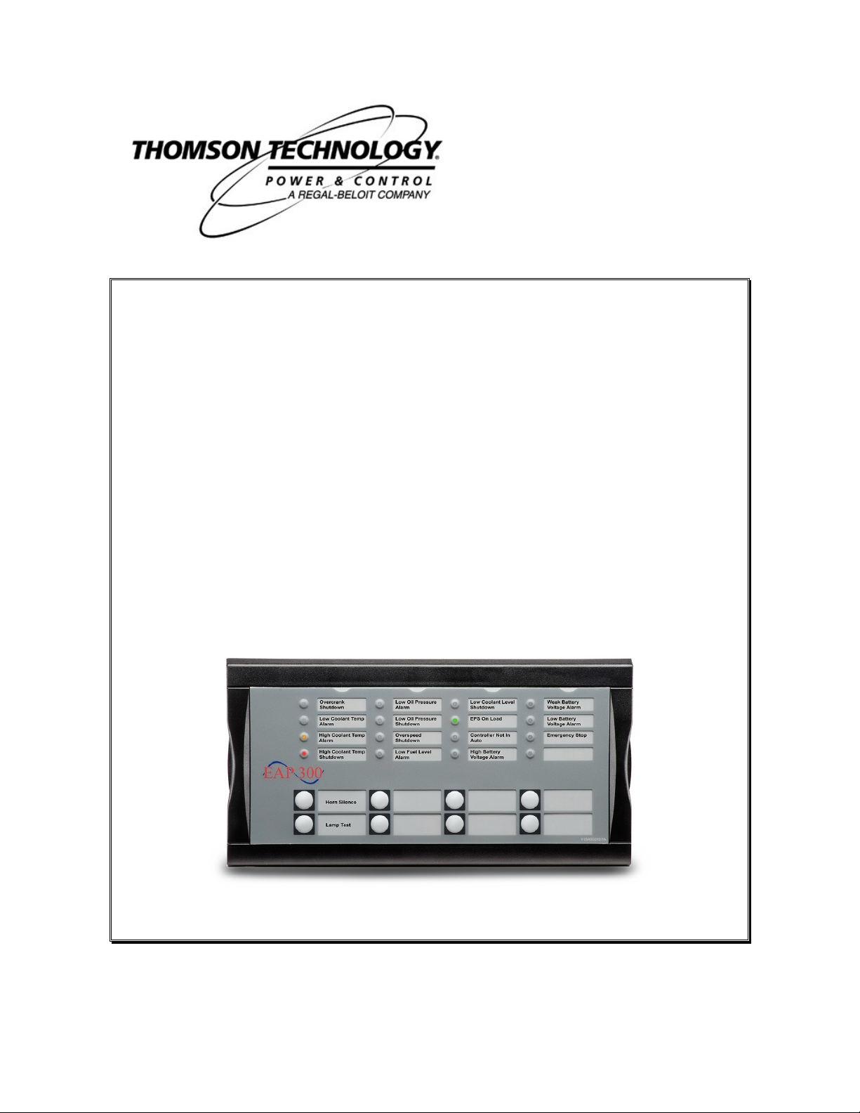
EAP 300
REMOTE ANNUNCIATOR
INSTALLATION MANUAL
r.0454A
9087A – 198th Street, Langley, BC Canada V1M 3B1 Telephone (604) 888-0110
Telefax (604) 888-3381 E-Mail: info@thomsontechnology.com www.thomsontechnology.com
PM084 Rev 0 08/06/20
Page 2

Page 3

EAP 300 REMOTE ANNUNCIATOR
CONTENTS
1. WARNINGS AND LEGAL INFORMATION ......................................................................................1
EGAL INFORMATION AND RESPONSIBILITY
L
LECTROSTATIC DISCHARGE AWARENESS
E
AFETY ISSUES
S
ACTORY SETTINGS
F
EFINITIONS
D
2. DESCRIPTION .......................................................................................................................................2
REAR VIEW .................................................................................................................................................2
3. INSTRUCTIONS.....................................................................................................................................3
FRONT VIEW ..............................................................................................................................................3
INSTALLATION: .........................................................................................................................................3
IRING
W
E
...........................................................................................................................................................4
RROR HANDLING
...............................................................................................................................................1
........................................................................................................................................1
...................................................................................................................................................1
..........................................................................................................................................5
....................................................................................................1
......................................................................................................1
PM084 REV 0 08/06/20 THOMSON TECHNOLOGY
Page 4

EAP 300 REMOTE ANNUNCIATOR
1
ous situation, which could result in
death, personal injury or damaged equipment, if certain guidelines are not
Be aware of the hazardous live currents and voltages. Do not touch any AC
led in accordance with the NEC (United States) or the CEC
1. WARNINGS AND LEGAL INFORMATION
Legal information and responsibility
Thomson Technology takes no responsibility for installation or operation of the engine set. If there is
any doubt about how to install or operate the engine controlled by the unit, the company responsible for
the installation or the operation of the set must be contacted.
The EAP 300 must be instal
Electrostatic discharge awareness
Sufficient care must be taken to protect the terminals against static discharges during the
installation. Once the unit is installed and connected, these precautions are no longer necessary.
Safety issues
Installing the unit implies work with dangerous currents and voltages. Therefore, the installation should
only be carried out by authorized personnel who understand the risks involved in working with live
electrical equipment.
measurement inputs as this could lead to injury or death.
(Canada) standards.
Factory settings
The unit is delivered with certain factory settings. Given the fact that these settings are based on
average values, they are not necessarily the correct settings for matching the individual engine.
Thus precautions must be taken to check the settings before running the engine.
Definitions
Throughout this document a number of notes and warnings will be presented. To ensure that these are
noticed, they will be highlighted in order to separate them from the general text.
Notes
NOTE:
The notes provide general information, which will be
helpful for the reader to bear in mind.
Warning
The warnings indicate a potentially danger
followed.
PM084 REV 0 08/06/20 THOMSON TECHNOLOGY
Page 5

EAP 300 REMOTE ANNUNCIATOR
2
2. DESCRIPTION
The annunciator panel (EAP 300) which can be connected to the MEC 310 via a CANbus
communication line. The EAP 300 has 16 configurable LEDs and 8 configurable buttons, which are
programmed with the TPS 300 PC utility software. It can be used as an interface to the MEC 310 for
indication of status and alarms together with buttons for e.g. remote alarm acknowledge and mode
selection.
Contents:
A DC/DC converter for the EAP 300 DC supply voltage and cable with an RJ12 plug in one end and
stripped wires in the other end is included in the EAP 300 Kit.
NOTE:
A maximum of 2 EAP 300 units can be connected
to each MEC 310.
NOTE:
The maximum length of the CANbus line is 200m.
REAR VIEW
Connectors:
CAN 1: DC supply (input) and CANbus communication to/from MEC 310 or other EAP 300
units.
CAN 2: CANbus communication to/from other MEC 310 or EAP 300 units and status relay
output.
End resistor: Dip switch for 120 Ω end resistor for the CANbus communication.
not used
Torque: 4 lb-in
EAP 300
Dip switch 2 is
PM084 REV 0 08/06/20 THOMSON TECHNOLOGY
Page 6

3
3. INSTRUCTIONS
FRONT VIEW:
EAP 300 REMOTE ANNUNCIATOR
The configurable LEDs are named 1 to 16. Buttons are named 1 to 8.
INSTALLATION:
Mount on a flat surface of a Type 1 Enclosure. Note the maximum ambient temperature rating is
60 oC
Panel Cut-out Detail:
PM084 REV 0 08/06/20 THOMSON TECHNOLOGY
Dimensions in millimetres ( 1 inch = 25.4 mm )
Page 7

EAP 300 REMOTE ANNUNCIATOR
4
n
w
+5
n
w
n
Wiring
MEC 310
EAP 300
CAN L CAN H
59 57
R=120 Ω
End resistor
OFF
ON
1 2
CAN 1 CAN 2
Gr
Ye
Bl
ee
llo
ue
Gr
Ye
W
Bl
ee
llo
hit
ac
W
Bl
Bl
ue
Re
hit
ac
d
Co
N
VD
C
0
VD
C
Comm. to
other units
Cable shield
N
m
mo
Status relay
End resistor:
The 120 Ω end resistor on the MEC 310 is needed at all times. The default setting of the end
resistor on the EAP 300 panel is ON. Thus, the dip switch is at the right position if only one EAP 300
is connected. If there are two EAP 300’s connected, the end resistor of the EAP 300 with a
connector plug in both CAN 1 and CAN 2 must be switched off.
1 unit connected:
2 units connected:
Dip switch no. 1 on the unit should be set to ON.
Dip switch no. 1 on EAP 300 no. 1 should be set to OFF and dip
switch no. 1 on EAP 300 no. 2 should be set to ON.
WIRE TYPE NOTES:
Wire Size 30-12 AWG copper conductors (60-70 oC)
The cable between the terminal blocks should be shielded twisted pair (Belden 9841 or equivalent)
The maximum length of CANbus line is 200m.
PM084 REV 0 08/06/20 THOMSON TECHNOLOGY
Page 8

EAP 300 REMOTE ANNUNCIATOR
5
CAN ID configuration
The CAN ID for the EAP 300 can be changed by the following procedure:
1. Push-button no. 7 and no. 8 at the same time to activate the CAN ID change menu, this will
activate the LED for the present CAN ID number, and LED no. 16 will be flashing.
2. Use button no. 7 (increase) and button no. 8 (decrease) to change the CAN ID according to
the table below.
3. Press button no. 6 to save the CAN ID and return to normal operation.
Selection of CAN ID:
CAN ID Indication of CAN ID selection
0 CANbus OFF: LED 16 flashes
1 LED 1 light steady + LED 16 flashes (default value)
2 LED 2 light steady + LED 16 flashes
Status relay
The status relay will activate approximately 5 sec. after power up.
Programming
The programming of the EAP 300 is accomplished through the TPS 300 programming software.
Error handling
Duplicate CAN ID
If two units on the CANbus have the same CAN ID, LED no. 1 to 4 will flash quickly. In this case
press button no. 6 to jump into the CAN ID change menu and select another CAN ID for the unit.
NOTE: The EAP 300 can be used with the supported CANbus Expansion I/O modules.
PM084 REV 0 08/06/20 THOMSON TECHNOLOGY
 Loading...